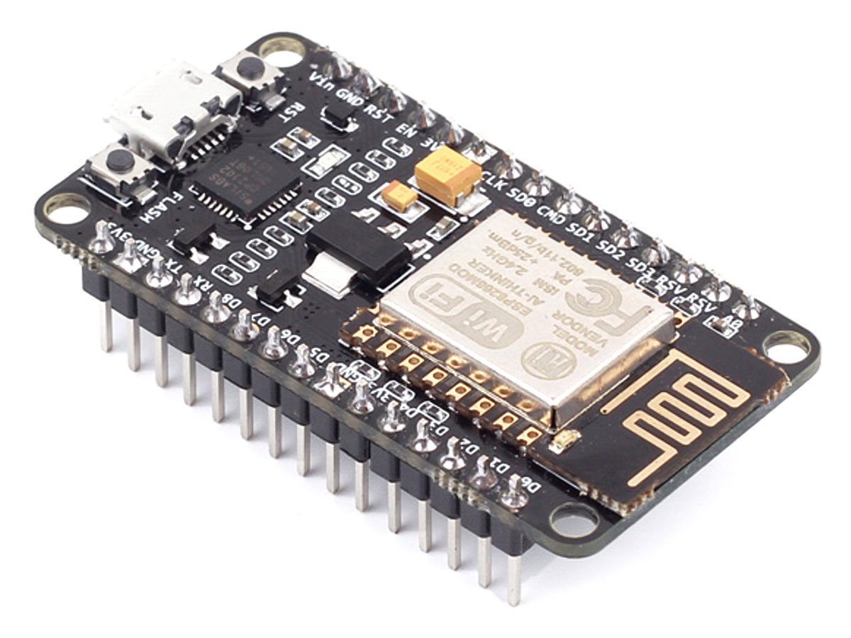
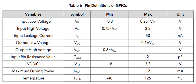
For this project I´m using a NodeMCU development boardwith an integrated ESP8266 chip that comes with integrated WIFi and Bluethoot module antena. From the datasheet, I will highlight some things that I find usefull to me (or that I understand).
• Integrated TCP/IP protocol stack
• Supports antenna diversity
• WiFi 2.4 GHz, support WPA/WPA2
• Support STA/AP/STA+AP operation modes
• Support Smart Link Function for both Android and iOS devices
• Operating temperature range -40C ~ 125C
• Dual and single antenna Bluetooth co-existence support with optional simultaneous receive (WiFi/Bluetooth) capability.
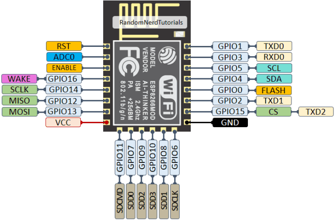
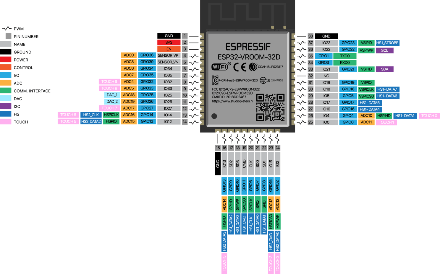
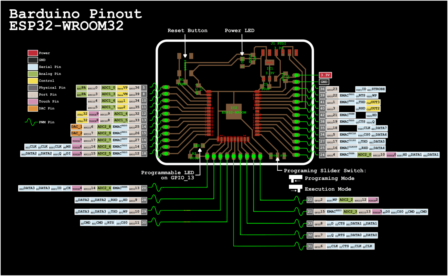
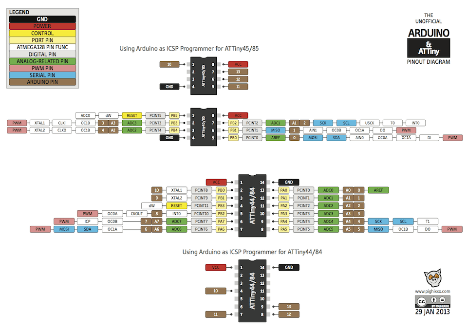
ESP8266 Pinset
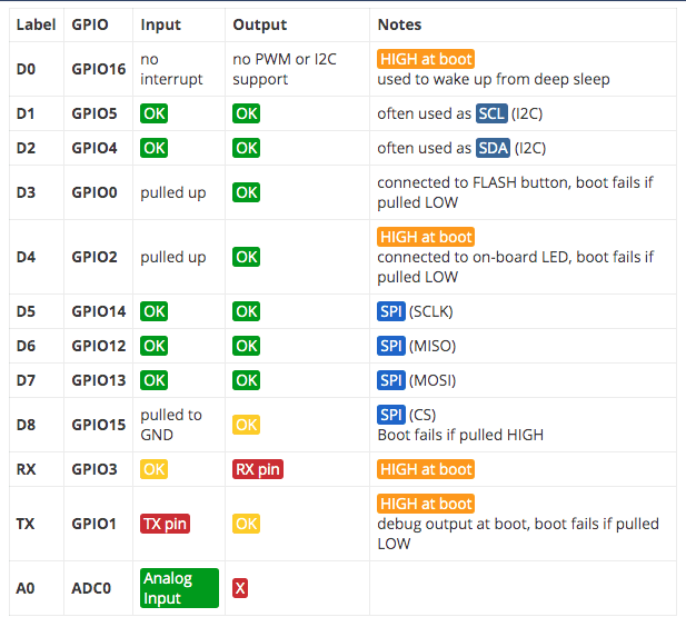
BEST PINS TO USE

The ESP12-E NodeMCU Kit is one of the most used ESP8266 development boards. It features 4MB of flash memory, access to 11 GPIO pins, and one analog-to-digital converter (ADC) pin with 10 bit resolution. The board has a built-in voltage regulator and you can power up the module using the mini USB socket or the Vin pin.
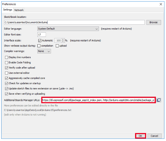
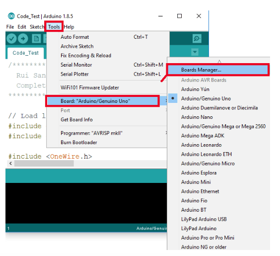
Uploading code to the board is as easy as uploading code to the Arduino, there’s no need for an FTDI programmer, as it comes with a usb-to-serial converter built-in.
This is the board we use more often in our Wi-Fi and IoT projects. It is very versatile and it’s great for beginners. So, if this is your first time with the ESP8266, this module is a great choice. Take a look at the links below to find out the ESP8266 12-E NodeMCU kit on your favorite store.
not all GPIOs are accessible in all development boards, but each specific GPIO works in the same way regardless of the development board you’re using. If you’re just getting started with the ESP32, we recommend reading our blog: Getting Started with the ESP32 Development Board.
At the moment, there are a wide variety of development boards with the ESP8266 chip that differ in the number of accessible GPIO’s, size, form factor, etc… There are several Development boards Like a 36 pin development board and a ESP32-Pico-Kit and several others. I don’t treat them all here, but you van use the pin definitions here as reference.


In that platformio.ini you have to declare the enviroment, the platform, the board and the framework like this:
[env:nodemcuv2]
platform = espressif8266
board = nodemcuv2
framework = arduino
The software does it automaticaly when you create a new project and define this settings, but if you are going to add some addition external libraries you will also have to declare them here, I´ll explain a bout this in the Breathe example.

Another important thing is that if you want to code it with the same arduino language, you have to call the Arduino library in the beggining of the code:
#include <Arduino.h>
If you don´t call the library, it won´t recognize a lot of things in your code like Delay, Output, PinMode, etc.
D8 (16 - GPIO15)
D6 (6 - GPIO12)
Another thing that was interesting to me was to be able to Flash the NodeMCU with Micropython with a RasperryPI3 thourgh terminal, but I think I´ll document that in networks.
pip install esptool
esptool.py --port /dev/ttyUSB0 erase_flash
esptool.py --port /dev/ttyUSB0 --baud 460800 write_flash -- flash_size=detect 0 esp8266-20170108-v1.8.7.bin (this correspondes to the version you donwloaded)

web page was built with Mobirise site templates