Laser Cutting:
What is Laser Cutting and how it works.
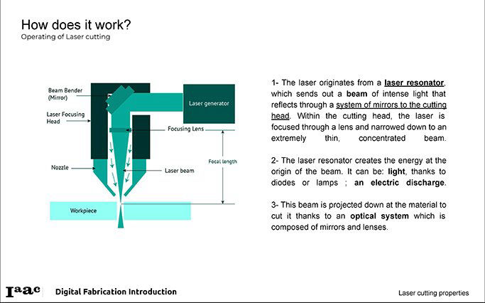
What is Laser Cutting and how it works.
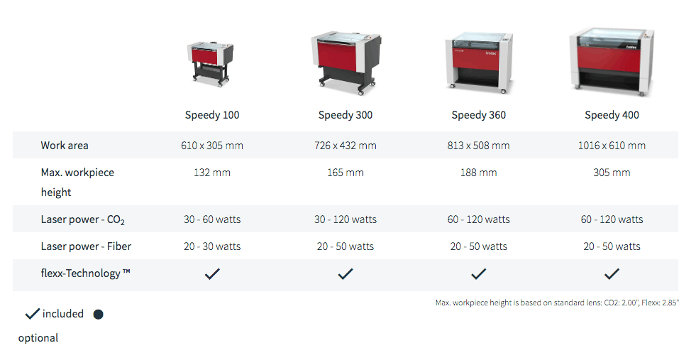
Different types of Laser Cutting Machines and some of their specifications.
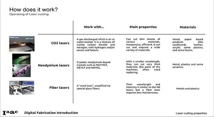
- CO2
- Neodymium (Nd-YAG):
- Fiber
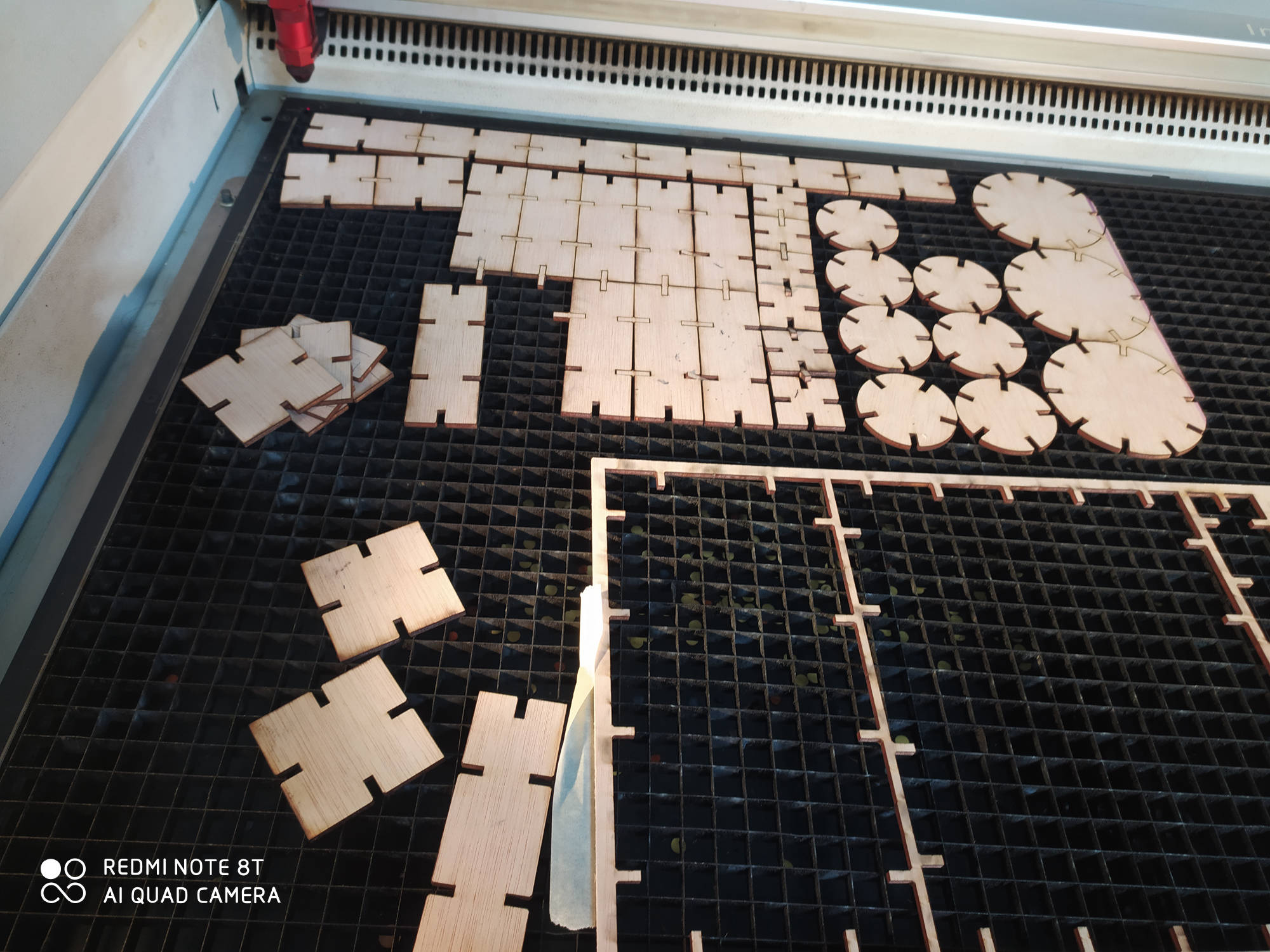
Description of the Laser Cutting process.
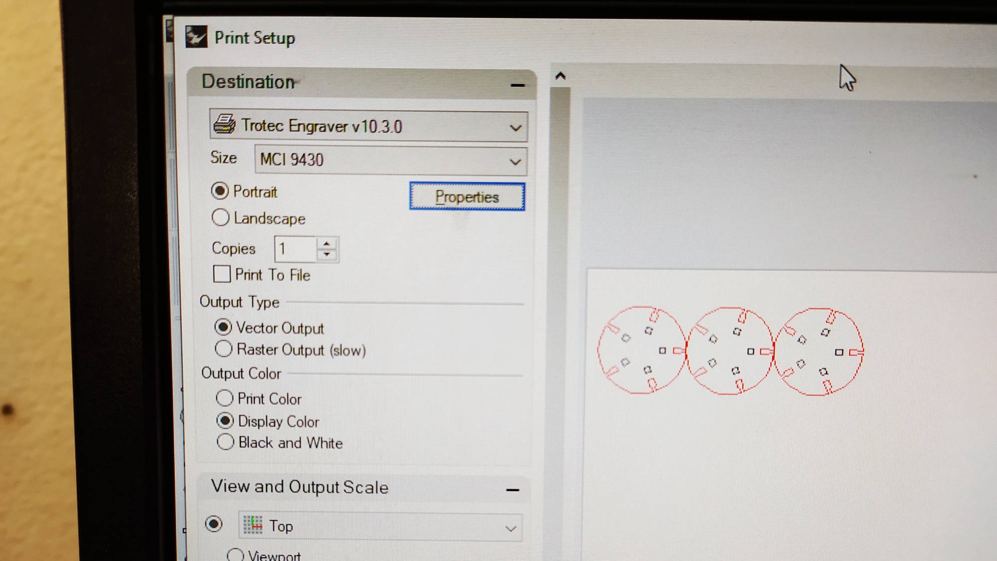
- Machine / Lab Settings.
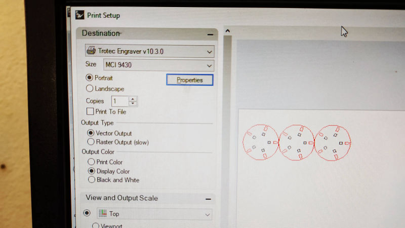
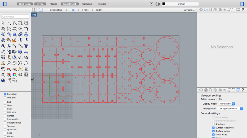
- Rhino File Settings.
- Trotec Job Control Settings.
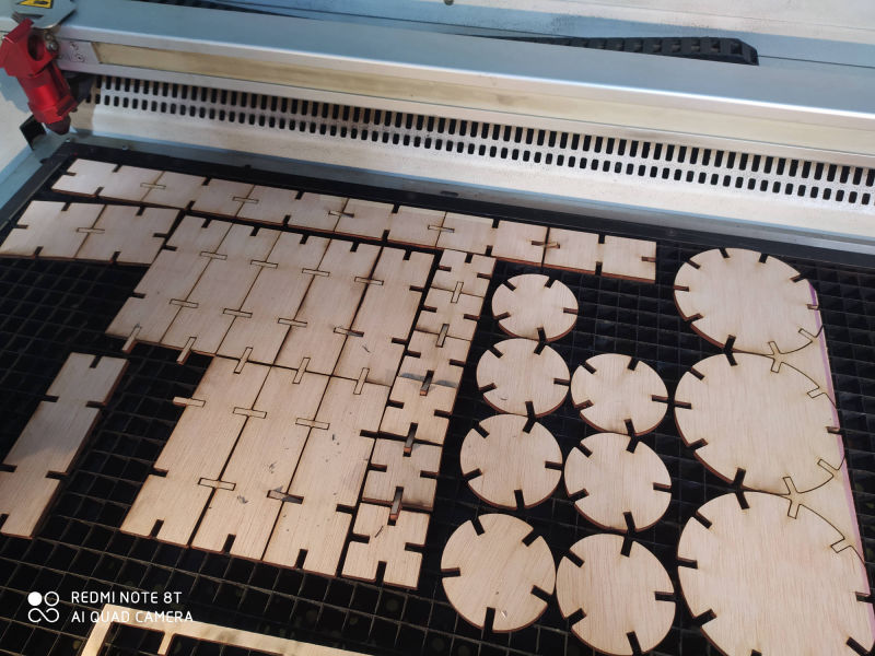
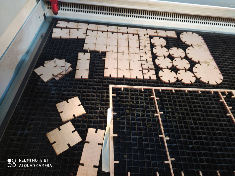
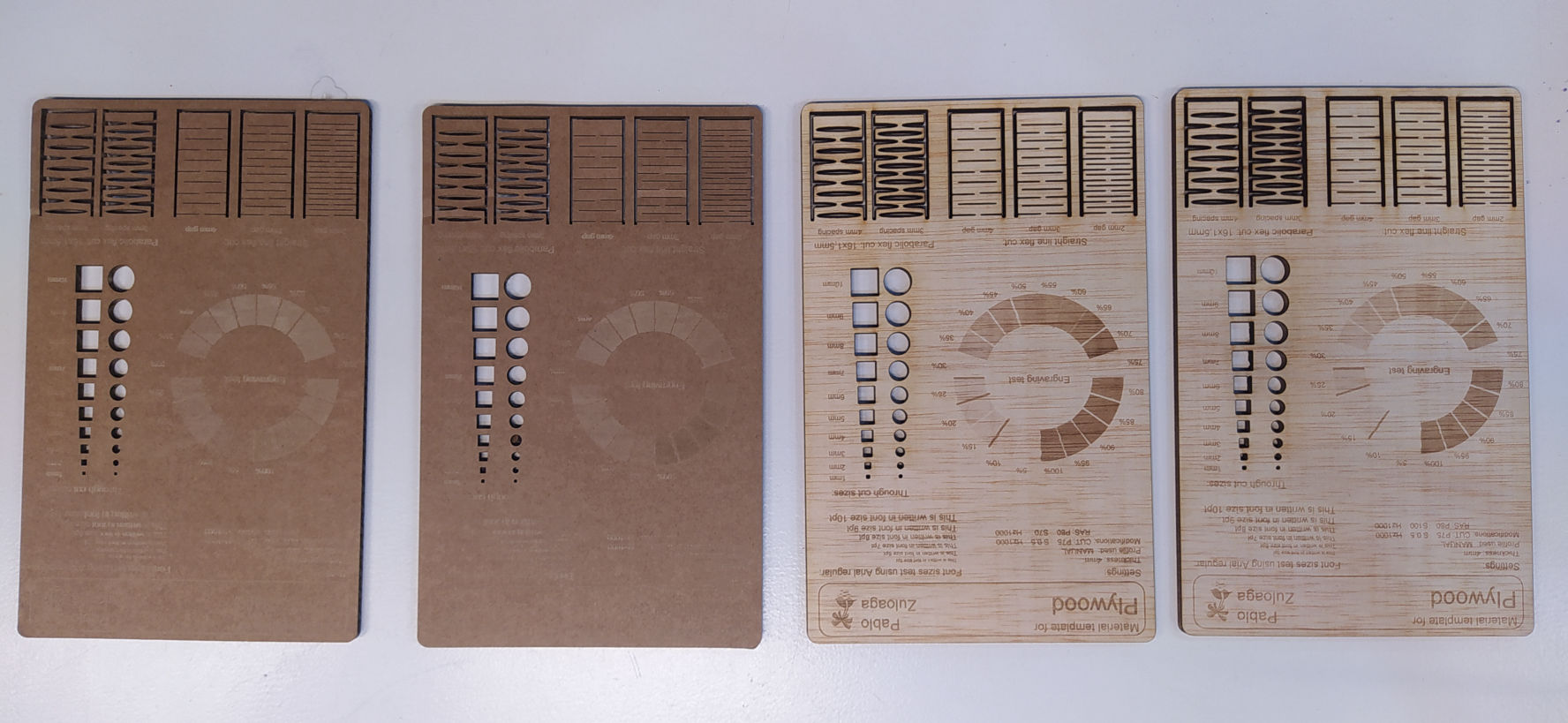
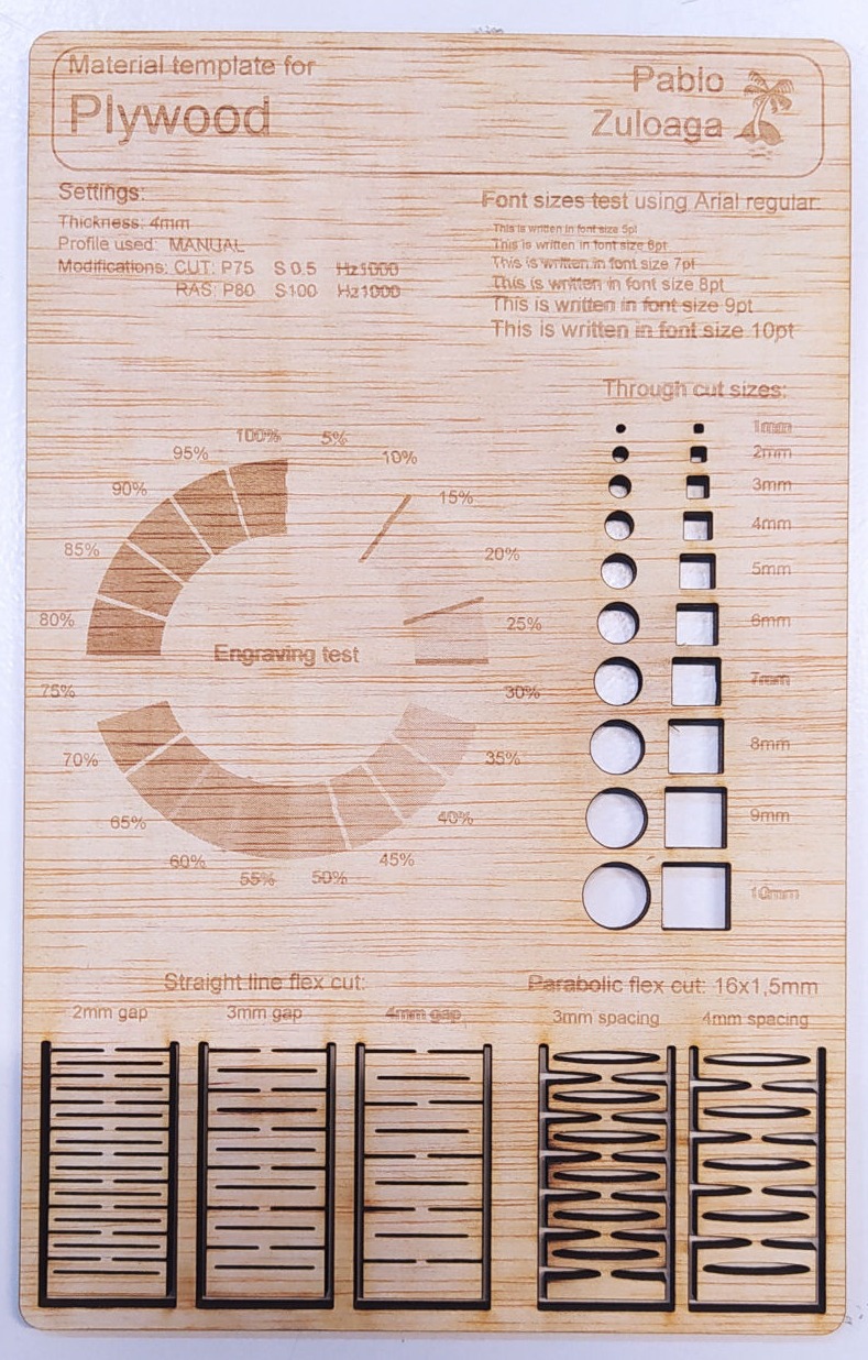
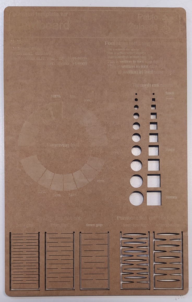
Here is the explanation of how to calibrate the laser cutter and some test I did.
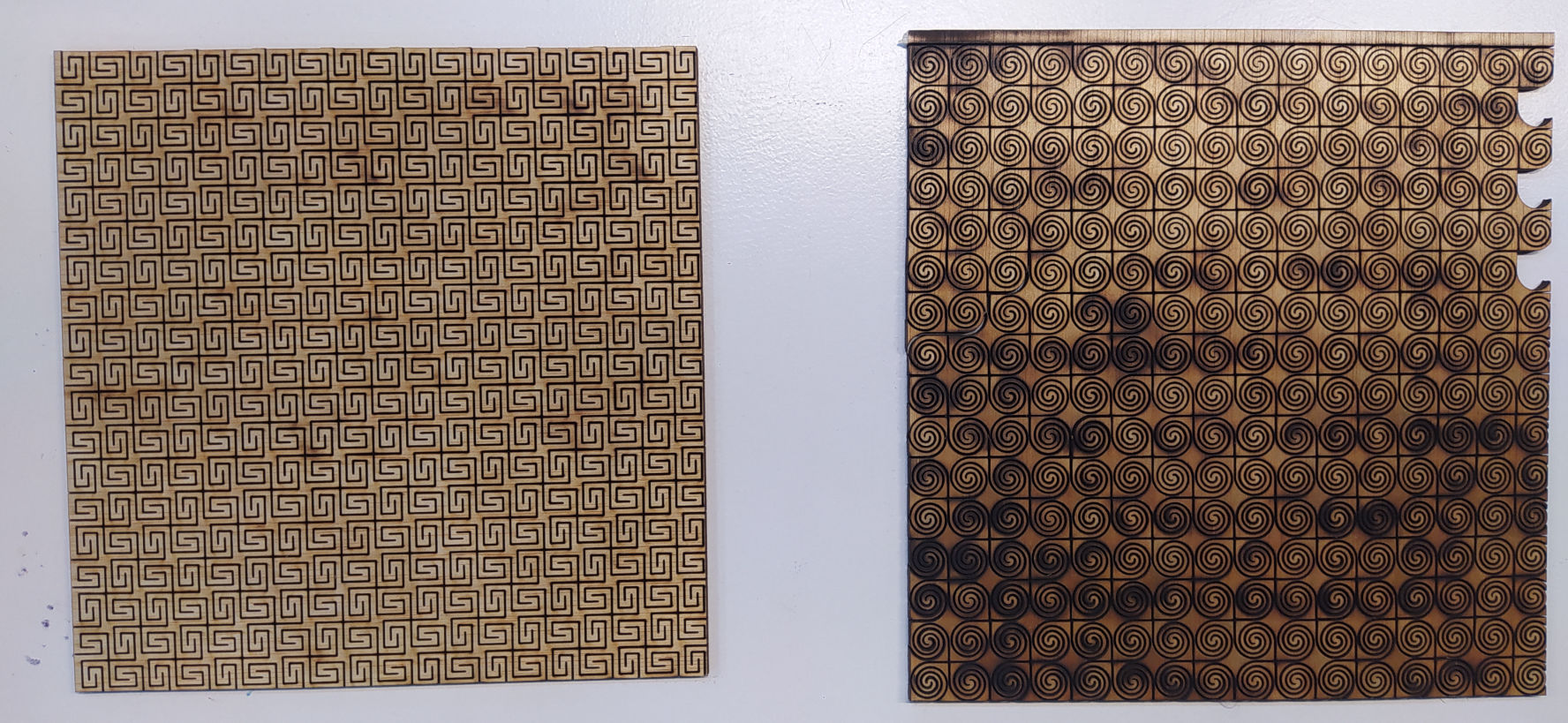
- Laser Testing.
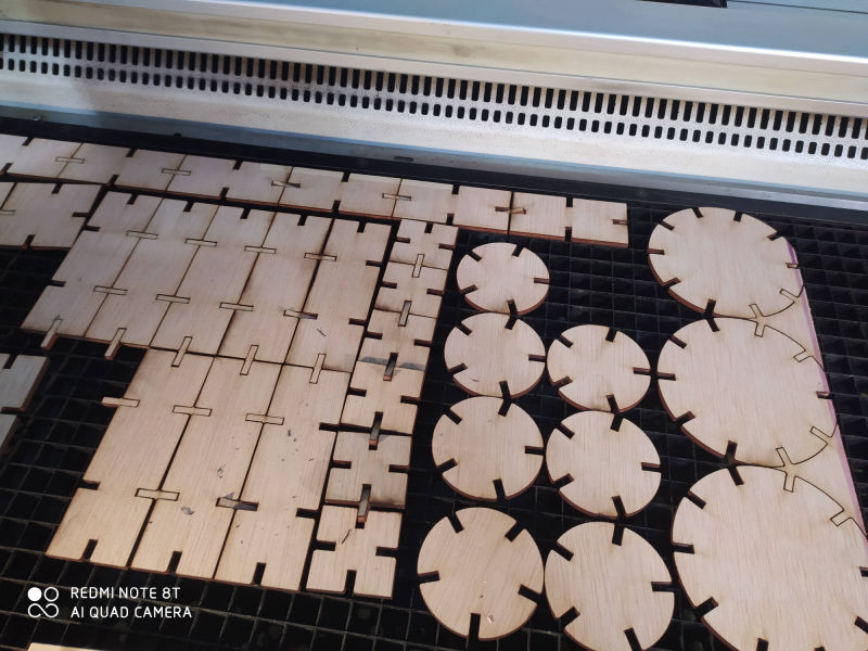
- Flexible Kerf Testing.
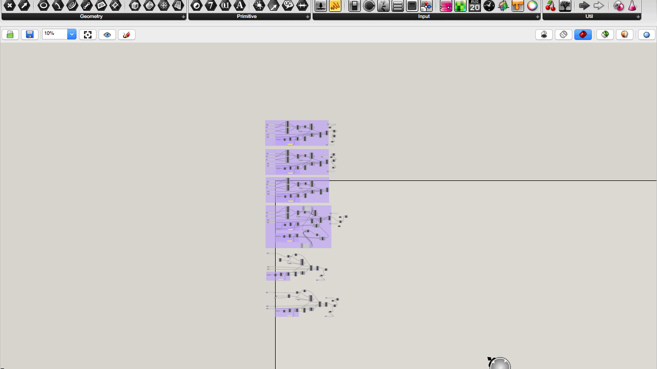
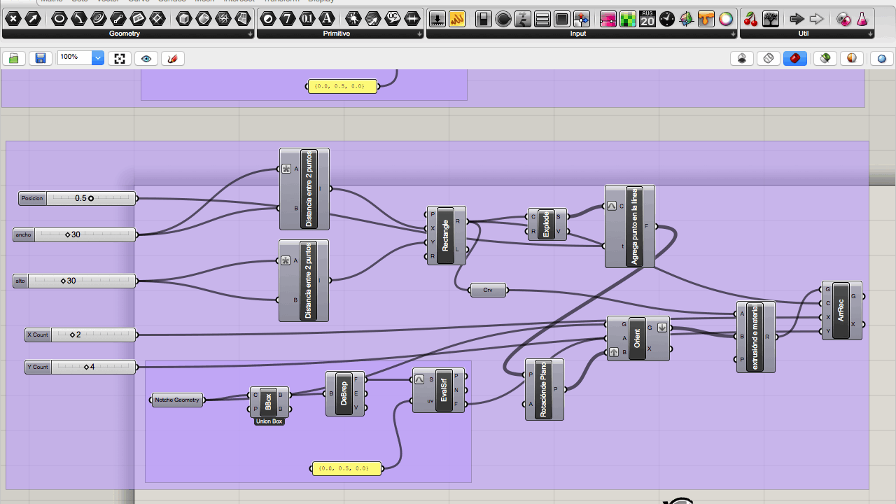
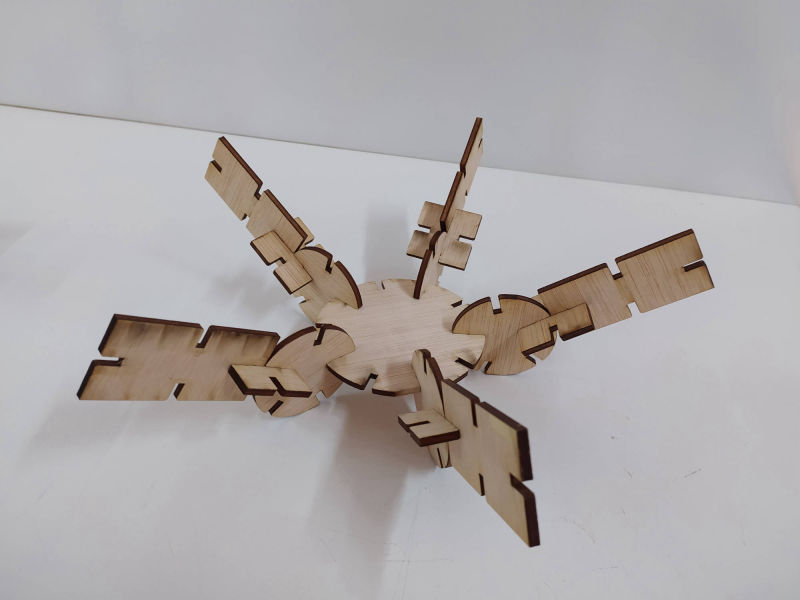
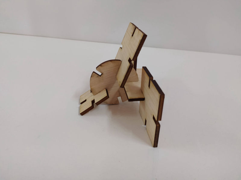
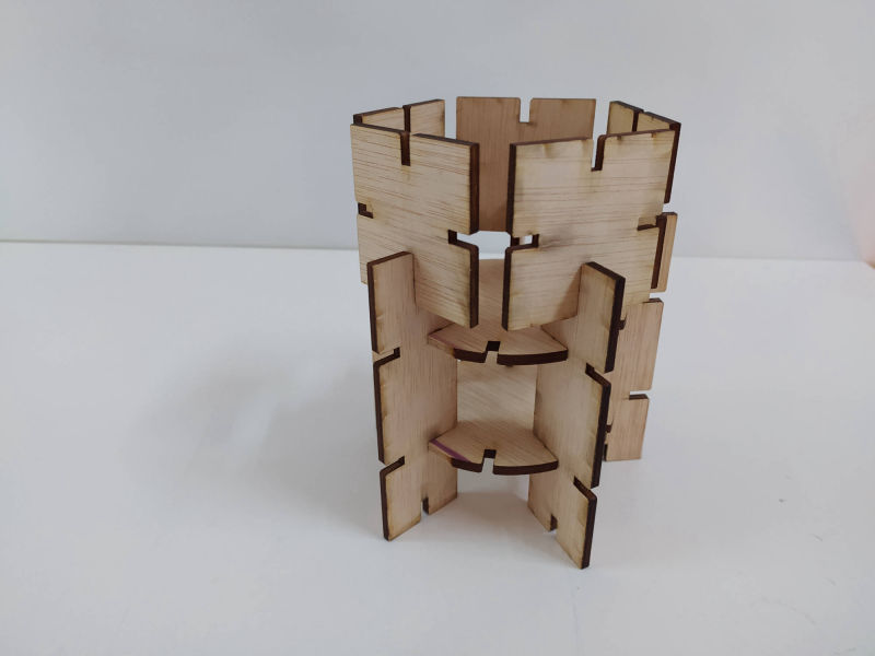
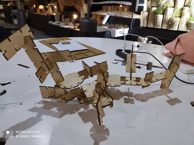
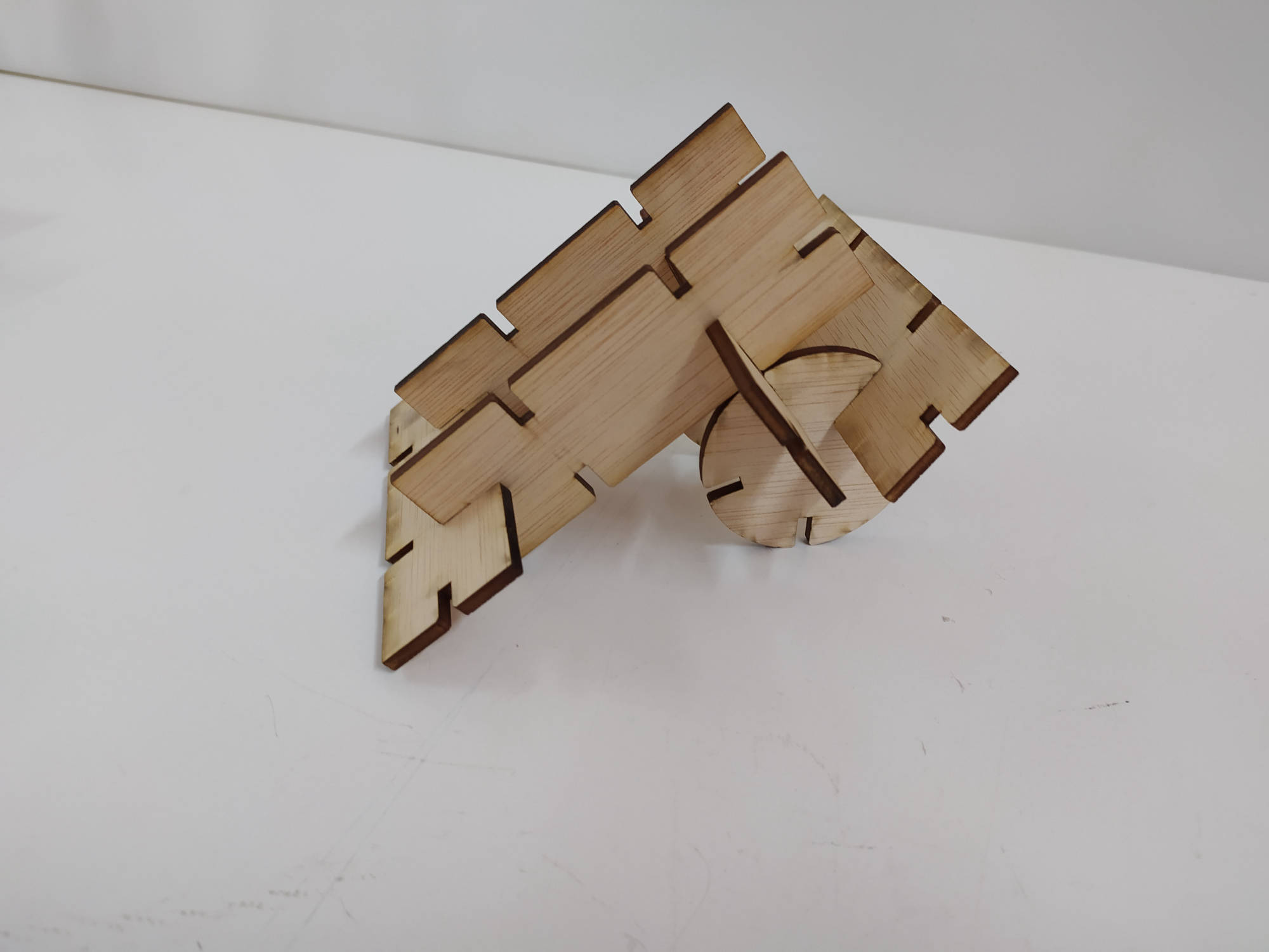
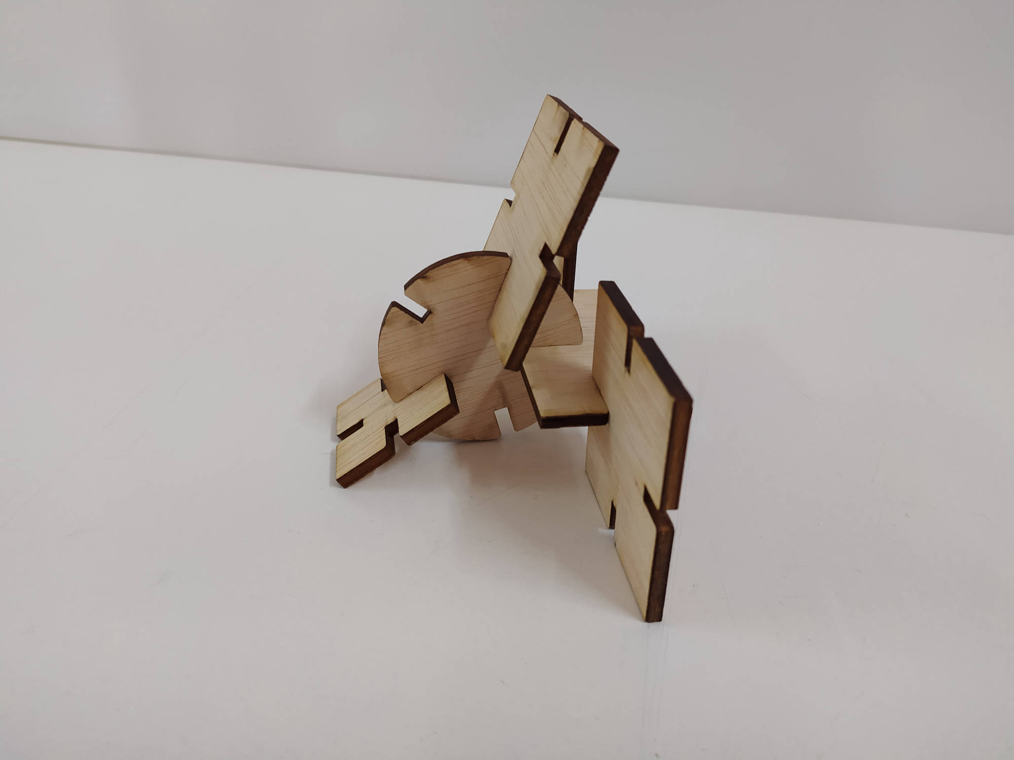
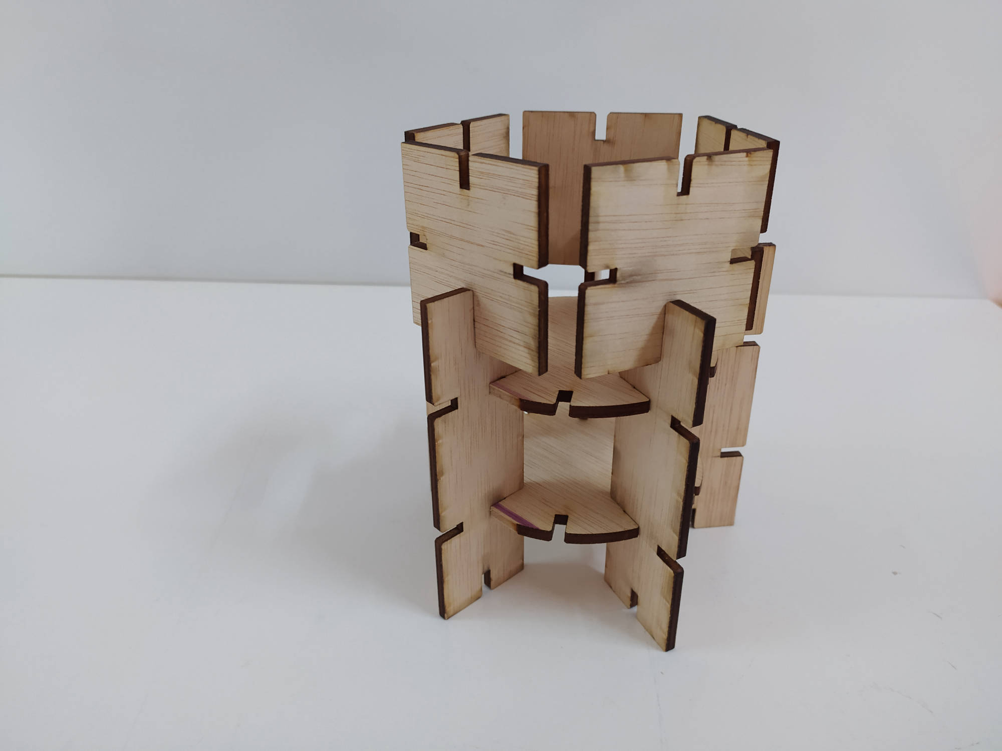
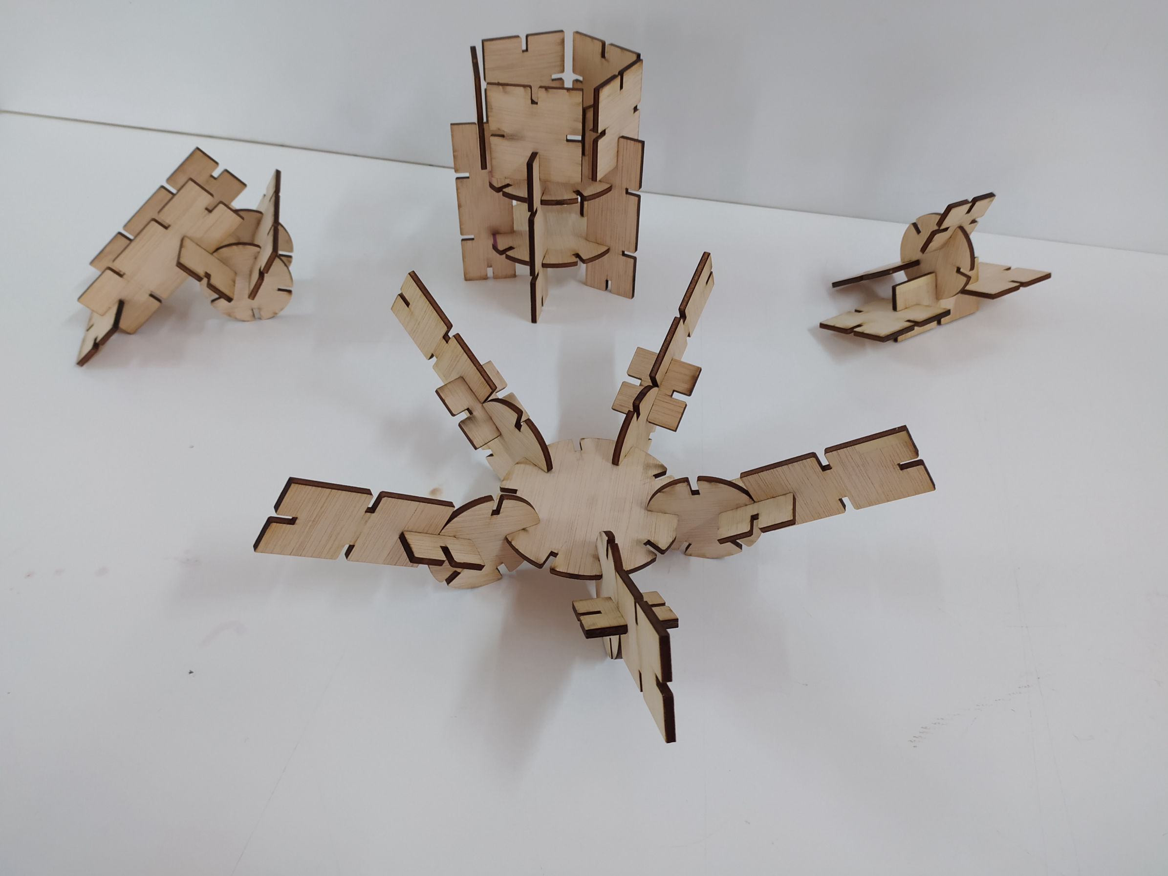
A brief description of the parametric design process.
The explanation of the process:
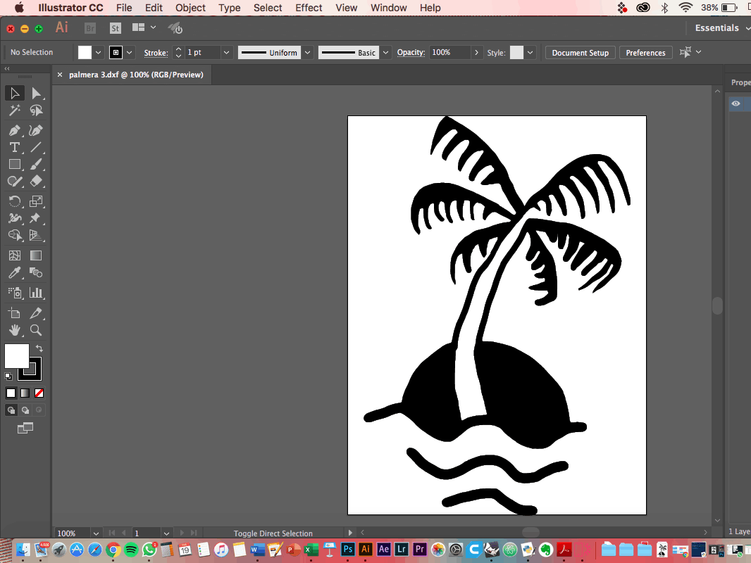
- Silhouette Cameo Setting
- Illustrator Design
Final reflections and considerations about this week.
Laser cutting is a technology that uses a high-power laser, that is directed through mirrors to end up in an optic lens that focuses it and generates a laser beam to cut materials. It moves in Y and X axis, and has also the possibility to move the bed Z axis to help you focus it on the material. It is Computer Numerical Controlled through a G-Code of the pattern to be cut, melt, vaporize away, raster or engraved onto the material, leaving an edge with a high-quality surface finish. Industrial laser cutters are used to cut flat-sheet material as well as structural and piping materials. I could say that laser cutting machines works similar to when you play with the sun and a magnifying lens to burn a piece of paper... in a simplified way.
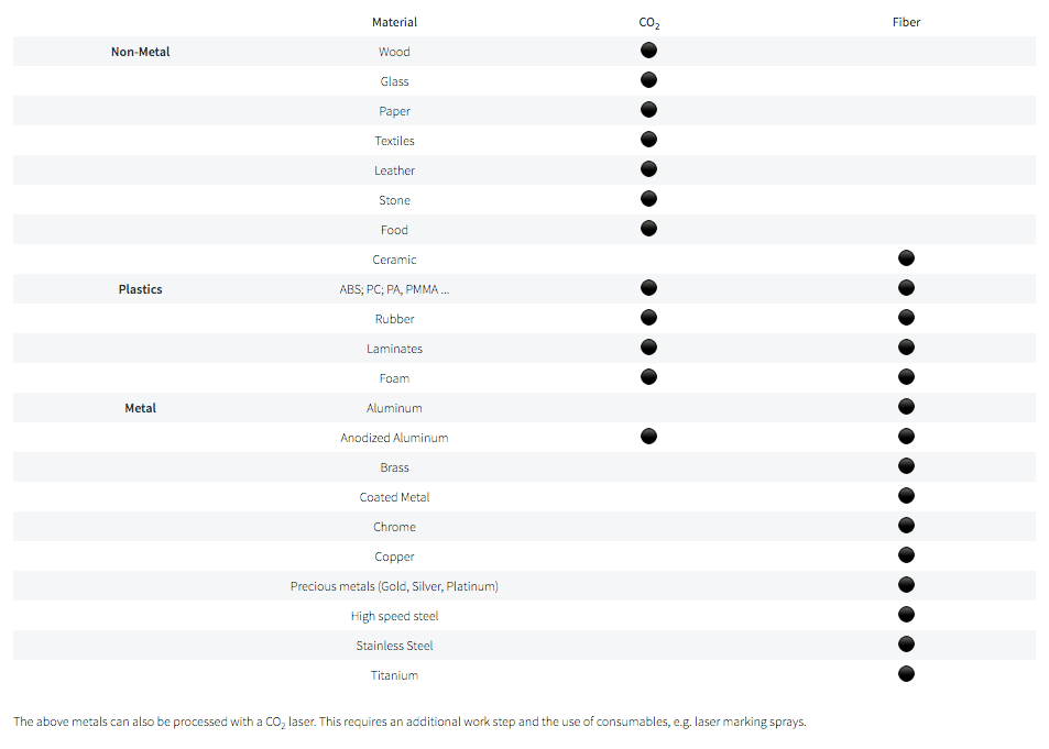
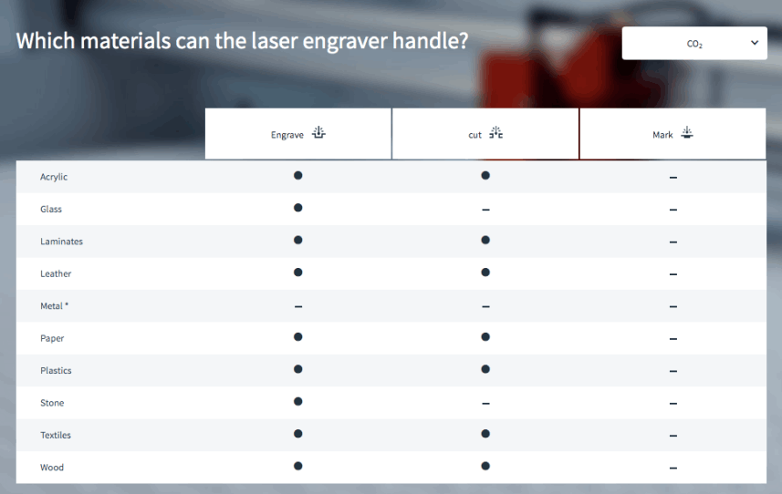
Co2
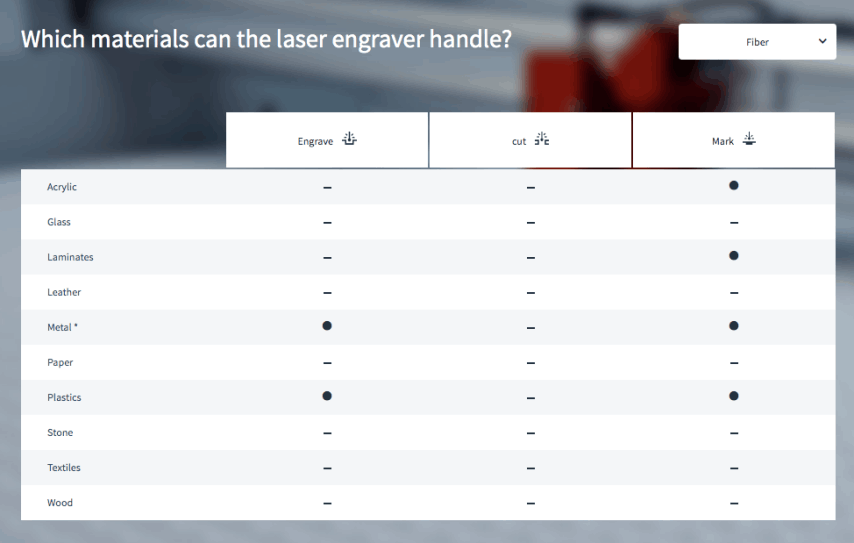
Fiber
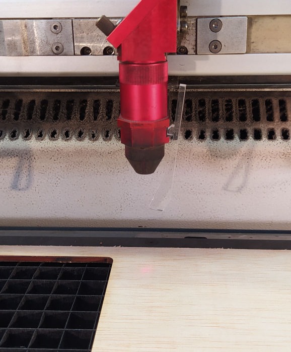
LASER CALIBRATION:
To calibrate the focus of the laser, you need to use a tool that usually comes with the laser (or could be fabricated in acrylic like the one in FabLab Barcelona).
You hang the tool from one side of the laser as it is shown in the picture, and then you start to slowly raise the bed until it softly touches the tool and makes it fall. That will guarantee that your laser is focused.
Other focus problems might come from a dirty lens, and in that case there are special cloths for cleaning it carefully.

Mobirise web maker - Click now