Intro:
Description and reflections of this weeks learnings.
Description and reflections of this weeks learnings.
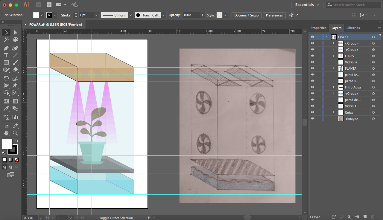
Here is an explanation of some basic concepts of Illustrator an vectorial image software.
Some basic explanation of how I used illustrator.
Description of the web tool I used for creating my website and how to connect it to my Git.
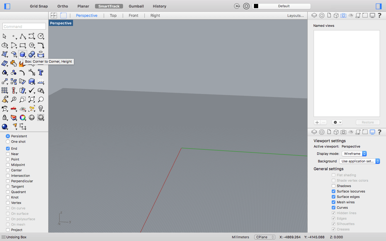
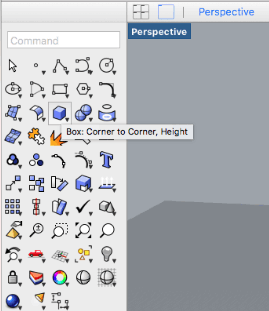
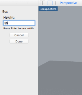
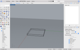
These are some basic concepts I learned of Rhino and used in the design of the first version of my project.
Some final comments and learnings about this process.
3D stands for three dimensions, which means that the object you create will not only have height and width, but also will have depth, which is how our eyes see objects in real life because of the perception our eyes give to our brain when seeing something with two different points of view and mixing them.
When designing in 3D, each software has its own proprietary file format, and each industry has some favorite ones because of certain characteristics, but there are some neutral formats that are common between most 3D softwares and can hold different information like shapes o geometry, the materials or the appearance of the shape, lightning and other scene characteristics, and animations. I'm going to explain a bit about some of them, or at least the ones I used most during my FabAcademy, using an explanation I found in this article of All3DP.
STL:
STL (STereoLithography) is one of the most important neutral 3D file formats in the domain of 3D printing, rapid prototyping, and computer aided manufacturing. It generates a mesh which represents the geometry or shape of the object, but without any other characteristics like colors, appearance, lightning or animations. STL encodes the surface geometry of a 3D model approximately using a triangular mesh and it ignores appearance, scene, and animations. It is one of the simplest and leanest 3D file formats available today.
OBJ:
Is a format that includes the geometry mesh of the object but it can also store appearance related information, so it can be used in multi color 3D printing and others. The OBJ file format supports both approximate and precise encoding of surface geometry. When using the approximate encoding, it doesn’t restrict the surface mesh to triangular facets. If the user wants, he can use polygons like quadrilaterals. When using precise encoding, it uses smooth curves and surfaces such as NURBS. The OBJ format can encode color and texture information. This information is stored in a separate file with the extension .MTL (Material Template Library). It does not support any kind of animation. The format specifies both ASCII and binary encodings, but only the ASCII encoding is open source.
FBX:
COLLADA:
Collada is a neutral file format used heavily in the video game and film industry, and supports geometry, appearance related properties like color, material, textures, and animation. In addition, it is one of the rare formats supporting kinematics and physics. The COLLADA format stores data using the XML markup language.
3DS:
3DS is a proprietary file format used in architecture, engineering, education, and manufacturing. It retains only the most basic information about geometry, appearance, scene, and animation, and uses a triangular mesh to encode the surface geometry approximately, the total number of triangles being limited to 65536. It stores appearance related properties like color, texture, material, transmissivity etc. Scene information such camera position, lights can also be stored, but the format does not support directional light sources.
IGES:
IGES (pronounced eye-jess) is a neutral old timer used primarily in the defense industry and in the field of engineering. It was developed in the mid-seventies by the US Air Force. The IGES format is an ASCII encoding that is extremely flexible when it comes to representing surface geometry. It has the ability to use circuit diagrams, wireframes, precise free-form surfaces or CSG for storing geometry related information. The format can also store colors but does not support material properties like textures, material type etc. Animation is also not supported.
STEP:
STEP (The Standard for the Exchange for Product Data) or ISO 10303 was developed as a successor of the IGES file format. It is widely used in engineering related fields like automotive and aeronautic engineering, building construction etc. The corresponding file format is *.STP. The STEP format supports all the features supported by the IGES format. In addition, it can also encode topology, geometrical tolerances, material properties like textures, material types, and other complex product data.

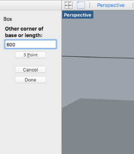

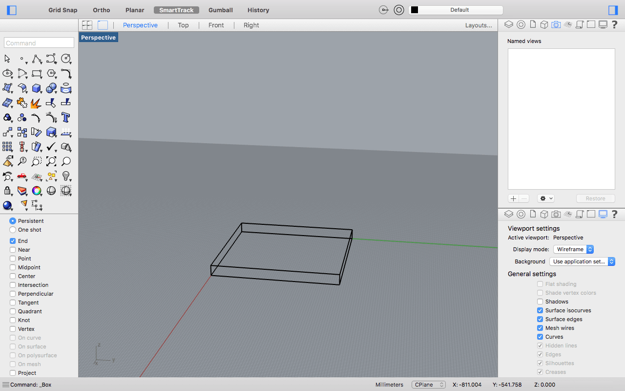
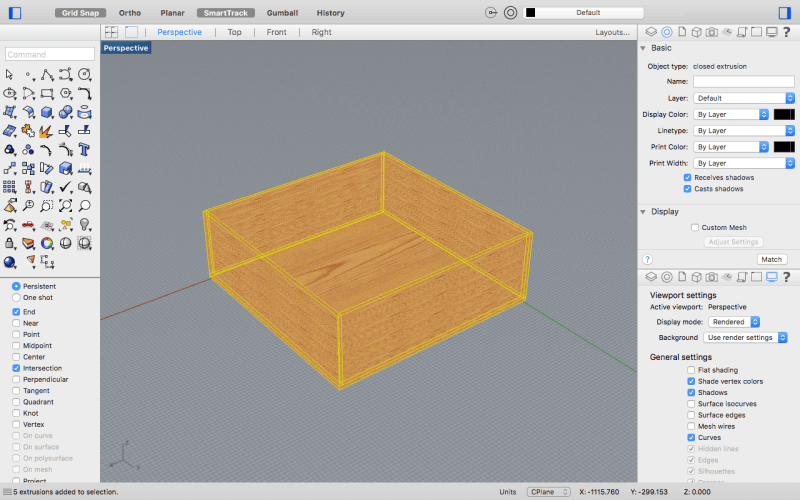
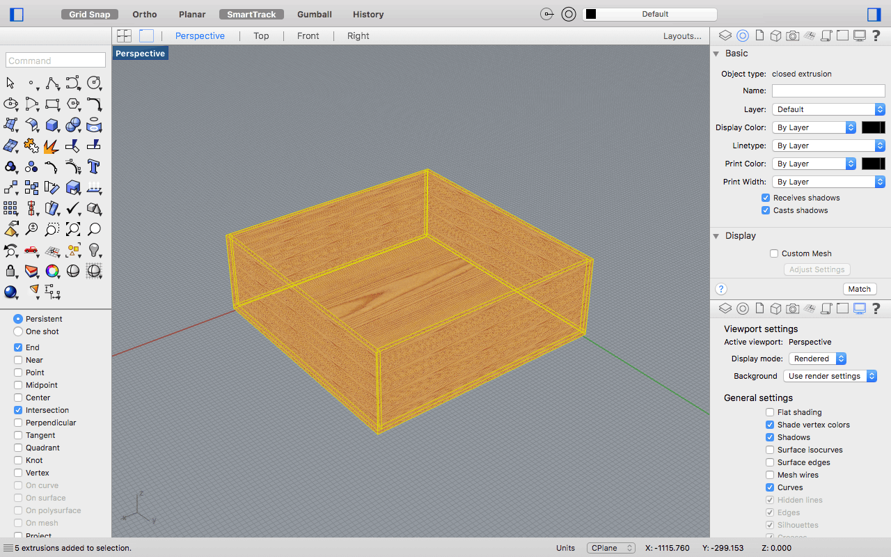
- 1 Base (600mm x 600mm).
- 2 Lateral (600mm x 1200mm).
- 2 front and rear (590mm x 1200mm).
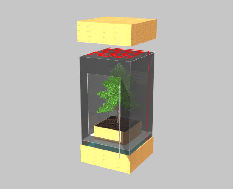
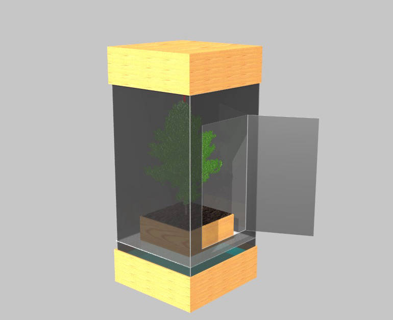
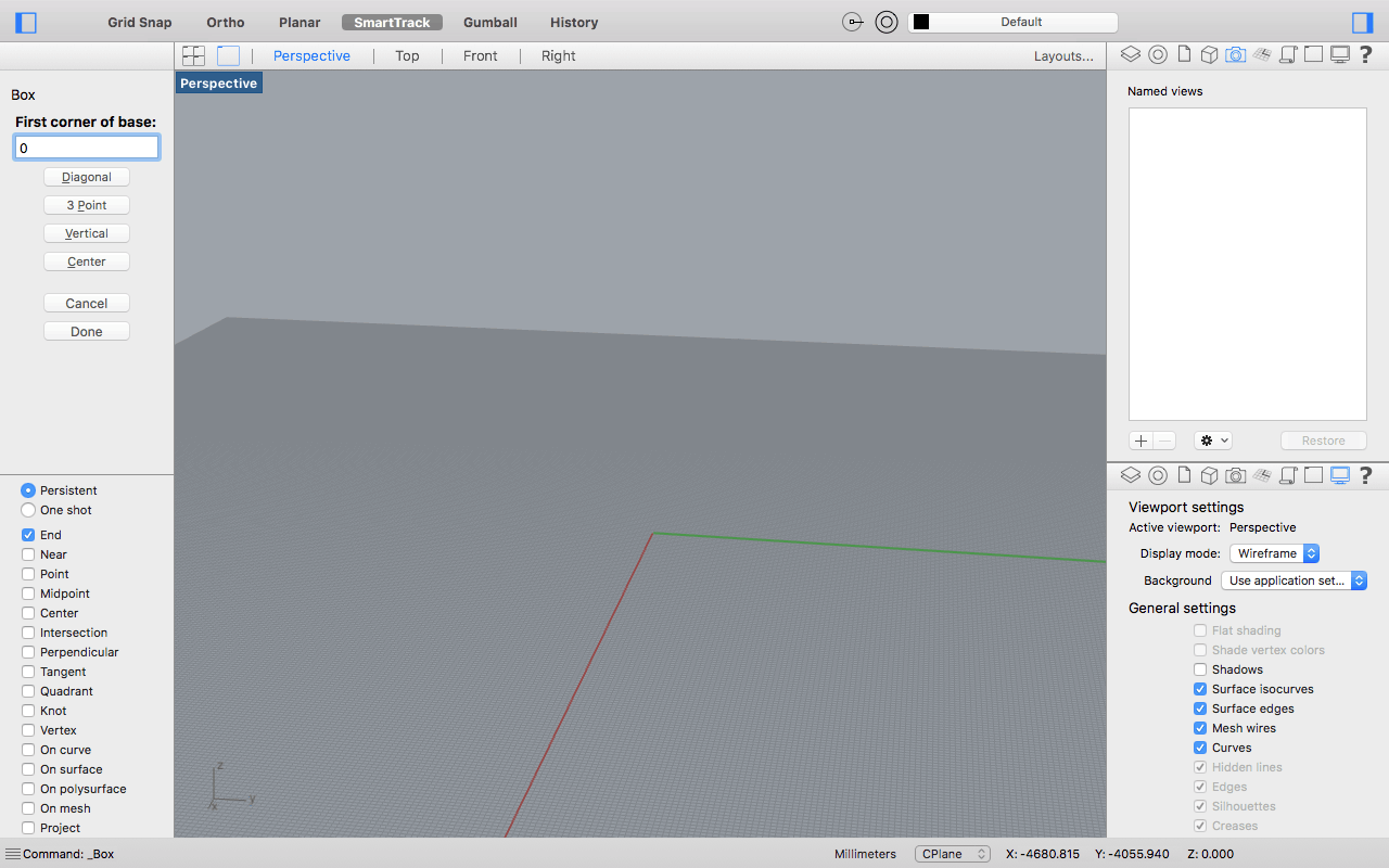
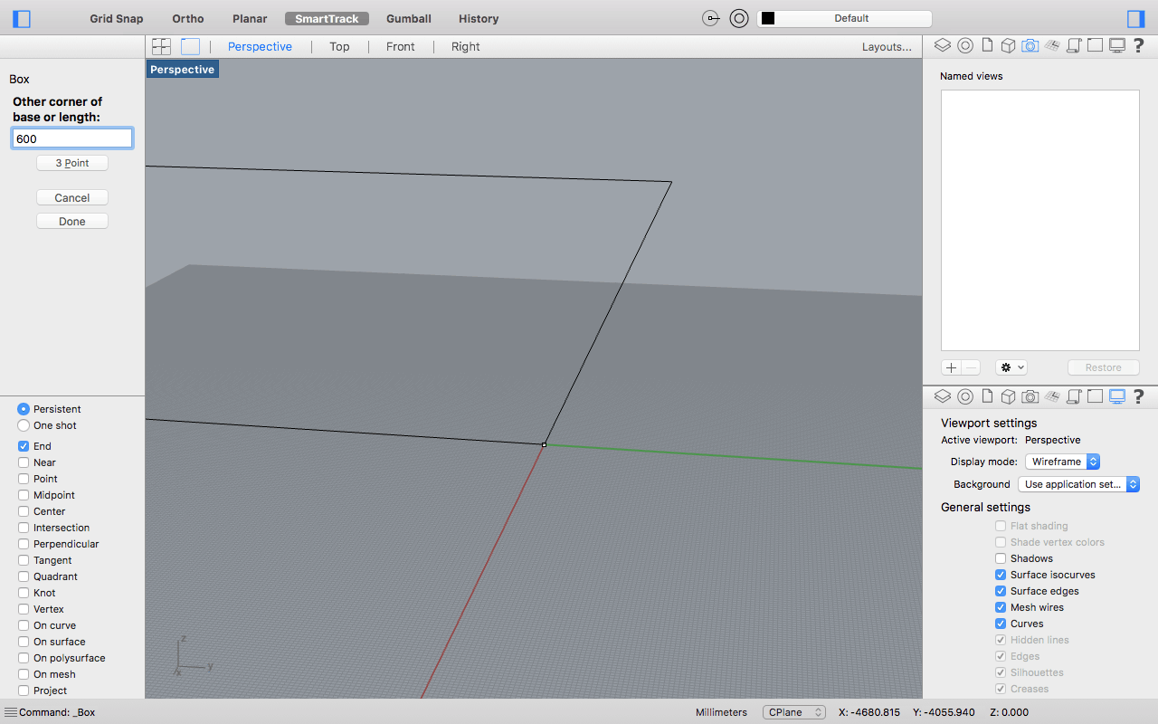
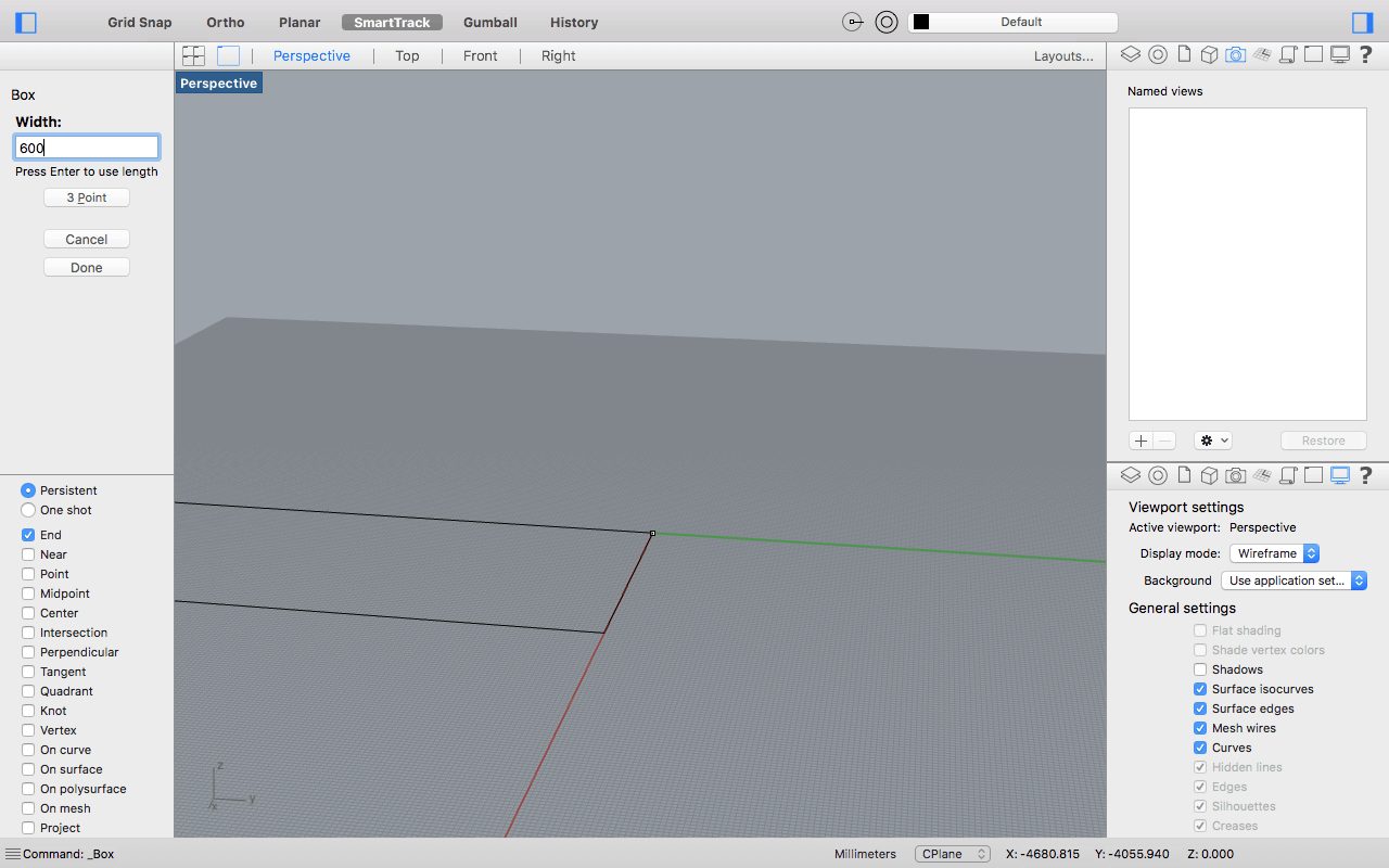
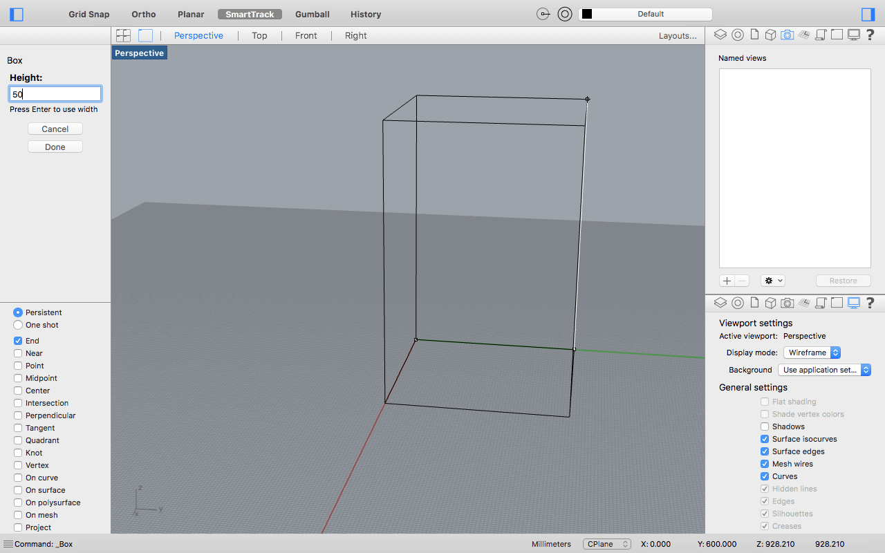
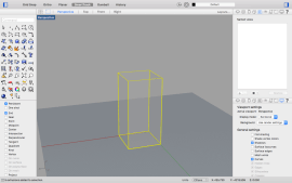
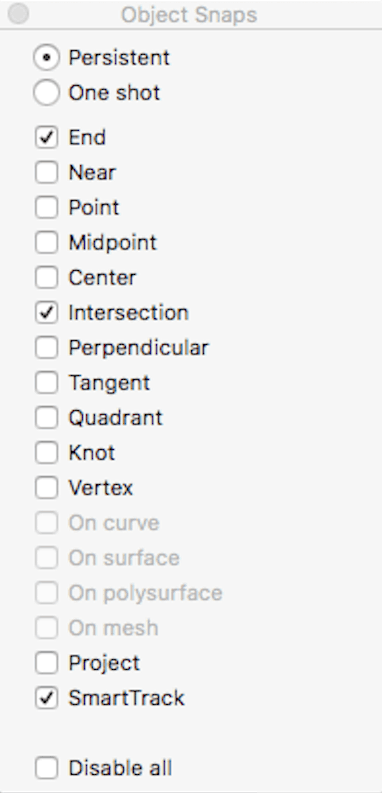
I repeated this process for each of the parts starting in point 0 and then with the OBJECT SNAPS TOOL and adjusted it to SNAP at the END and INTERSECTION of the pieces, and thus joined each corner with the corresponding corner of the other piece that should be connected.
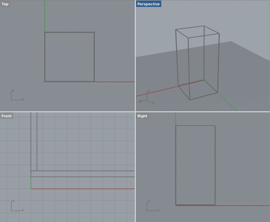
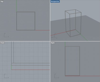
* Using the top and front view, is a good way to see if everything is alligned, so it is important to be changing between views to check that everything is placed correct.
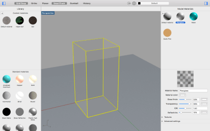
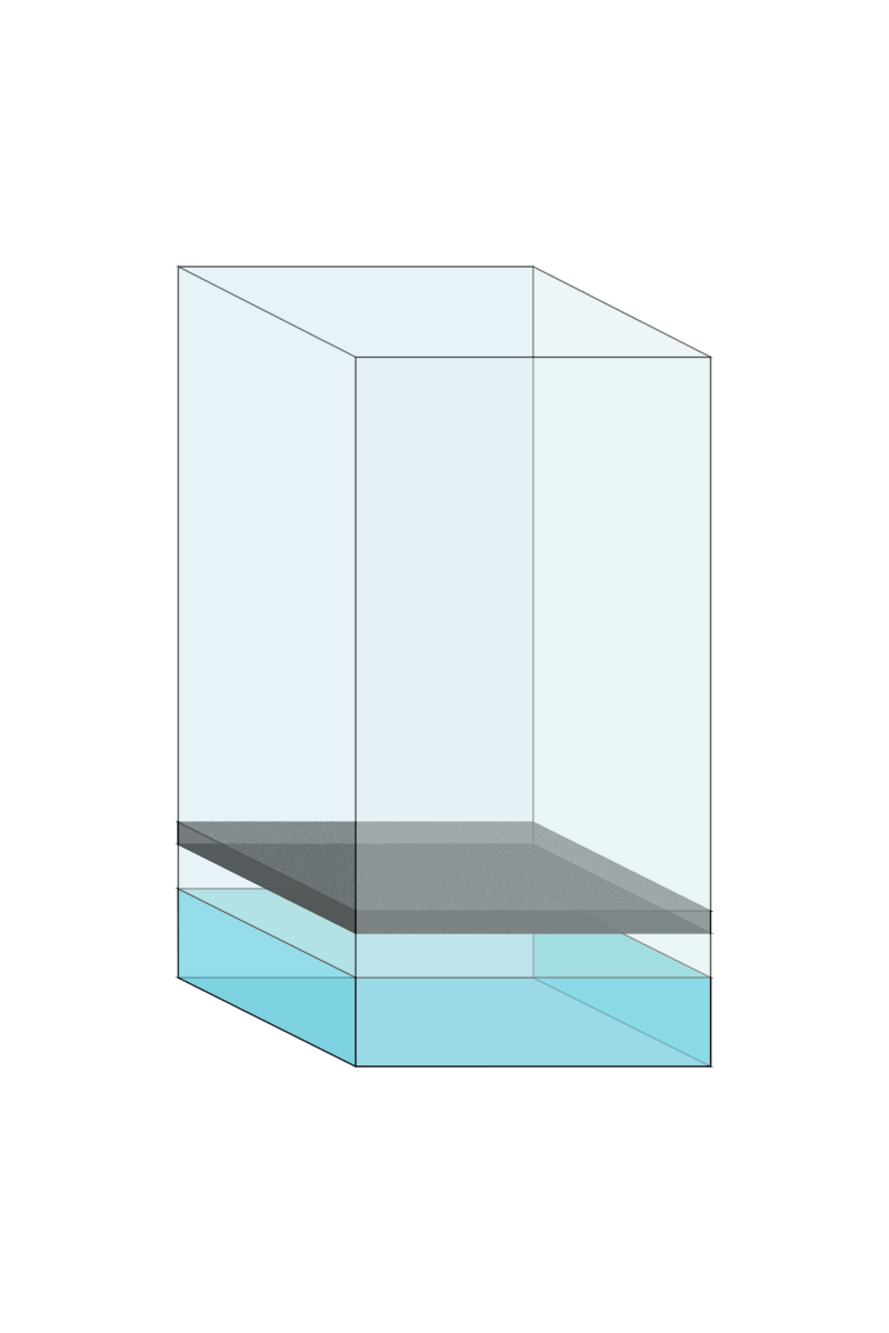
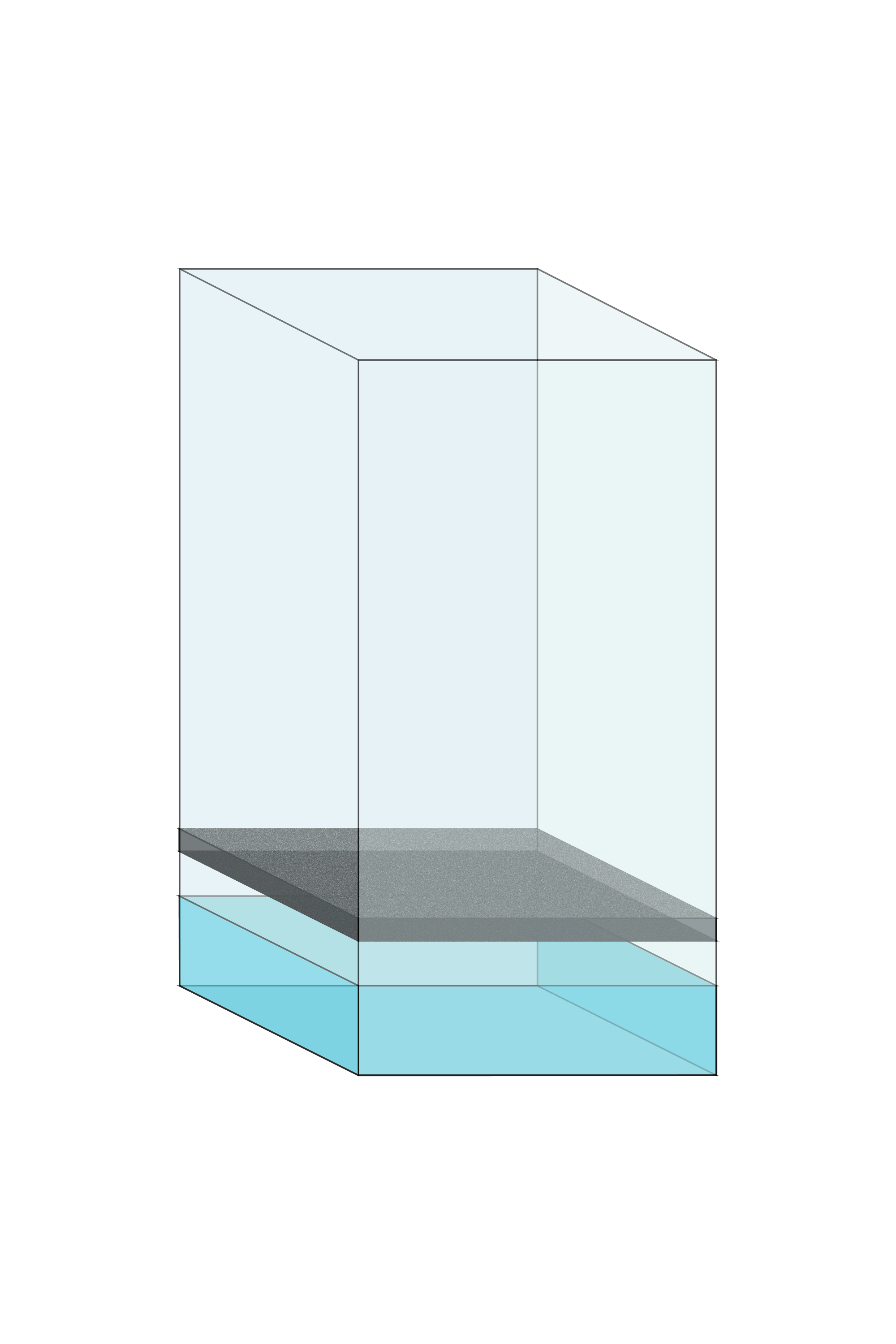
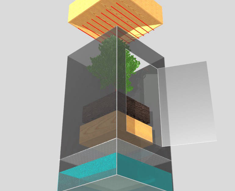
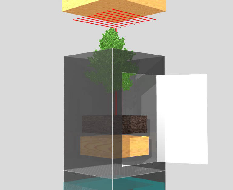
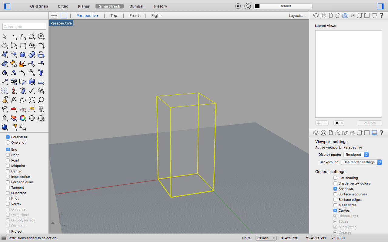
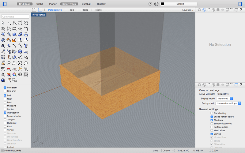
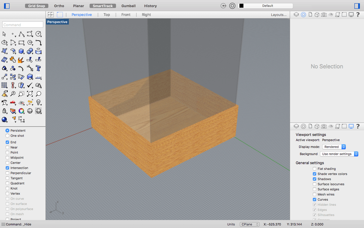
By double-clicking the screen, you can open the OBJECT MATERIAL window, in which you can choose the colors for the materials and different options you want to apply to them like transparency, color, gloss, or even add a texture from a JPEG or PNG image.
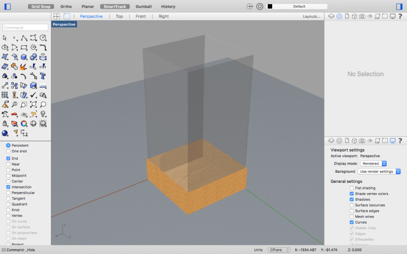
- 1 Base (620mm x 620mm).
- 2 Laterales (600mm x 200mm).
- 2 frontales y traseros (620mm x 200mm).
- 1 Base (620mm x 620mm).
- 2 Laterales (600mm x 200mm).
- 2 frontales y traseros (620mm x 200mm).
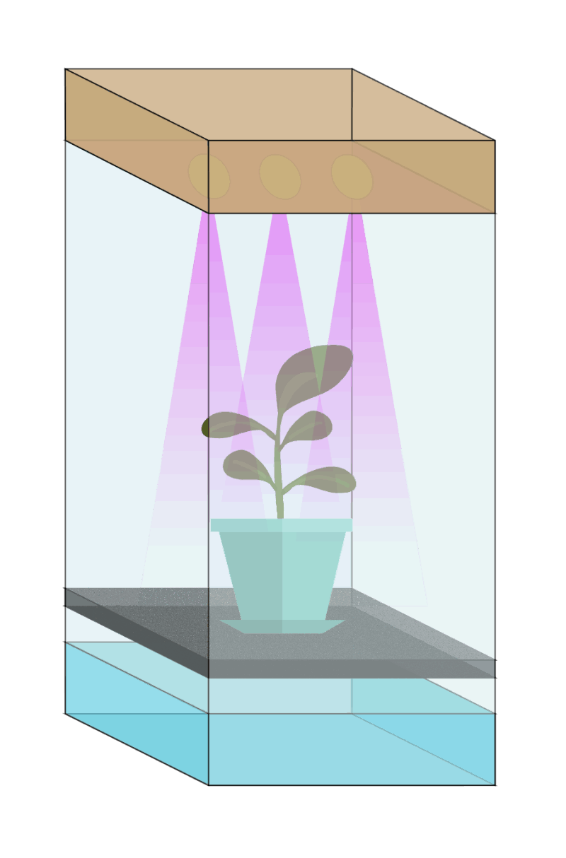
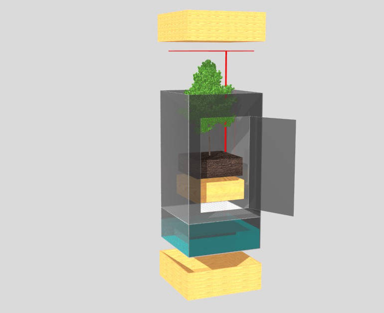
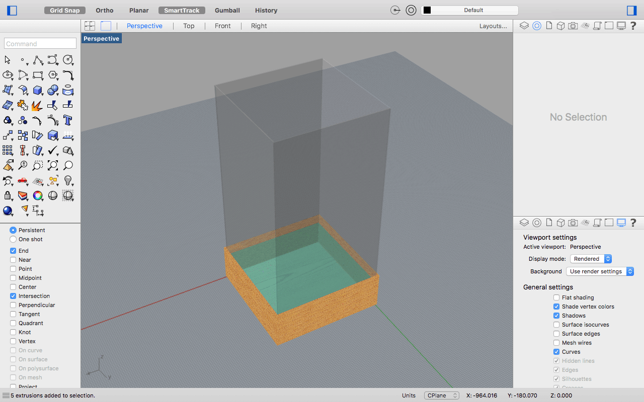
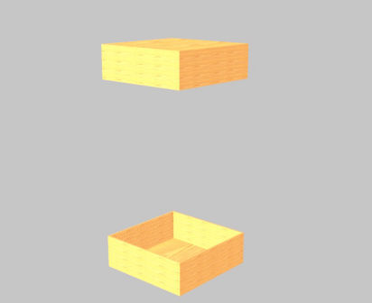
The top and the bottom part are exactly the same, but what changes is the possition and orientation.
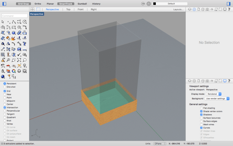
- 1 Base (590mm x 590mm).
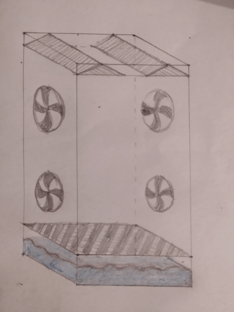
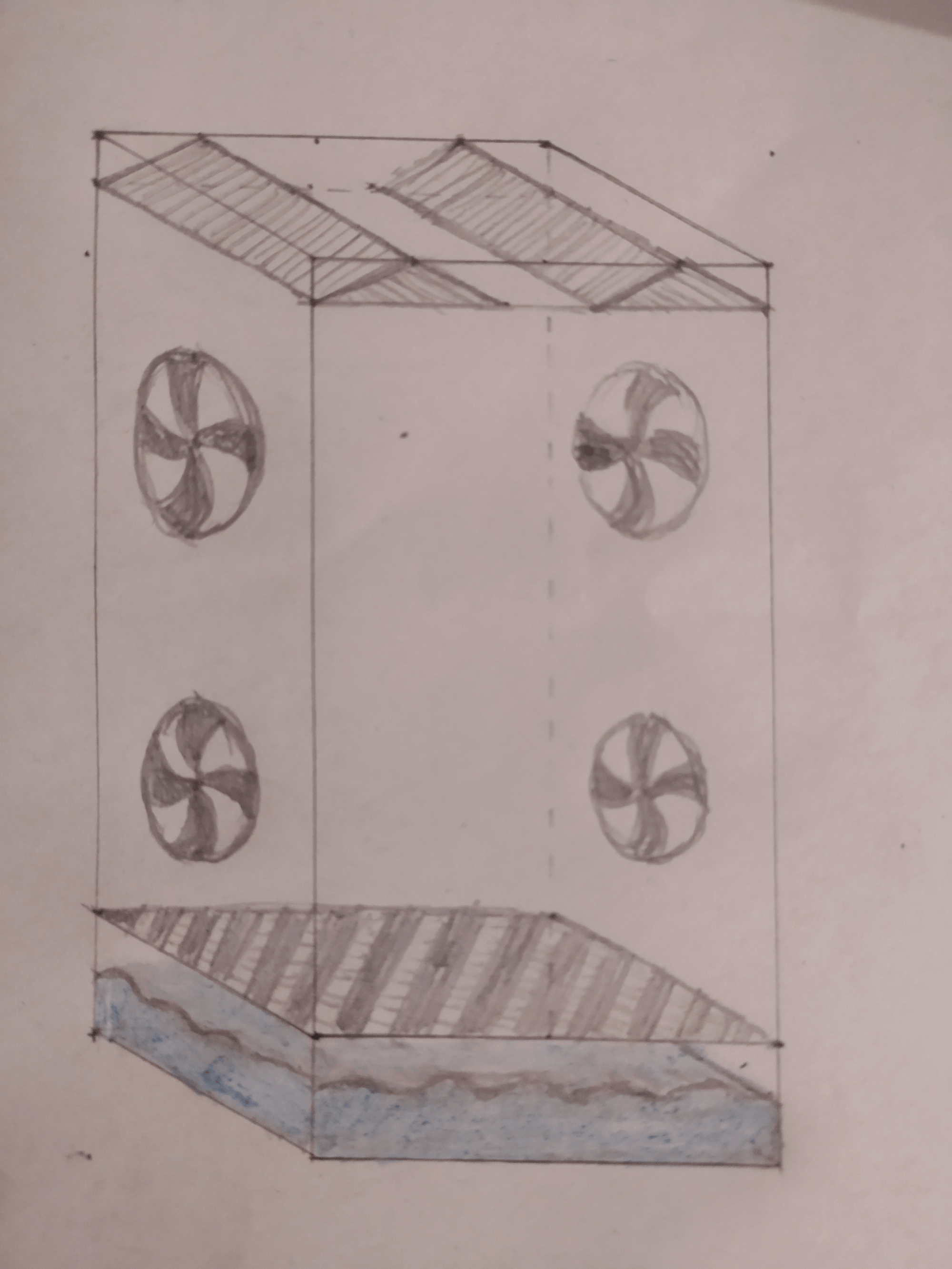
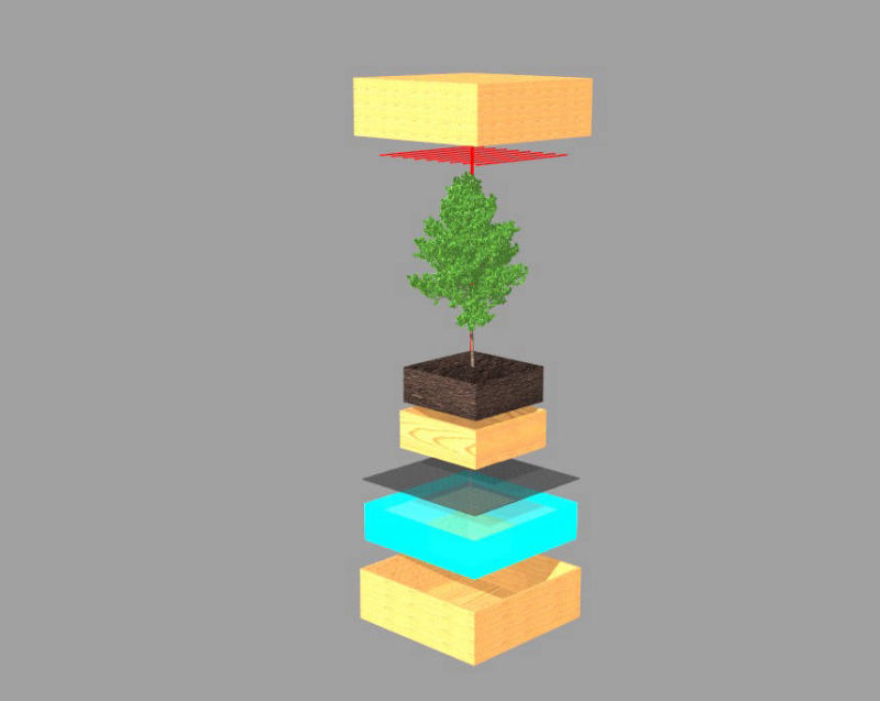
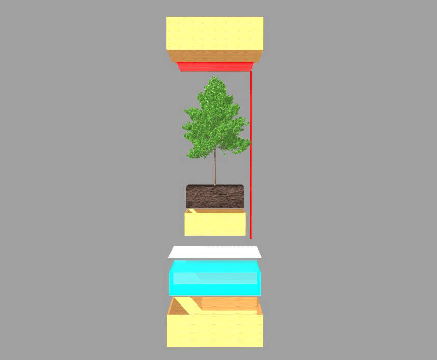
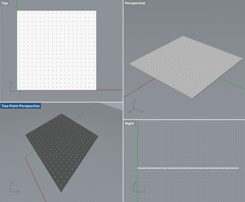
It´s an acrylic panel with lazer cutted holes of 5mm, with a 30 mm separation between them for the water to pass by into the bottom tank.
For this I created the base acrylic panel, and then created an array of cilinders with the RECTANGULAR ARRAY TOOL in Rhino by added the settings I wanted and started trying with the different measures so that the array fits the size. Then I extruded the material from the panel.
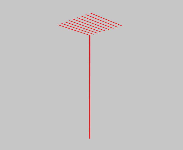
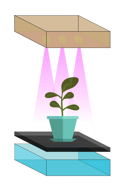
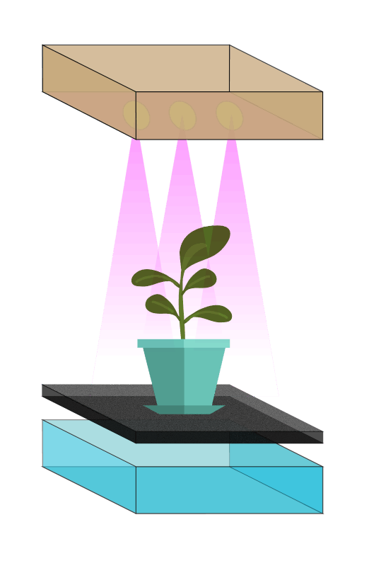
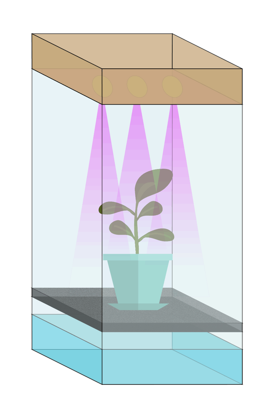
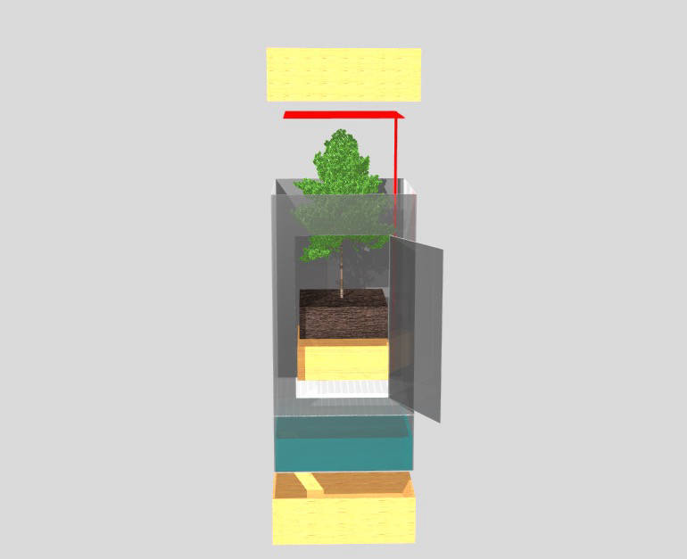
This would be the system that pumps tha water from the tank up, and drain it again above the plant.
For this I created a cilinder, extruded it and also used the RECTANGULAR ARRAY TOOL.

Mobirise free maker - Check this