Fab Academy 11

Output Devices

Servo Motor:

As an output device, I started trying to control a 9gr Micro Servo Motor with 180º movement. I wanted to controll a water pumo so that it would work for my experiment, but I was not able to get an externat battery source to control the pump through the delay, so I went instead with the servo.

ESP8266 12-E Chip Pinout

Tower Pro

Micro Servo

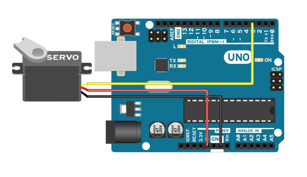
Tower Pro SG90 is an ideal servo motor for little mechanism. This one is comonly seen in RC vehicles and I saw it also works with PWM signal.

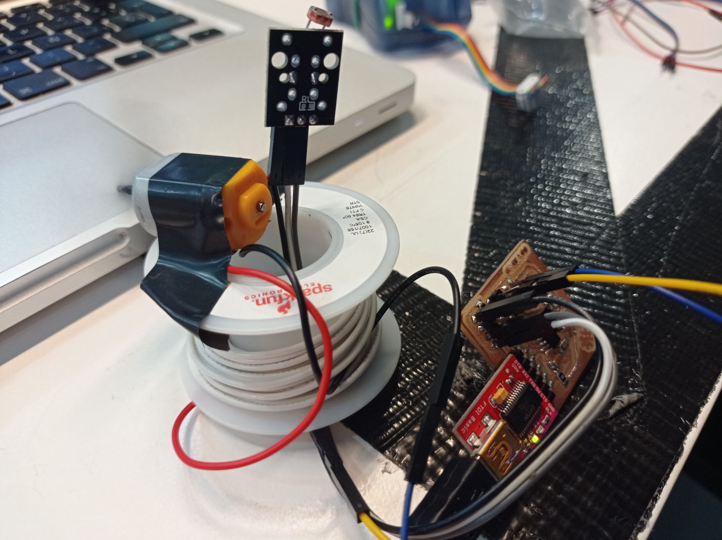
I have used it before, in a robotic arm project with 5 servos like this with acrylic body. To use the servo in arduino, you have to load the servo.h library at the begining of the code.


Technical Details:

Size: 23.1 mm x 12.2 mm x 29 mm
Working Voltage: 4.8-6v
Weight: 9 g
Speed at 4.8 V: 0.06 - 0.12 sec/60°
Compulsion Torque: 1.3 kg/cm
Torque: 0.06 - 0.12 sec/60°
Cable Lenght: 15 cm

Mobirise

SERVO CODE:

DESCRIPTION:

For this project I used a basic code found at https://www.instructables.com/, which: loads the library, declares the servo in pin 5, attaches it to the pin, and then move it to 0º, 90º and 180º positions, with a 1000 millisenconds delay between them.

#include <Servo.h>

int servoPin = 5;

Servo Servo1;

void setup() {
    Servo1.attach(servoPin);
}

void loop(){ 


    Servo1.write(0);
    delay(1000);

    Servo1.write(90);
    delay(1000);

    Servo1.write(180);
    delay(1000);
}

ESP8266 12-E Chip Pinout

HC-SR04

Ultrasonic Sensor

This is a ultrasonic sensor that has an emitter (Trigger) and a receiver (Echo) of ultrasonic signal, with which it can measure distances from 2 cm to 400 cm with a precision of 3 mm.

It works by sending a signal from your TRIGGER for a certain time (10ms), this signal bounces off an object and returns, and then the time the signal activates ECHO is measured. This time is then divided or multiplied in an equation related to the speed of sound, according to the desired unit of measurement (cms or inches).


Technical Details:

Dimensions:
45mm x 20mm x 15mm
Working voltage: DC 5V
Current consumption: 15 mA
Operating frequency: 40 Hz
Maximum visual range: 4m
Minimum viewing range: 2 cm
Visual angle: 15 °
Trigger foot input signal: 10 us TTL Pulse
Echo output signal: TTL input signal and distance ratio

Mobirise

HC-SR04 CODE:

DESCRIPTION:

For this project I used a basic code found at https://pimylifeup.com/, which basically measures a distance and prints it in the serial monitor.

int trigger_pin = 2;
int echo_pin = 3;
long distance, pulse_duration;

void setup() {

Serial.begin (9600);
pinMode(trigger_pin, OUTPUT);
pinMode(echo_pin, INPUT);
digitalWrite(trigger_pin, LOW);
}

void loop() { 

digitalWrite(trigger_pin, HIGH);
delayMicroseconds(10);
digitalWrite(trigger_pin, LOW);

pulse_duration = pulseIn(echo_pin, HIGH);
distance = round(pulse_duration * 0.0171);

Serial.print(distance);
Serial.print("cm");
Serial.println();

delay(500);
}

Troubleshooting

I had some troubles in the begging understanding the measurements of the sensor, because of the code I was using, so I looked for another tutorial that was more accurate and also compared it to a ruler to do a final calibration.

I also added an Average function after documenting it so that it doesn't takes into account the "noise" readings.

Mobirise

Light Reacting Motor

Since all of this documentation was during Lockdown, I compliment the examples with a DC motor controlled by an Pab-T-Tinny44 depending on the readings of an LDR sensor. The sensor also controls a Led integrated in the board.

The programing process was already described in the Inputs week, and I used the same code, but changed the actuator to be on the motor pin instead of one of the bulbs.

One of the problems I has was that the pins of the board don't give to much power, and apparently this motor needs a little bit more, so it might have been a good idea to add a mosfet and an external power source to the equation, so that we could PWM the mosfet while giving more power to the motor.

ESP8266 12-E Chip Pinout

CODE LINK:

#define LDR 2
#define Motor 7
#define GREEN 8

float LDRval = 0;
float sunny = 0; // calibrate sensor value WHEN LIGHT
float dark = 1024; // calibrate sensor value WHEN DARK
float treshold = 50; // define treshold to turn lights ON or OFF

#include

SoftwareSerial mySerial(0, 1); // RX, TX (0 y 1)

void setup() {

mySerial.begin(9600);

pinMode(LDR, INPUT);
pinMode(Motor, OUTPUT);
pinMode(GREEN, OUTPUT);
}

void loop() {

if (analogRead(LDR) < 500) {
digitalWrite(Motor,HIGH);
digitalWrite(GREEN,LOW);

} else {
digitalWrite(Motor,LOW);
digitalWrite(GREEN,HIGH);
}

LDRval = map(analogRead(LDR),sunny,dark,0,100);

mySerial.print("LDR Read: ");
mySerial.print(analogRead(LDR));
mySerial.print(" Light Percent: ");
mySerial.print(LDRval);
mySerial.println(" %");

}

Reflections and POWAR

As I was saying in the Inputs week, I like interacting within inputs, outputs and data from the cloud. So in my final project POWAR, I will actuate a water pump, a ventilator and a halogen lamp to simulate a weather inside, acording to the information gathered from a weather API on the web and the sensors inside of it.

Even dough, I suffered a lot programing these boards...

Voltio

Mobirise free creator - Learn more