10. Input Devices
1. Assignment && week workflow planning
1.1 Assignment requirements:
- Individual assignment:
measure something: add a sensor to a micro controller board that you have designed and read it
- Group assignment:
probe an input device’s analog levels and digital signals
The second half of the Fab Academy program is designed to build on the previous weeks. You will be synthesising information and implementing skills that you were introduced to in the first half of the program and encouraged to integrate these into your final project proposal
2. How i did it
2.0 HeroShot of the week
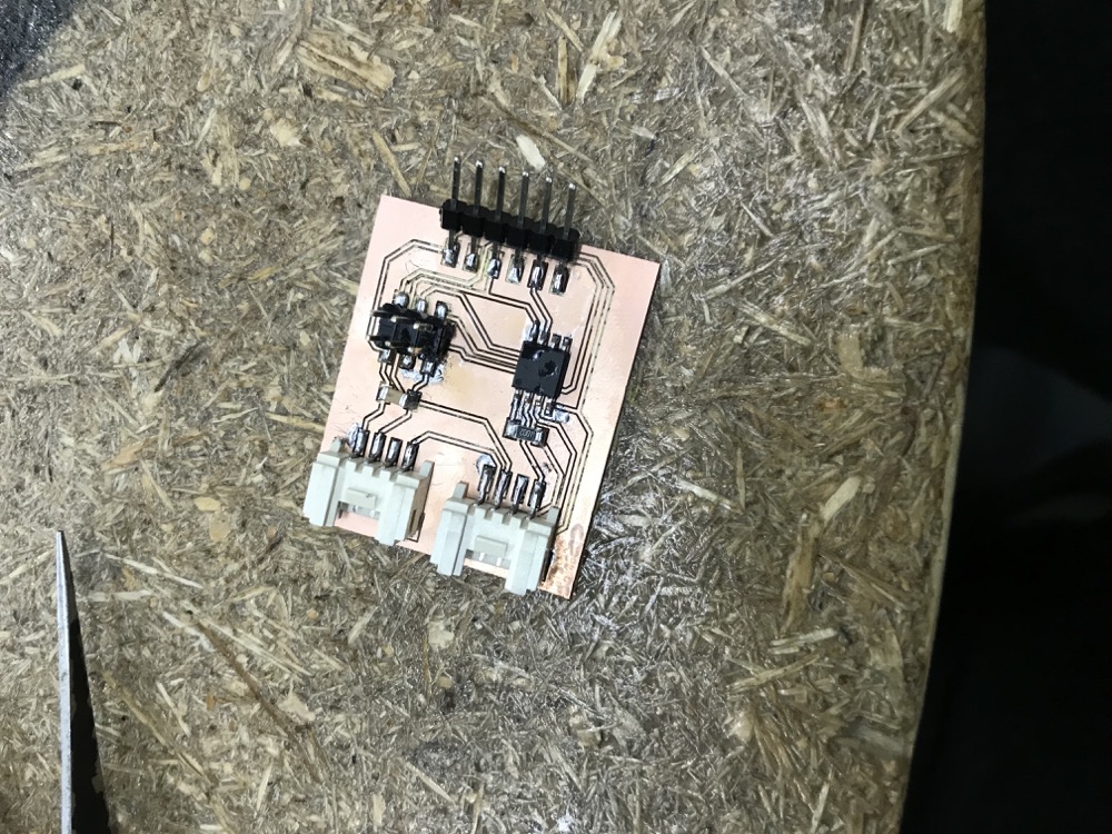
- The new board i made with 2 grove connectors
- Read temperature figure from DHT11
- Read distance figure from Ultrasonic sensor
2.1 Use an oscilloscope to probe an input device’s analog levels and digital signals for Group assignment
[GroupPage](groupLink
One probe of oscilloscope to go to GND of the input devices and another go to the signal(Data line that is transmitting data to microcontroller)
I tested the sound, light as analog levels
I tested the button, VCC for the digital signals
2.2 Read datasheet of sensors in order to understand how it talks to the microcontroller
- Air pressure(BMP280)
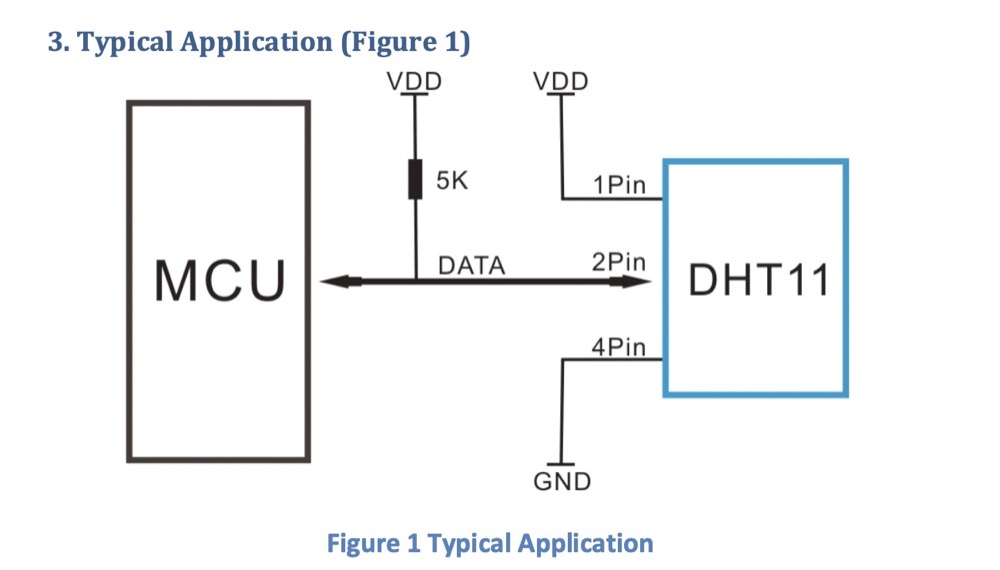
Temperature and Humidity(DHT11)
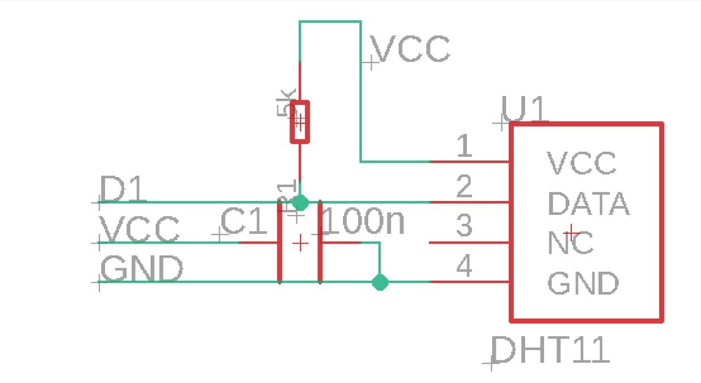
By reading the datasheet learned how DHT11 should connect to a MCU - use 1,2,4 pins as VCC,Data and GND. There is a 5K ohm resistor required.

- So the grove sensor connection in eagle should be
2.3 Design (a) sensor(s) built-in into my own board(Consider redesign my board to built-in sensors that needed for my final project)
-
Again to mention the feature i want my final project to have: 1)feed them in certain time in a day automatically(Motor,distance,motion) 2)feed them when i want(Wifi,Bluetooth,maybe i will need to redesign with ESP32? or SAMD?) 3)talk to them when i’m away(Speaker) 4)see them when i’m away(Camera) Motor, distance, motion, camera
Understand Pins, ADC, etc. -
Temperature to measure the house, Camera to see the dog, distance, motion for interaction
Attiny45 (MCU)
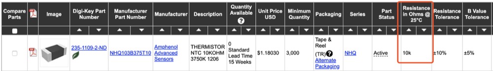
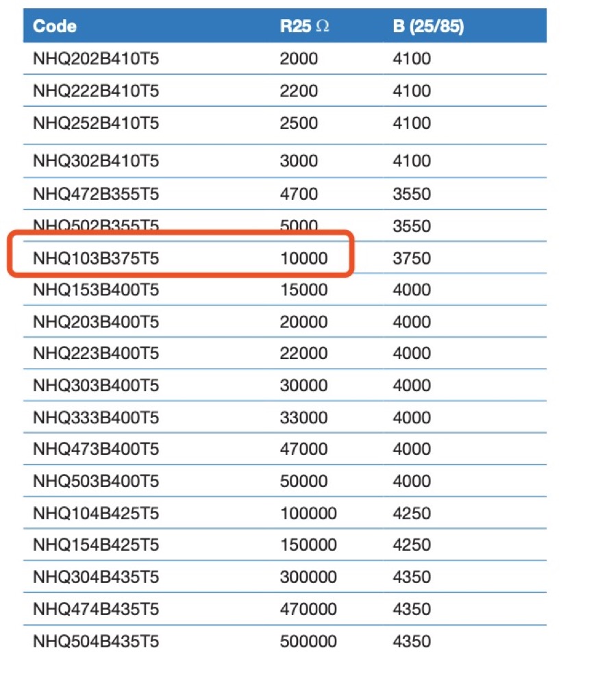
NTC temperature sensor (NHQ103B375T10)
- First of all understand how i may connect the temperature sensor to pins. Use eagle to draw the schematic.
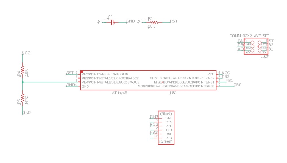
- Read the datasheet of NHQ103B375T10 and understand that i will need a 10k ohm resistor for it.
- I also want to leverage the resources as i’m working in Seeed, i have access to several hundreds of modular sensors and actuators. I can mount Grove interfaces on my board and use these tons of modular sensors in my projects.
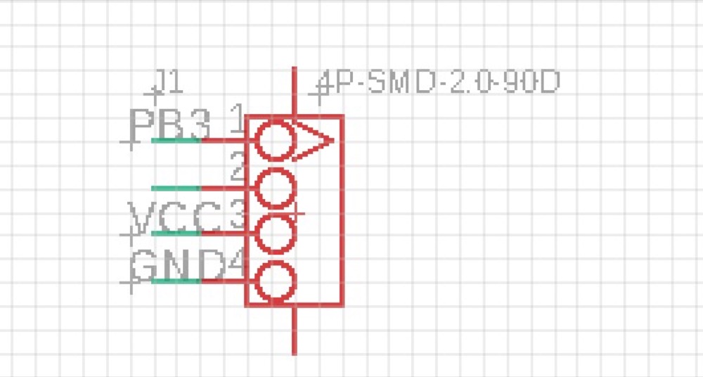
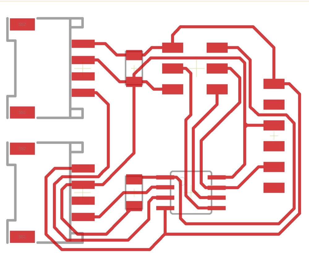
- I milled a board with 2 grove connectors, connected to PB3 and PB4, the 2 pins that are available.
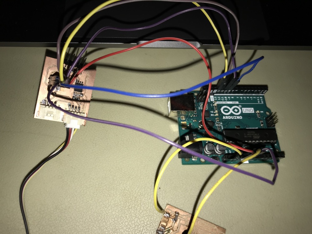
- Use Arduino as ISP to load the sketch.
- Writing the code - this one i used a FTDI cable to connect my board to the computer.
#include <SoftwareSerial.h>
SoftwareSerial mySerial(PB1,PB2);  //PB1 as RX, PB2 as TX

int pin = PB4;

void setup(void) {
pinMode(pin,INPUT);
  mySerial.begin(9600);
}
void loop(void) {
  int valueA = analogRead(pin);
  mySerial.println(valueA);
}
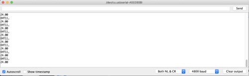
DHT11
First of All i downloaded the DHT library. The DHT library cannot have Serial parts in it as ATtiny doesn’t have a hardware Serial port.
I would connect the DHT11 to the PB4 pin. I defined 2 of my ports(PB1,PB2) as software Serial ports rx,tx.
I used Arduino as ISP to upload the sketch into my Attiny.
#include <SoftwareSerial.h>
#include <dht.h>


dht DHT;
#define DHT11_PIN PB4

SoftwareSerial softp(PB1,PB2);

void setup()
{
  softp.begin(4800);

}

void loop()
{
  // READ DATA
  softp.println("DHT11, \t");
  int chk = DHT.read11(DHT11_PIN);

  softp.println(DHT.temperature);

  delay(2000);
}
-
Then i unplugged the Arduino and connected my Attiny directly to computer through a FTDI converter. (PB2 from Attiny to Rx on converter, VCC and GND to each other corespondingly)Open up the Serial monitor from Arduino IDE, i would be able to read the DHT11 data sent from my Attiny45!
-
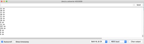
Likewise, i tried out the ultrasonic sensor
#include "Ultrasonic.h"
#include <SoftwareSerial.h>

Ultrasonic ultrasonic(PB4);
SoftwareSerial softp(PB1,PB2);

void setup() {
      softp.begin(4800);
}
void loop() {
    long RangeInCentimeters;

    RangeInCentimeters = ultrasonic.MeasureInCentimeters(); // two measurements should keep an interval
    softp.print(RangeInCentimeters);//0~400cm
    softp.println(" cm");
    delay(250);
}
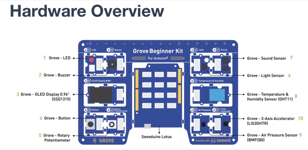
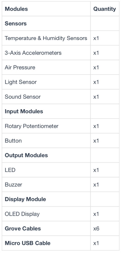
2.2 Go through all sensors using Grove Starter Kit For Arduino
For this kit i basically there’s no wiring needed as all the modules have been connected to the Seeeduino(Arduino Compatible board)through the PCB stamp holes.
| Modules | Interface | Pins/Address |
|---|---|---|
| LED | Digital | D4 |
| Buzzer | Digital | D5 |
| OLED Display 0.96” | I2C | I2C, 0x78(default) |
| Button | Digital | D6 |
| Rotary Potentiometer | Analog | A0 |
| Light | Analog | A6 |
| Sound | Analog | A2 |
| Temperature & Humidity Sensor | Digital | D3 |
| Air Pressure Sensor | I2C | I2C, 0x77(default) / 0x76(optional) |
| 3-Axis Accelerator | I2C | I2C, 0x63(default) |
Powered it up, long press the button exiting the current mode and went to different mode(different sensors) to give it a basic try.
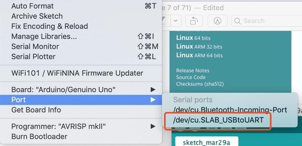
When i wanted to program it with Arduino IDE, the first problem i met with was that my computer didn’t find my device(the port in Arduino IDE not showing up). I guess it was the driver issue so i downloaded the USB to UART driver. Tried again and it worked.
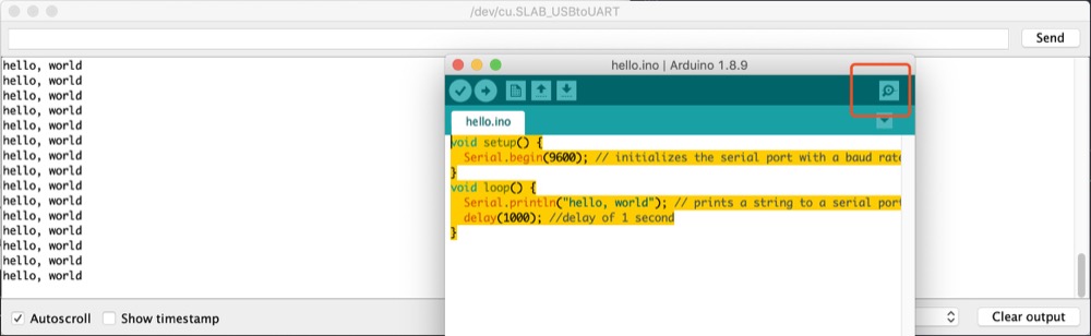
Using built-in Arduino Serial Monitor to print “hello, world”
void setup() {
  Serial.begin(9600); // initializes the serial port with a baud rate of 9600
}
void loop() {
  Serial.println("hello, world"); // prints a string to a serial port
  delay(1000); //delay of 1 second
}
- Blinking LED (OutputDevice)
1.1 with Button control(Digital Input)
int ledPin = 4;
int button = 6;

void setup() {
    pinMode(ledPin, OUTPUT);
    pinMode(button,INPUT);
}
void loop() {
  if(digitalRead(button) == HIGH)
  {
    digitalWrite(ledPin, HIGH);
    delay(1000);
    digitalWrite(ledPin, LOW);
    delay(1000);
  }
  else digitalWrite(ledPin,LOW);
}
1.2 With Rotary Switch control(Analog Input)
int ledPin = 4;
int rotaryPin = A0;

void setup() {
    pinMode(ledPin, OUTPUT);
    pinMode(rotaryPin,INPUT);
}
void loop() {
  digitalWrite(ledPin,HIGH);
  delay(analogRead(rotaryPin));
  digitalWrite(ledPin,LOW);
  delay(analogRead(rotaryPin));

}
- Buzzer(OutPutDevice)
PWM output is needed to control the volumn of the beep sound. There are 6 PWM pins on Seeeduino that can send out PWM signal: 3,5,6,9,10,11.
int BuzzerPin = 5;
int Potentiometer = A0;
void setup() {
  pinMode(BuzzerPin, OUTPUT);
}
void loop() {
  int potentioValue, Value;
  potentioValue = analogRead(Potentiometer);
  Value = map(potentioValue, 0, 1023, 0, 255); //Mapping potentiometer value to PWM signal value
  analogWrite(BuzzerPin, Value);
}
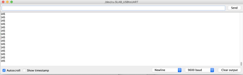
- Light sensor Induct LED
When it is dark, then the LED will be on; When it is bright the LED will be off.
The Serial Monitor printed out the sensorvalue
int sensorpin = A1;
int ledPin = 4;
int sensorValue = 0;
int outputValue = 0;
void setup() {
  pinMode(ledPin,OUTPUT);
  Serial.begin(9600);
}

void loop() {
  sensorValue = analogRead(sensorpin);
  outputValue = map(sensorValue, 0, 145, 255,0);
  Serial.println(sensorValue);
  analogWrite(ledPin, outputValue);
  delay(30);
}
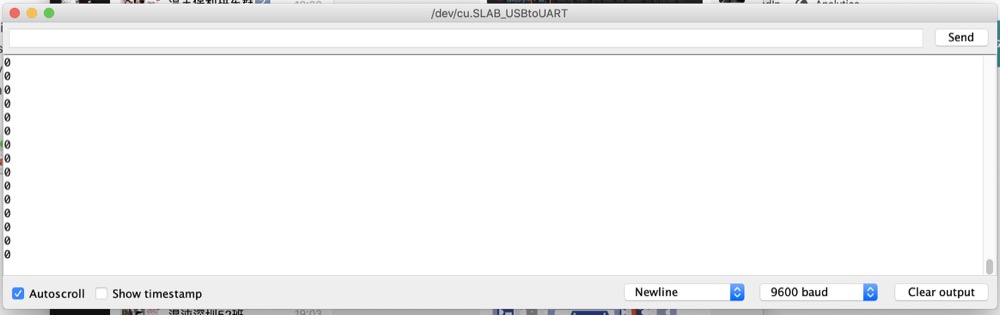
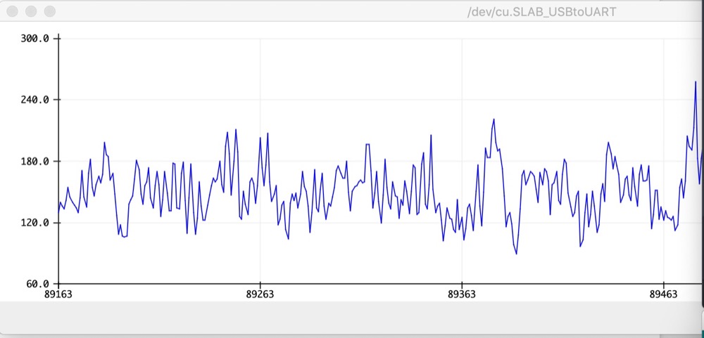
- Sound sensor induct LED
When the sound is loud, lights on. Oppositely, off. Serial Potter watch the soundpin input.
//Sound Control Light
int soundPin = A2;
int ledPin = 4;
void setup() {
  pinMode(ledPin, OUTPUT);
  Serial.begin(9600);
}
void loop(){
  int soundState = analogRead(soundPin); // Read sound sensor’s value
  Serial.println(soundState);
  if (soundState > 300) {
    digitalWrite(ledPin, HIGH);
    delay(100);
  }else{
    digitalWrite(ledPin, LOW);
  }
}
- Displaying Data
Needed to include another Library “U8g2” to Arduino by: Navigate to Sketch -> Include Library -> Manage Libraries… and Search for the keyword “U8g2” in the Library Manager, then install.
Used the default example with tiny modification Print “Fab2020” on the OLED screen
#include <Arduino.h>
#include <U8x8lib.h>
U8X8_SSD1306_128X64_ALT0_HW_I2C u8x8(/* reset=*/ U8X8_PIN_NONE);
void setup(void) {
  u8x8.begin();
  u8x8.setFlipMode(1);
}
void loop(void) {
  u8x8.setFont(u8x8_font_chroma48medium8_r);
  u8x8.setCursor(0,0);
  u8x8.print("Fab2020");
}
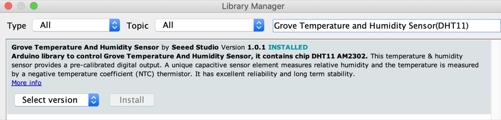
- Detecting Temperature and Humidity
Install the temperatur(DHT11) library “Grove Temperature and Humidity Sensor(DHT11)”
Copy and paste the code example
//Temperature and Humidity Sensor
//Temperature and Humidity Sensor
#include "DHT.h"
#include <Arduino.h>
#include <U8x8lib.h>
#define DHTPIN 3     // what pin we're connected to
#define DHTTYPE DHT11   // DHT 11
DHT dht(DHTPIN, DHTTYPE);
U8X8_SSD1306_128X64_ALT0_HW_I2C u8x8(/* reset=*/ U8X8_PIN_NONE);
void setup(void) {
  Serial.begin(9600);
  Serial.println("DHTxx test!");
  dht.begin();
  u8x8.begin();
  u8x8.setPowerSave(0);
  u8x8.setFlipMode(1);
}
void loop(void) {
  float temp, humi;
  temp = dht.readTemperature();
  humi = dht.readHumidity();
  u8x8.setFont(u8x8_font_chroma48medium8_r);
  u8x8.setCursor(0, 33);
  u8x8.print("Temp:");
  u8x8.print(temp);
  u8x8.print("C");
  u8x8.setCursor(0,50);
  u8x8.print("Humidity:");
  u8x8.print(humi);
  u8x8.print("%");
  u8x8.refreshDisplay();
  delay(200);
}
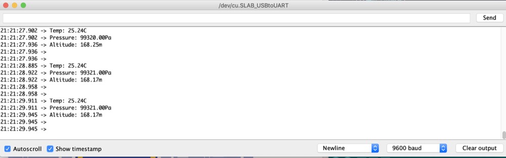
- Air Pressure(BMP280)
Again install library for BMP280 “Grove BMP280”
//Air pressure detection
#include "Seeed_BMP280.h"
#include <Wire.h>
BMP280 bmp280;


void setup() {
    Serial.begin(9600);
    if (!bmp280.init()) {
        Serial.println("Device not connected or broken!");
    }
}
void loop() {
    float pressure;
    //get and print temperatures
    Serial.print("Temp: ");
    Serial.print(bmp280.getTemperature());
    Serial.println("C"); // The unit for  Celsius because original arduino don't support speical symbols
    //get and print atmospheric pressure data
    Serial.print("Pressure: ");
    Serial.print(pressure = bmp280.getPressure());
    Serial.println("Pa");
    //get and print altitude data
    Serial.print("Altitude: ");
    Serial.print(bmp280.calcAltitude(pressure));
    Serial.println("m");
    Serial.println("\n");//add a line between output of different times.
    delay(1000);
}
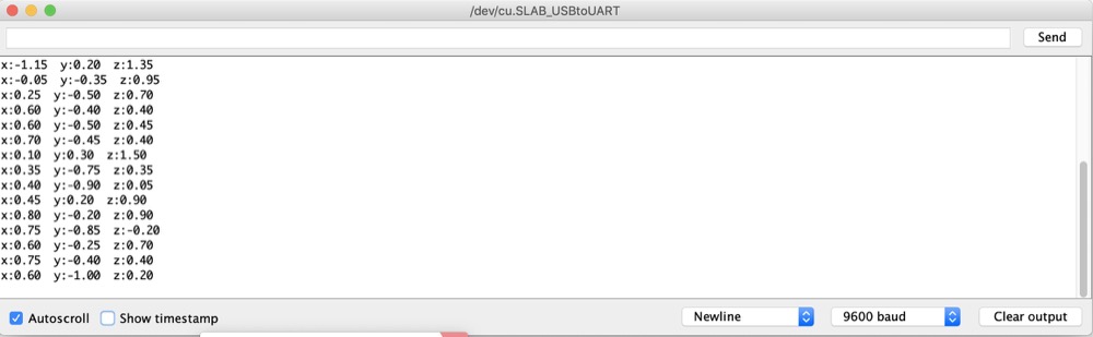
- 3-Axis Accelerometer
Install library from Github.Sketch > Include library > Add .ZIP library, import the library into the IDE.
//Gravity Acceleration
#include "LIS3DHTR.h"
#ifdef SOFTWAREWIRE
    #include <SoftwareWire.h>
    SoftwareWire myWire(3, 2);
    LIS3DHTR<SoftwareWire> LIS(I2C_MODE);//IIC
    #define WIRE myWire
#else
    #include <Wire.h>
    LIS3DHTR<TwoWire> LIS(I2C_MODE);//IIC
    #define WIRE Wire
#endif
void setup() {
    Serial.begin(9600);
    while (!Serial) {};
    LIS.begin(WIRE); //IIC init
    delay(100);
    LIS.setOutputDataRate(LIS3DHTR_DATARATE_50HZ);
}
void loop() {
    if (!LIS) {
        Serial.println("LIS3DHTR didn't connect.");
        while (1);
        return;
}
//3 axis
    Serial.print("x:"); Serial.print(LIS.getAccelerationX()); Serial.prin
t("  ");
    Serial.print("y:"); Serial.print(LIS.getAccelerationY()); Serial.prin
t("  ");
    Serial.print("z:"); Serial.println(LIS.getAccelerationZ());
    delay(500);
}