Final Project
1. Preparation
1.1 Final Project Requirement
- Document a final project masterpiece that integrates the range of units covered, answering:
What does it do? -> Answered
Who’s done what beforehand? -> N/A
What did you design? -> Answered
What materials and components were used? -> Answered
Where did they come from? -> Answered
How much did they cost? -> Answered
What parts and systems were made? -> Answered
What processes were used? -> Answered
What questions were answered? -> Answered
What worked? What didn’t? -> Answered
How was it evaluated? -> Answered
What are the implications? -> Answered
-
Prepare a summary slide and a one minute video showing its conception, construction, and operation
-
Your project should incorporate 2D and 3D design,additive and subtractive fabrication processes, electronics design and production, embedded microcontroller interfacing and programming, system integration and packaging
-
Where possible, you should make rather than buy the parts of your project
-
Projects can be separate or joint, but need to show individual mastery of the skills, and be independently operable
-
Present your final project, weekly and group assignments, and documentation
1.2 Where the idea comes from?
It is maybe a pain in the ass for most of the dogs’ parents - that you can’t pet them nicely during you are out for work.
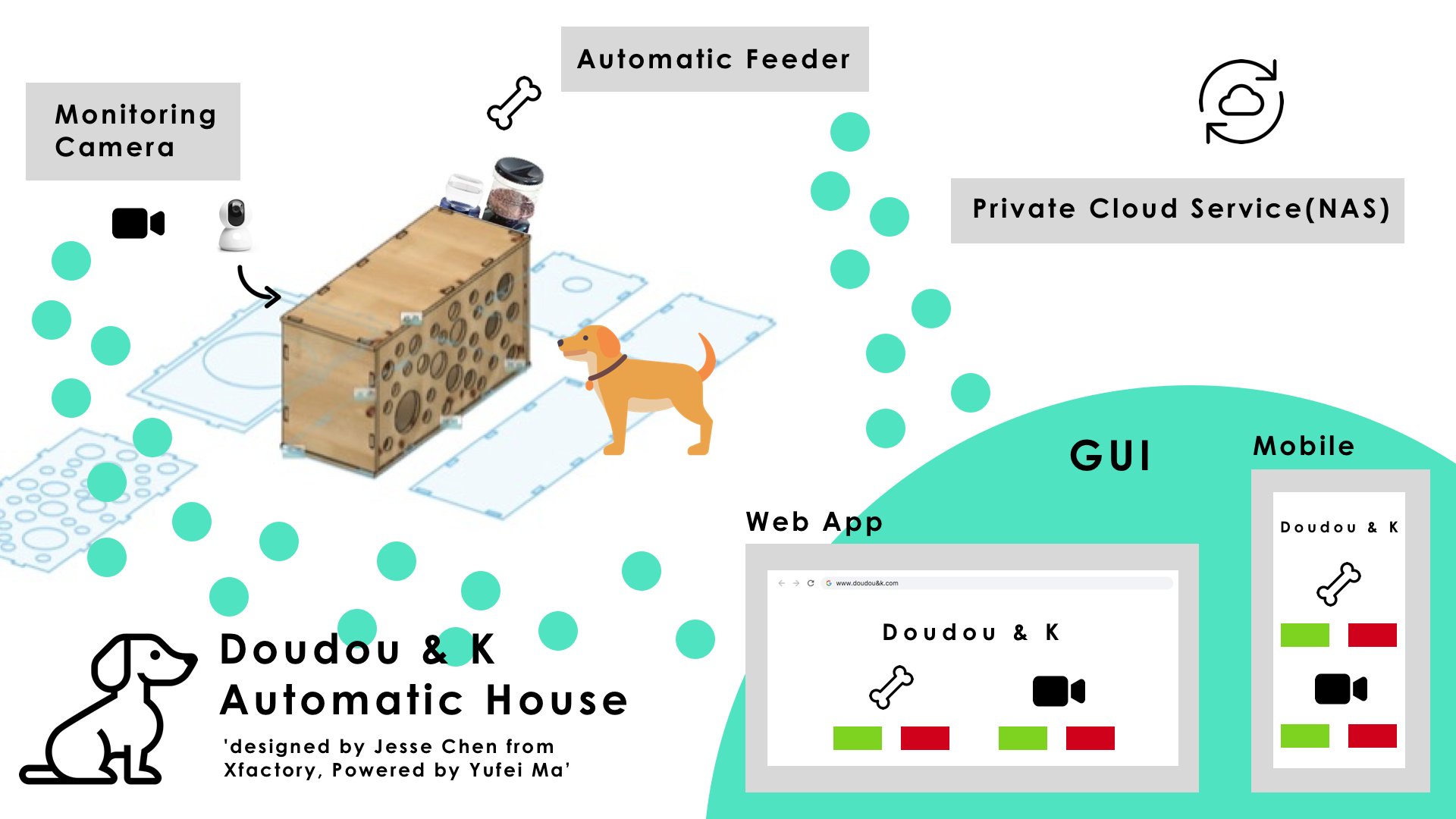
I want to somehow make a device have parents interacting with their puppies during parents’ absence - I would give the project a name: Smart_Puppy_House.
Smart_Puppy_House has a nice house made of wood, with its top as a sofa, where parents can sitting on it while puppies are sleeping underneath.
Smart_Puppy_House has one floor, with bed of course but also a Built_In automatic feeding system.
I’m talking about a feeding system that can
- feed puppies in certain time in a day automatically
- feed them when parents want to
Smart_Puppy_House has also some interacting units
- Parents can talk to puppies when they are away
- Parents are able to see what puppies are doing when they are away
1.3 How i plan my workflow
For sensors and actuators, i will leverage my resources working at Seeed that to use the grove modules together with my designed board.
I plan to use an ESP32 or SAMD51 microcontroller for my final project, as those Chips have
- Embeded Wifi and bluetooth
- more I/O pins for input and output devices,
- plus they both have RTC built-in which is nice.
I will design my circuit built in many grove connectors for further usages with grove modules.
Temperature&Humidity sensor + OLED Display to detect and display the temp and Humidity situations inside the Smart_Puppy_House.
Ultrasonic sensor
Camera as input device to make me able to see puppies through a mobile device remotely
Speaker as output device to make puppies hear me when i am talking through a mobile device remotely.
RTC to tell my board the time and thus my board know when to drop the food in a day.
Wifi on my board connected to the router in order to communicate back and forth over the internet with me.
BlE - i think i would need the function but i not yet know where exactly i need it for.
Software interface on mobile phone to send instructions and receive information to and from my Smart_Puppy_House
2. How i did it
2.0 HeroShot
2.1 Materials
Mandentory:
| Qty | Description | Price |
|---|---|---|
| 1 | ESP32-WROOM-32 | $3.8 |
| 1 | 16.8mm thickness wood for the puppy house | N/A |
| 1 | 3mm thickness basewood for the dispenser | N/A |
| 1 | EMAX 9g ES08A servo | $9.9 |
| 1 | Double-Sided Tape | $2.0 |
| 1X10pcs | 4pin_Grove connectors | $1.5 |
Optional:
| Qty | Description | Price |
|---|---|---|
| 1 | Grove - Temperature & Humidity Sensor (DHT11) | $5.9 |
| 1 | Grove - Serial Camera Kit | $29.9 |
| 1 | Grove - Ultrasonic Distance Sensor | $3.9 |
| 1 | Grove - Speaker | $6.9 |
2.2 Structure for Smart House and the dispenser
2.2.1 House
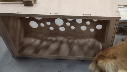
For the house i’ve designed and made it week8(the Computer controlled machining week).
2.2.2 Dispenser
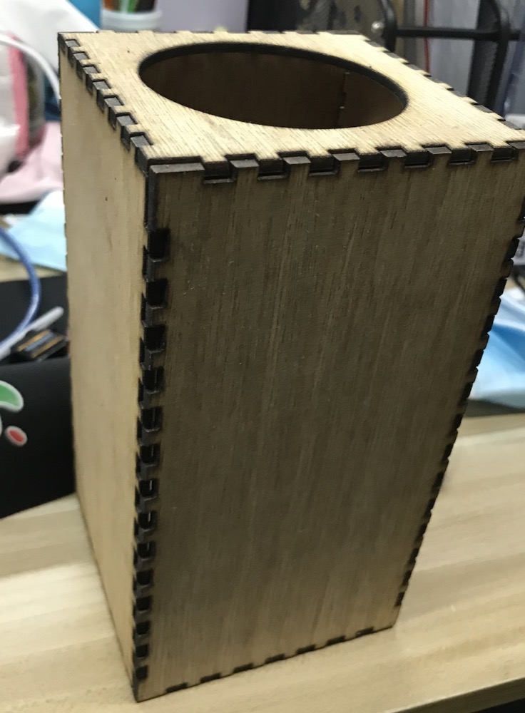
-
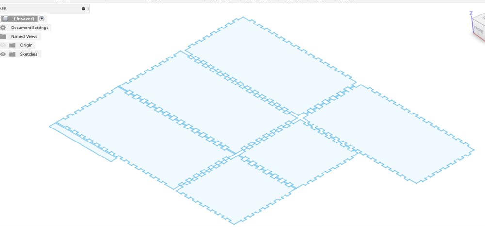
Download a reference design from here in .dxf format and set parameter
Dimension: 190mm100mm100mm
Thickness: 3mm
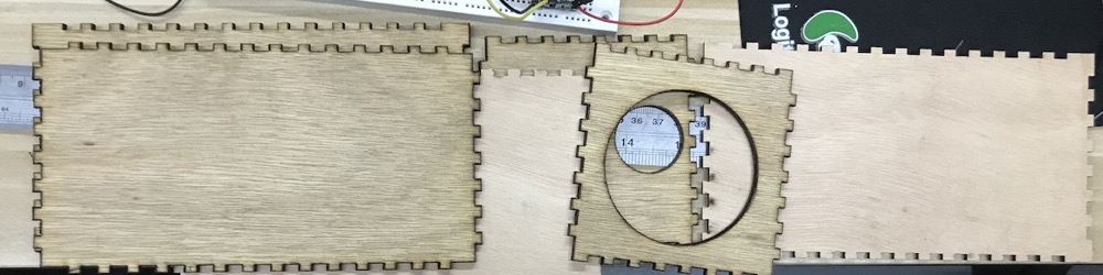
- Try assemble it
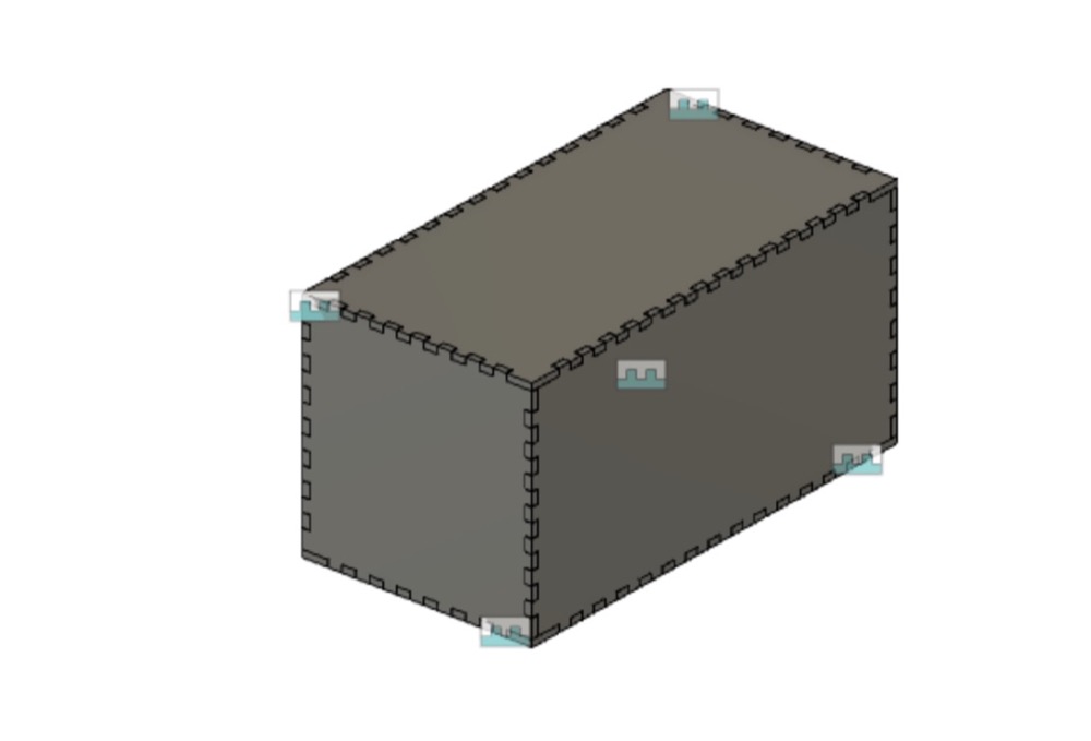
- Modify the box and finally
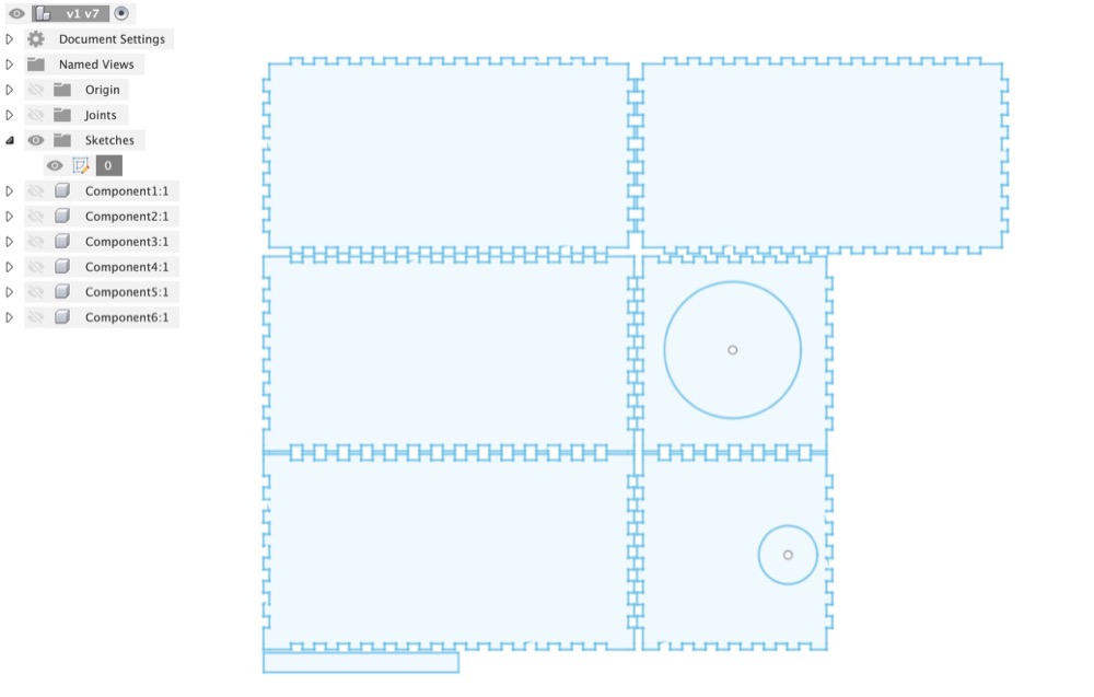
- LaserCut and assembling
2.3 Automatic feeder
I will use a ESP32 module and design a circuit with 4-6 standard grove interfaces built-in, which i will use for the Camera, Temperature&Humidity, Ultrasonic sensors as input, and a OLED display, Speaker, motor as output devices.
2.3.1 Eletronic design && manufacture
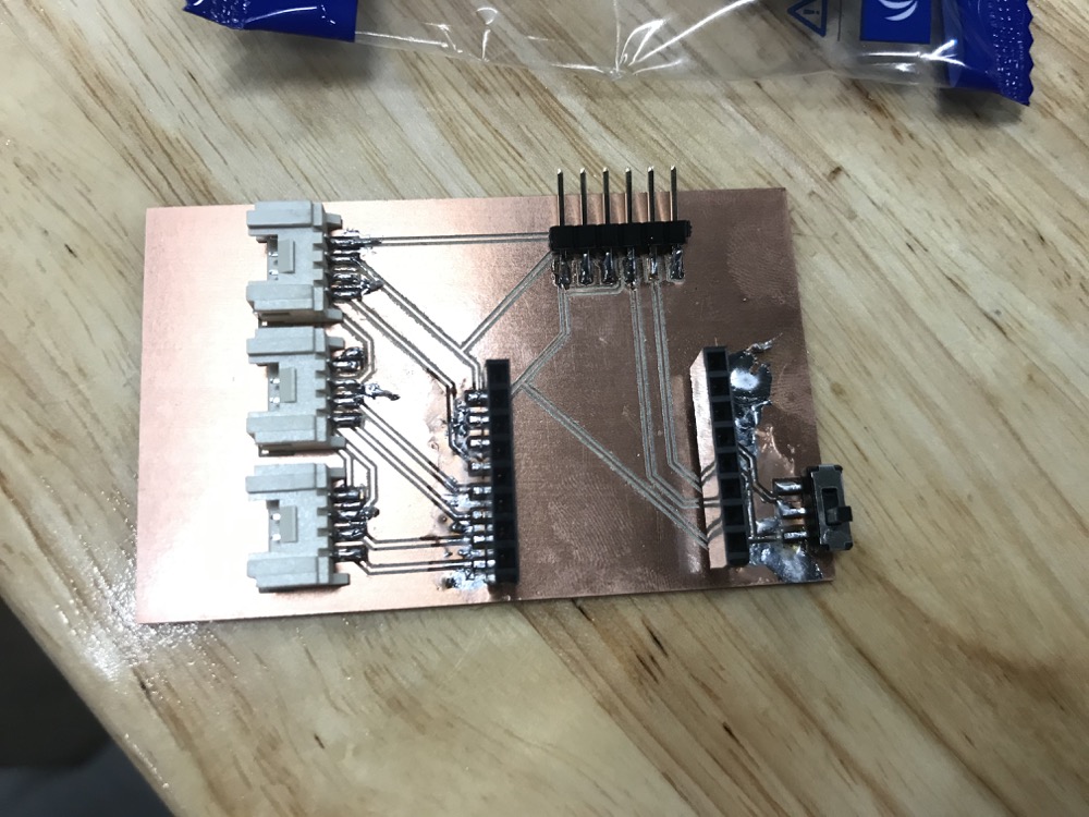
- I designed the ESP32 circuit and milled the board at Week14
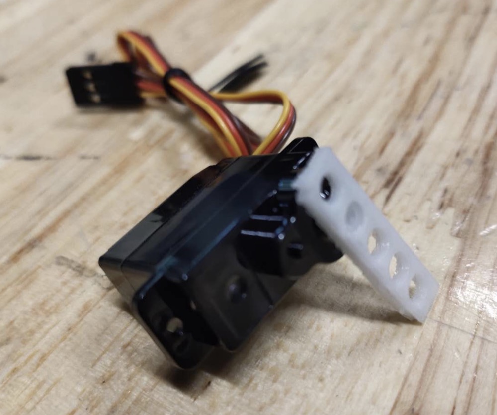
2.3.2 Use my ESP32-CAM to control a servo
-
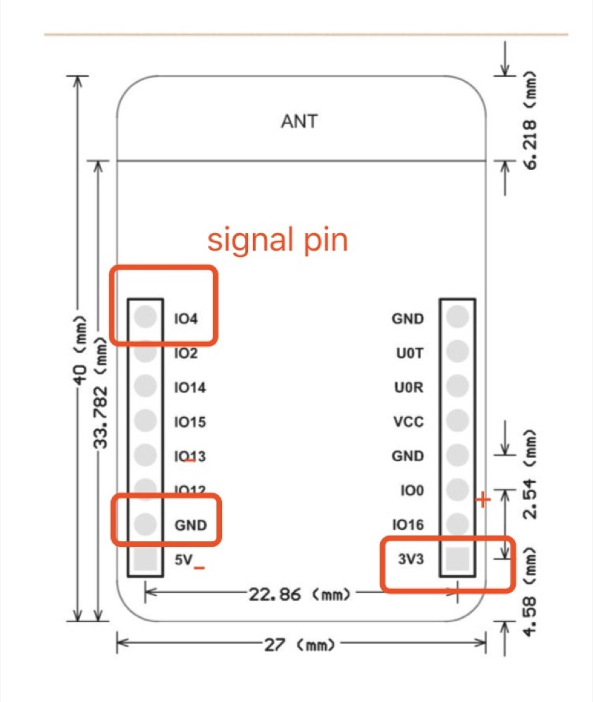
I’m using EMAX 9g ES08A servo. The location of each pin: red (+),brown (-), yellow (signal).
-
Connect to my ESP32 and using IO4 as the signal pin
-
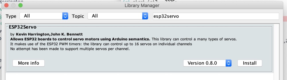
Download and include the servo library i found on github
-
Download another library from directly the Arduino library
- Use example to do a trial run of the servo
Note that the ESP32-CAM i’m using, to upload code will need to do the same configuration as i do in the [network week].
Codes as below
#include <Servo.h>

static const int servoPin = 4;

Servo servo1;

void setup() {
    Serial.begin(115200);
    servo1.attach(servoPin);
}

void loop() {
    for(int posDegrees = 0; posDegrees <= 180; posDegrees++) {
        servo1.write(posDegrees);
        Serial.println(posDegrees);
        delay(20);
    }

    for(int posDegrees = 180; posDegrees >= 0; posDegrees--) {
        servo1.write(posDegrees);
        Serial.println(posDegrees);
        delay(20);
    }
}
2.3.3 Configure the Built_In RTC on board
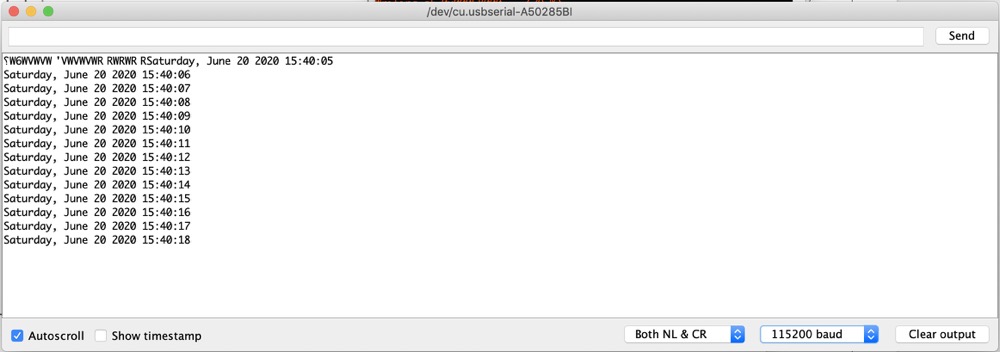
- run the example
2.3.4 Program to make servo run automatically according to the time
- When the time approaches 1200 and 1800, then the servo run 180 degree and delay for 15ms and go back. Code as following
#include <WiFi.h>
#include "time.h"

const char* ssid       = "x.factory";
const char* password   = "xxxxxx";

const char* ntpServer = "pool.ntp.org";
const long  gmtOffset_sec = 28800;//东八区时间
const int   daylightOffset_sec = 0;

//$---------#add 设置闪光灯引脚为4------------
#define LED_PIN 4

//$--------#add 时间检测----------------
bool isCheck = false;
int start_int = 1800;
int start_int2 = 1200;

//$--------#add 伺服电机----------------
#include <ESP32Servo.h>
Servo myservo;  // create servo object to control a servo
// 16 servo objects can be created on the ESP32
int pos = 0;    // variable to store the servo position
// Recommended PWM GPIO pins on the ESP32 include 2,4,12-19,21-23,25-27,32-33
int servoPin = 2;


void printLocalTime()
{
  struct tm timeinfo;
  if (!getLocalTime(&timeinfo)) {
    Serial.println("Failed to obtain time");
    return;
  }
  Serial.println(&timeinfo, "%A, %B %d %Y %H:%M:%S");

}
//$--------#add 获取时间整数----------------
int getTimeInt()
{
  struct tm timeinfo;
  //  int time_int;
  if (!getLocalTime(&timeinfo)) {
    Serial.println("Failed to obtain time");
    return 0;
  }
  Serial.println(&timeinfo, "%A, %B %d %Y %H:%M:%S");
  int hour_int = timeinfo.tm_hour;
  int min_int = timeinfo.tm_min;


  String time_string = int2String(hour_int) + int2String(min_int);
  int time_int = time_string.toInt();
  Serial.println("time_int: " + String(time_int));
  return time_int;
}
//$--------#add 将小于10的整数加0,并变为字符串----------------
String int2String(int the_time_int) {
  String the_time_string;
  if (the_time_int < 10) {
    the_time_string = "0" + String(the_time_int);
  } else {
    the_time_string = String(the_time_int);
  }
  return the_time_string;
}

void setup()
{
  Serial.begin(115200);

  //connect to WiFi
  Serial.printf("Connecting to %s ", ssid);
  WiFi.begin(ssid, password);
  while (WiFi.status() != WL_CONNECTED) {
    delay(500);
    Serial.print(".");
  }
  Serial.println(" CONNECTED");

  //init and get the time
  configTime(gmtOffset_sec, daylightOffset_sec, ntpServer);
  printLocalTime();

  //disconnect WiFi as it's no longer needed
  WiFi.disconnect(true);
  WiFi.mode(WIFI_OFF);

  //$-------#add 设置闪光灯灯引脚 --------
  pinMode(LED_PIN, OUTPUT);

  //$--------#add 伺服电机----------------
  myservo.setPeriodHertz(50);    // standard 50 hz servo
  myservo.attach(servoPin, 1000, 2000); // attaches the servo on pin 18 to the servo object
}

void loop()
{
  delay(1000);
  //  printLocalTime();
  int time_int = getTimeInt();
  //$---------根据是否到达时间,进行处理--------
  if (time_int == start_int || time_int == start_int2) {
    //$---------根据之前是否执行任务,进行处理--------
    if (isCheck) {
      Serial.println("has check");
    } else {
      Serial.println("light on");
      digitalWrite(LED_PIN, HIGH);
      isCheck = true;
      //$--------------电机转动----------------v
      for (pos = 0; pos <= 180; pos += 1) { // goes from 0 degrees to 180 degrees
        // in steps of 1 degree
        myservo.write(pos);    // tell servo to go to position in variable 'pos'
        delay(15);             // waits 15ms for the servo to reach the position
      }
      for (pos = 180; pos >= 0; pos -= 1) { // goes from 180 degrees to 0 degrees
        myservo.write(pos);    // tell servo to go to position in variable 'pos'
        delay(15);             // waits 15ms for the servo to reach the position
      }
      //$--------------电机转动----------------^
    }
  } else {
    isCheck = false;
    digitalWrite(LED_PIN, LOW);
    Serial.println("light off");
  }
}
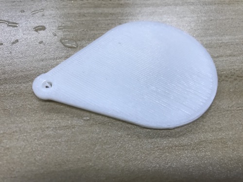
2.3.5 3D print the servo propeller
- Use Fusion360 to draw holes in different diameters
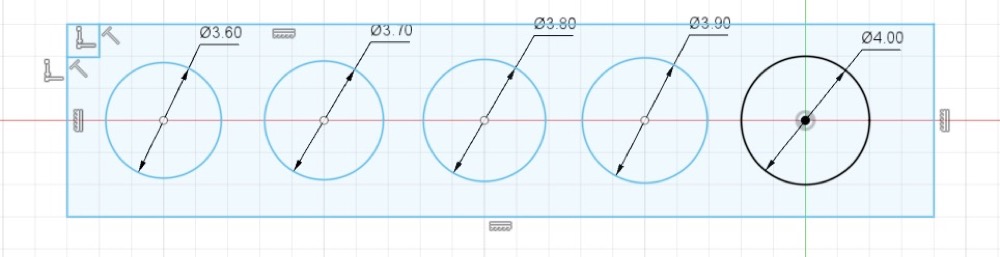
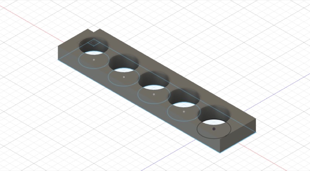
- 3D print and figured the second(3.7mm) fit my servo the best
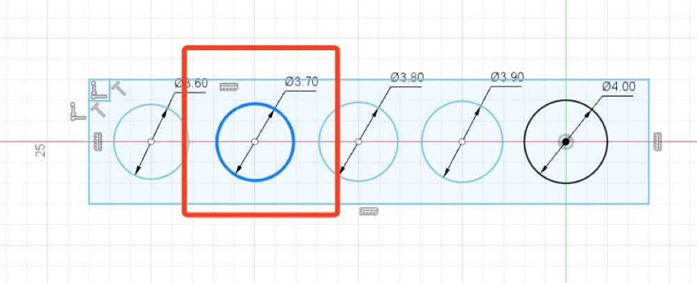
- Design the final propeller and the holding hole diameter 3.7mm
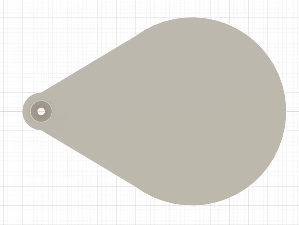
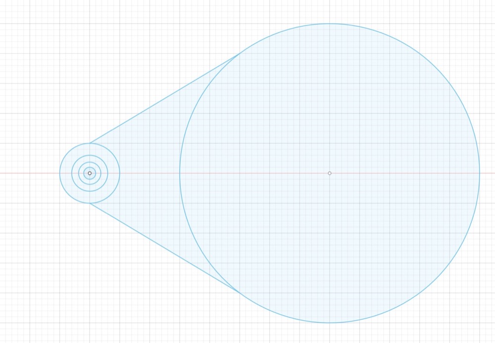
- 3D print the propeller
Showed in the final project video above
2.4 Remote controlled feeder
-
The sensor will be collected to ESP32 board gateway and send through wifi to the router and to a cloud.I will develop a simple application(web based) as a remote control to control my project remotely. And through above controller i will send my command to the cloud and all the way back to my project..
-
I need to do some modification to the original interface.
2.4.1 Modify the ESP32 web interface
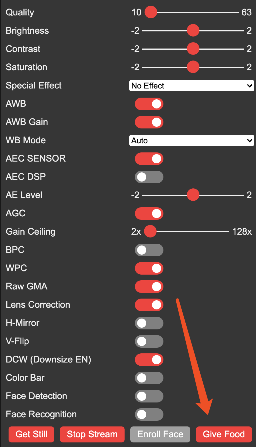
My final modified web interface
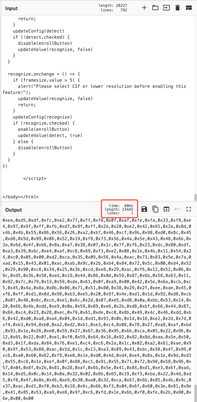
- In the ESP32 server library there is a file named “camera_index.h” - it’s the web interface of the web server. The HTML codes were written in 16 binary codes.
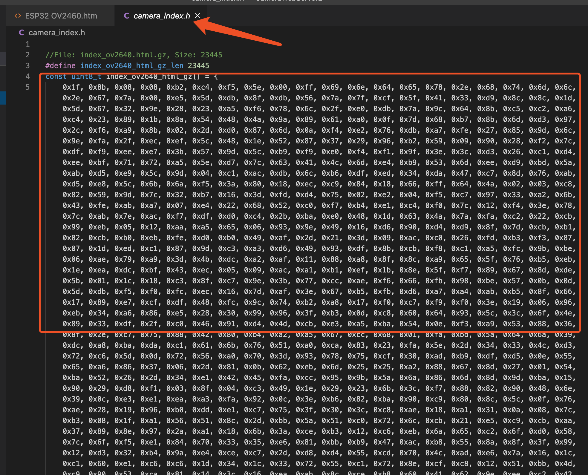
- Use Cyberchef online tool - There is a tutorial explain how to do it - to turn existed binary codes from the library to html code. When modification of the HTML done, translate back the HTML codes into binary and paste them back to the arduino library.
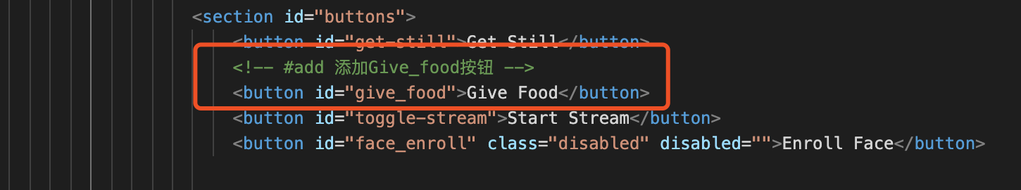
- I added a button ‘Give food’ to the interface by modifying several line of codes
2.4.2 Remote control servo
To make “give food button” interacting with the servo, i modified the Codes. My codes can be downloaded here. Changed that i had made in short as following:
- In the file “app_httpd.cpp”
//#add a 'to_give' bool varible, changes to '1' once received a 'give food'
//#add obtain give_food request from 'give_food'
//#add get whether if need to give food currently
- In the file ‘Cameraserver2.ino’
#include "esp_camera.h"
#include <WiFi.h>

//
// WARNING!!! Make sure that you have either selected ESP32 Wrover Module,
//            or another board which has PSRAM enabled
//

// Select camera model
//#define CAMERA_MODEL_WROVER_KIT
//#define CAMERA_MODEL_ESP_EYE
//#define CAMERA_MODEL_M5STACK_PSRAM
//#define CAMERA_MODEL_M5STACK_WIDE
#define CAMERA_MODEL_AI_THINKER

#include "camera_pins.h"

const char *ssid = "x.factory";
const char *password = "make0314";

void startCameraServer();

//#add from app_httpd.cpp 来自app_httpd.cpp
bool giveFood();

//------ 时间的相关设置
#include "time.h"
const char *ntpServer = "pool.ntp.org";
const long gmtOffset_sec = 28800; //东八区时间
const int daylightOffset_sec = 0;

//---------#add 设置闪光灯引脚为4------------
#define LED_PIN 4

//--------#add 时间检测----------------
bool isCheck = false;
int start_int = 1230;
int start_int2 = 1231;

//--------#add 伺服电机----------------
#include <ESP32Servo.h>
Servo myservo; // create servo object to control a servo
// 16 servo objects can be created on the ESP32
int pos = 0; // variable to store the servo position
// Recommended PWM GPIO pins on the ESP32 include 2,4,12-19,21-23,25-27,32-33
int servoPin = 2;

void printLocalTime()
{
  struct tm timeinfo;
  if (!getLocalTime(&timeinfo))
  {
    Serial.println("Failed to obtain time");
    return;
  }
  Serial.println(&timeinfo, "%A, %B %d %Y %H:%M:%S");
}
//--------#add 获取时间整数----------------
int getTimeInt()
{
  struct tm timeinfo;
  //  int time_int;
  if (!getLocalTime(&timeinfo))
  {
    Serial.println("Failed to obtain time");
    return 0;
  }
  Serial.println(&timeinfo, "%A, %B %d %Y %H:%M:%S");
  int hour_int = timeinfo.tm_hour;
  int min_int = timeinfo.tm_min;
  String time_string = int2String(hour_int) + int2String(min_int);
  int time_int = time_string.toInt();
  Serial.println("time_int: " + String(time_int));
  return time_int;
}
//--------#add 将小于10的整数加0,并变为字符串----------------
String int2String(int the_time_int)
{
  String the_time_string;
  if (the_time_int < 10)
  {
    the_time_string = "0" + String(the_time_int);
  }
  else
  {
    the_time_string = String(the_time_int);
  }
  return the_time_string;
}

void setup()
{
  Serial.begin(115200);
  Serial.setDebugOutput(true);
  Serial.println();

  camera_config_t config;
  config.ledc_channel = LEDC_CHANNEL_0;
  config.ledc_timer = LEDC_TIMER_0;
  config.pin_d0 = Y2_GPIO_NUM;
  config.pin_d1 = Y3_GPIO_NUM;
  config.pin_d2 = Y4_GPIO_NUM;
  config.pin_d3 = Y5_GPIO_NUM;
  config.pin_d4 = Y6_GPIO_NUM;
  config.pin_d5 = Y7_GPIO_NUM;
  config.pin_d6 = Y8_GPIO_NUM;
  config.pin_d7 = Y9_GPIO_NUM;
  config.pin_xclk = XCLK_GPIO_NUM;
  config.pin_pclk = PCLK_GPIO_NUM;
  config.pin_vsync = VSYNC_GPIO_NUM;
  config.pin_href = HREF_GPIO_NUM;
  config.pin_sscb_sda = SIOD_GPIO_NUM;
  config.pin_sscb_scl = SIOC_GPIO_NUM;
  config.pin_pwdn = PWDN_GPIO_NUM;
  config.pin_reset = RESET_GPIO_NUM;
  config.xclk_freq_hz = 20000000;
  config.pixel_format = PIXFORMAT_JPEG;
  //init with high specs to pre-allocate larger buffers
  if (psramFound())
  {
    config.frame_size = FRAMESIZE_UXGA;
    config.jpeg_quality = 10;
    config.fb_count = 2;
  }
  else
  {
    config.frame_size = FRAMESIZE_SVGA;
    config.jpeg_quality = 12;
    config.fb_count = 1;
  }

#if defined(CAMERA_MODEL_ESP_EYE)
  pinMode(13, INPUT_PULLUP);
  pinMode(14, INPUT_PULLUP);
#endif

  // camera init
  esp_err_t err = esp_camera_init(&config);
  if (err != ESP_OK)
  {
    Serial.printf("Camera init failed with error 0x%x", err);
    return;
  }

  sensor_t *s = esp_camera_sensor_get();
  //initial sensors are flipped vertically and colors are a bit saturated
  if (s->id.PID == OV3660_PID)
  {
    s->set_vflip(s, 1);       //flip it back
    s->set_brightness(s, 1);  //up the blightness just a bit
    s->set_saturation(s, -2); //lower the saturation
  }
  //drop down frame size for higher initial frame rate
  s->set_framesize(s, FRAMESIZE_QVGA);

#if defined(CAMERA_MODEL_M5STACK_WIDE)
  s->set_vflip(s, 1);
  s->set_hmirror(s, 1);
#endif

  WiFi.begin(ssid, password);

  while (WiFi.status() != WL_CONNECTED)
  {
    delay(500);
    Serial.print(".");
  }
  Serial.println("");
  Serial.println("WiFi connected");

  startCameraServer();

  Serial.print("Camera Ready! Use 'http://");
  Serial.print(WiFi.localIP());
  Serial.println("' to connect");

  //# add 时间的相关设置
  configTime(gmtOffset_sec, daylightOffset_sec, ntpServer);
  printLocalTime();

  //-------#add 设置闪光灯灯引脚 --------
  pinMode(LED_PIN, OUTPUT);

  //--------#add 伺服电机----------------
  myservo.setPeriodHertz(50);           // standard 50 hz servo
  myservo.attach(servoPin, 1000, 2000); // attaches the servo on pin 18 to the servo object
}

void loop()
{
  // put your main code here, to run repeatedly:

  //  printLocalTime();
  int time_int = getTimeInt();
  //---------根据是否到达时间,进行处理--------
  if (time_int == start_int || time_int == start_int2)
  {
    //---------根据之前是否执行任务,进行处理--------
    if (isCheck)
    {
      Serial.println("has check");
    }
    else
    {
      Serial.println("light on");
      giveFoodNow();
    }
  }
  else
  {
    isCheck = false;
    digitalWrite(LED_PIN, LOW);
    Serial.println("light off");
  }

  bool to_give = giveFood();
  if (to_give)
  {
    Serial.println("light on");
    giveFoodNow();
  }

  delay(1000);
}

void giveFoodNow()
{
  digitalWrite(LED_PIN, HIGH);
  isCheck = true;
  //--------------电机转动----------------v
  for (pos = 0; pos <= 180; pos += 1)
  { // goes from 0 degrees to 180 degrees
    // in steps of 1 degree
    myservo.write(pos); // tell servo to go to position in variable 'pos'
    delay(15);          // waits 15ms for the servo to reach the position
  }
  for (pos = 180; pos >= 0; pos -= 1)
  {                     // goes from 180 degrees to 0 degrees
    myservo.write(pos); // tell servo to go to position in variable 'pos'
    delay(15);          // waits 15ms for the servo to reach the position
  }
  digitalWrite(LED_PIN, LOW);
  //--------------电机转动----------------^
}
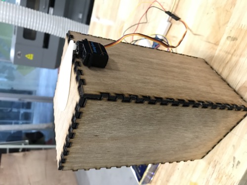
2.5 Assembly
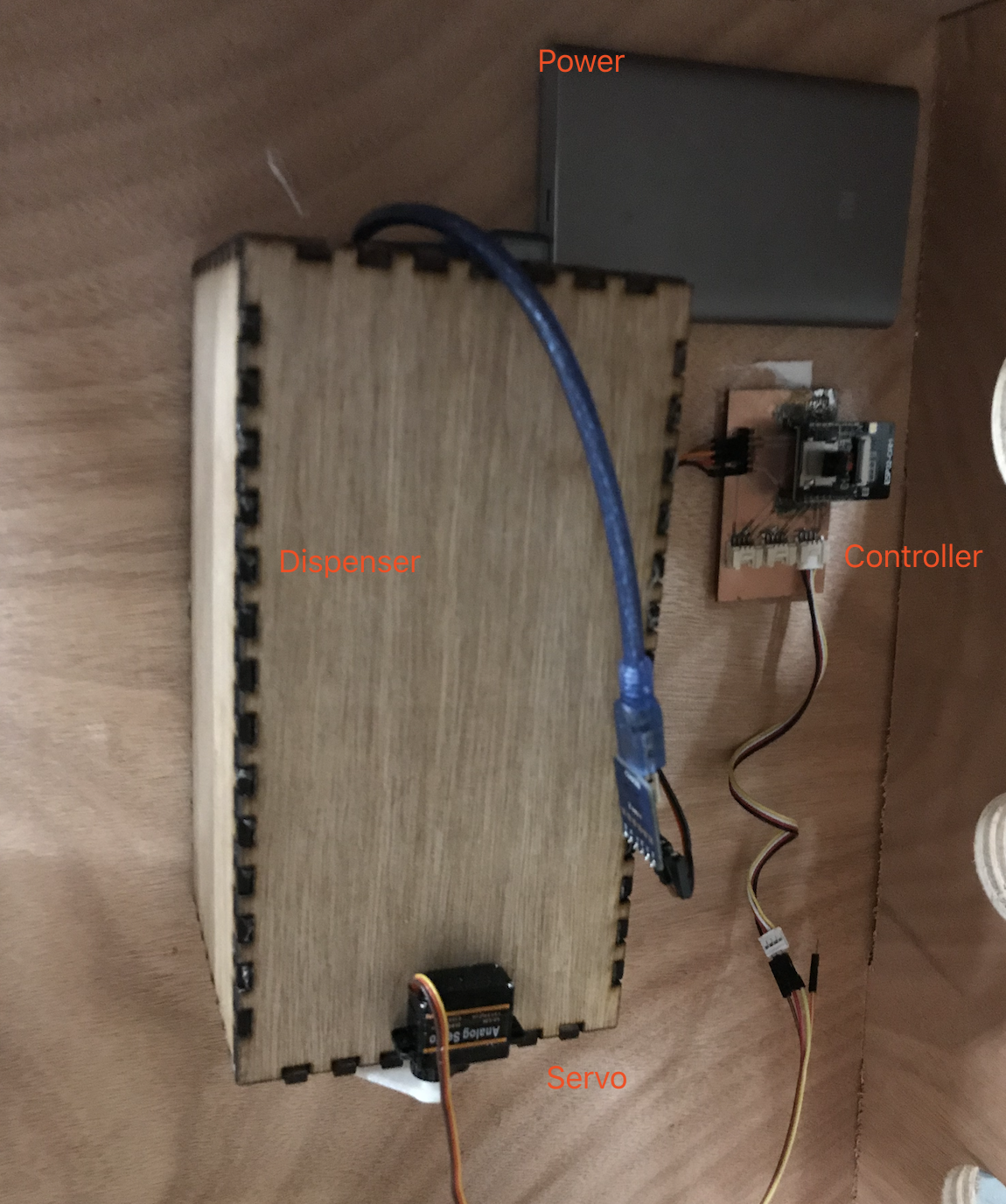
- Use hot melt glue gun to Glue the propeller to the servo and the servo to the dispenser
-
Double-sided tape to the dispensor_box, power bank and ESP32 controller board.
-
Detailed assembling process recorded as below video.
2.6 FinalProject_VideoEditting plan
-
Why i do this project & How i wanted it to be
-
Showing the hero shot, how the project works
-
Structure part
The Smart_Puppy_House (3D design and computer controlled machining)
The dispenser(2D&3D design and Lasercutting)
The propeller(3D design and 3D printing)
- Electronics|embeded programming|input&output Part
ESP32 board(Electronics design and production)
servo(Output)
Automatic control and Remote control(Input and embeded programming)
-
Assembly
-
Final HeroShot and thanks to FabAcademy
3. Evaluate whether my project is successful or not
1) My project is able to feed the dogs in certain time of a day automatically –> YES
2) I can control the motor and monitor my dog remotely through a web based interface. —-> YES
4. My design files
- My dispenser_DXF_File
- My sketches for automatic controlled servo
- My sketches for remote controlled servo