11. Output Devices
1. Assignment && week workflow planning
1.1 Assignment requirements:
-
individual assignment: add an output device to a microcontroller board you’ve designed,and program it to do something
-
group assignment: measure the power consumption of an output device
2. How i did it
2.0 HeroShot of the week
2.1 Measuring the power consumption
Power Supplying to the circuit is 5V.
By using an oscilloscope i got my speaker running at around 3.79V.
By using an multimeter i got my speaker funning at around 300ma.
P = UI = 3.79*0.3 = 1.13watts
2.2 Playing with Grove Beginner Kit
Have done that during week10(input devices week). I played with Buzzer, LED, OLED as output devices
2.3 Interfacing speaker to microcontroller and controlling
- BoM
| Name | Qty |
|---|---|
| Attiny45 | 1 |
| MOSFET | 1 |
| 5v regulator | 1 |
| 02X2 pin header | 2 |
| FTDI header | 1 |
| 10k ohm resistor | 1 |
| 1uF capacitor | 1 |
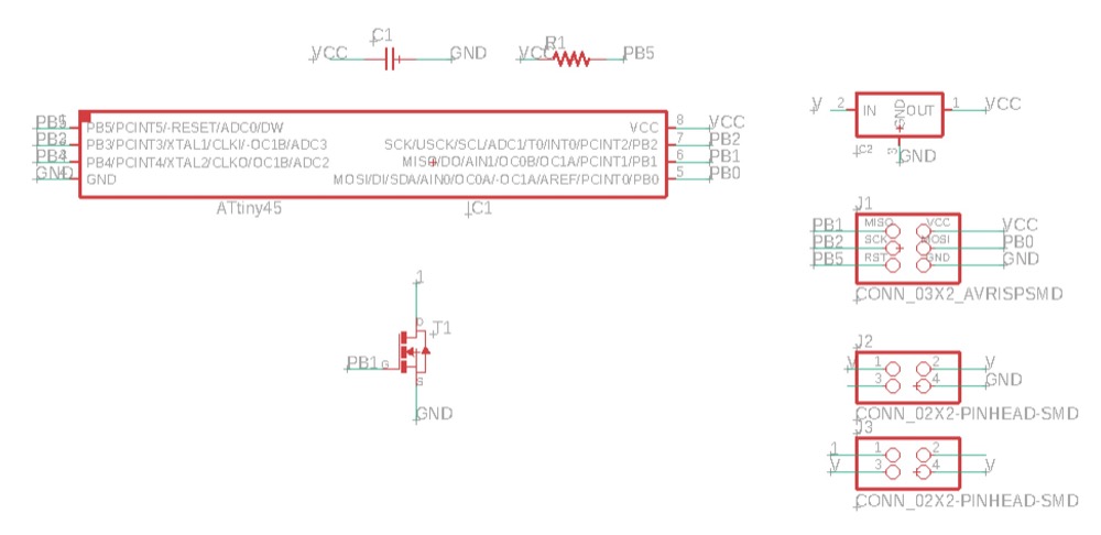
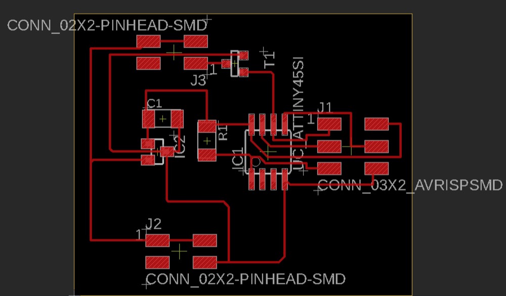
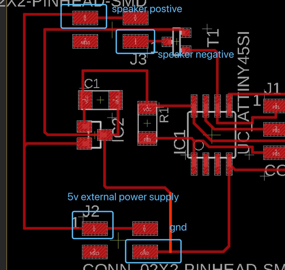
- Draw the schematic && layout
The reference traces can be found from fabacademy_page.
Following is my schematic and layout.
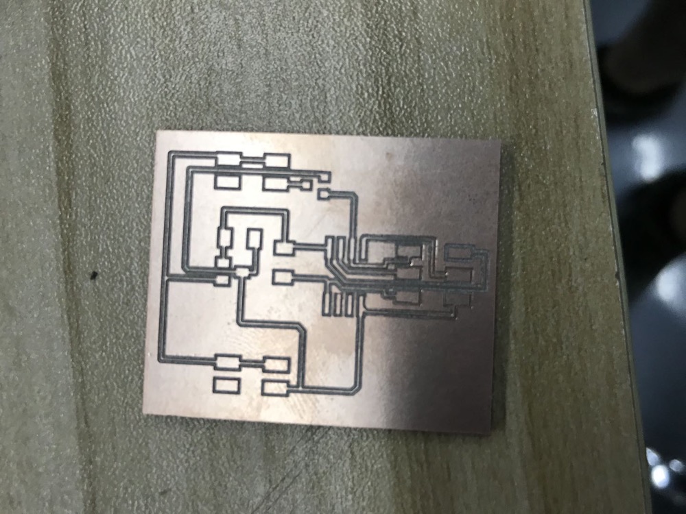
- Mill the board & Stuffing
The progress is documented in my previous assignment - Electronic Production Week.
Here i just show the finished board
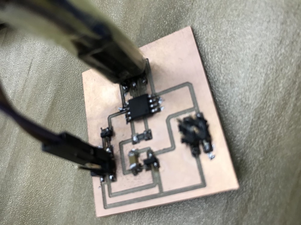
- Make the speaker run
Connected the speaker and added the external power supply this way.(However using the Arduino as power supply worked also quite well)
Used Arduino as ISP(The process i’d described it many times in my previous assignments) - I firstly tried the Arduino example codes “toneMelody” and changed the pin ‘8’ to ‘PB1’. Most of the time it didn’t work. It worked one time and the speaker sounded very weird. After a while of debugging(Tested out the power consumption, short or open circuits, etc.), it finally turned out it was because of the code. The example code ‘tone’ might have a problem with it’s ‘digitalWrite’ function - It didn’t put PB1 to output voltages so that the MOSFET didn’t work appropriately.
I tried the sketch written in C by Neil, it works well.
I also then tried to use with Arduino code. My Arduino code
#define SPEAKER PB1

int BassTab[]={1911,1702,1516,1431,1275,1136,1012};//bass 1~7

void setup()
{
    pinInit();
}
void loop()
{
        /*sound bass 1~7*/
    for(int note_index=0;note_index<7;note_index++)
    {
        sound(note_index);
        delay(500);
    }
}
void pinInit()
{
    pinMode(SPEAKER,OUTPUT);
    digitalWrite(SPEAKER,LOW);
}
void sound(uint8_t note_index)
{
    for(int i=0;i<100;i++)
    {
        digitalWrite(SPEAKER,HIGH);
        delayMicroseconds(BassTab[note_index]);
        digitalWrite(SPEAKER,LOW);
        delayMicroseconds(BassTab[note_index]);
    }
}
3. Problems Occurred & Solutions
3.1 locating Speaker, Power, N, IC2 in Eagle.
N = MOSFET_nT23, IC2 and power are simply connectors. Able to find them all from eagle_fab.lbr.