9. Input Devices
This week, I tried to measure the intensity of the light by using photo sensors. Due to the lockdown for the coronavirus, I can’t use the milling board this time but tried check their operations by a breadboard and Arduino UNO Compatible Board.
Assignments
group assignment:
- Probe an input device’s analog levels and digital signals.
individual assignment:
- Measure something: add a sensor to a microcontroller board that you have designed and read it.
X. Group Assignment
Link to group session page.
X. Individual Assignment
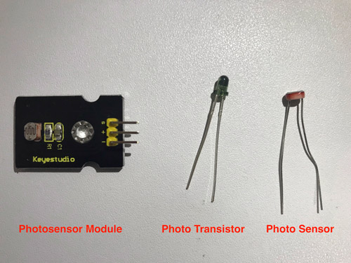
1. Photo Sensor Module
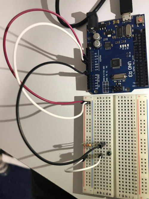
I checked the operation of the photo sensor using the photocell sensor module(PSM) along with this link.
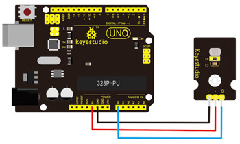
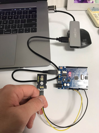
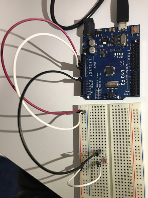
First, connected a PSM to Arduino UNO along with the below diagram. And then connected Arduino to my PC by a USB connector.

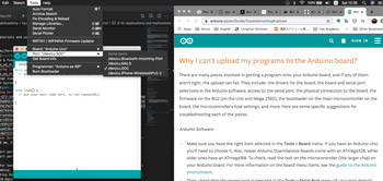
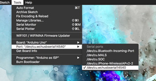
Opened Arduino IDE, and set up the operation environment from Toolbar: Tools -> Board: Arduino UNO, Port: /dev/cu.wchusbserial14540, Programmer: Arduino as ISP.
Failure
Need a driver to be recognized the Arduino’s Port.
My PC couldn’t recognize the Arduino connection port. Yamamoto-san who is one of our support members for the student in Kamakura told me that it needs a driver for Arduino’s USB serial convert IC: CH340G to recognize a port. And Kai Naito who is our instructor told me how to download the driver from here. Installing it, my PC could recognize the Arduino port properly.
I got the sample code from here and uploaded it on Arduino IDE.
Code1 - Light sensor
int sensorPin =A0 ;
int value = 0;
void setup()
{
 Serial.begin(9600); }
void loop()
{
 value = analogRead(sensorPin);

Serial.println(value, DEC);

delay(50);
}
Yeah, I could make it!
2. Constitute Photo Sensor Circuit by Myself
After finished the photosensor module, I realized that its circuit structure is very simple and I can make it. So… I made it.
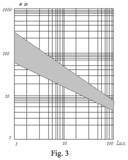
I used CdS cell photosensor: GL5528. Its resistance value changes with the intensity of the ambient light.
Specification
| Spec | Value | Unit |
|---|---|---|
| Peak sensitivity wavelength | 540 | nm |
| Light resistance | 10-20 | KΩ |
| Dark resistance | 1 | MΩ |
*Light resistance is the resistance when the ambient light is applied on the sensor while Dark resistance is one when the ambient light is not applied on it.
Absolute Rating
| Item | Value | Unit |
|---|---|---|
| Max voltage | 150 | V |
| Max power | 100 | V |
Note
How to use a breadboard
You can learn how to use a breadboard from here.
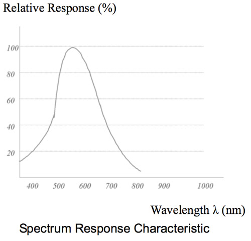
Relative response vs wavelength
Resistance vs illuminance
I could use the same code with the above one.
Okay, Good!
3. Constitute Photo Transistor Circuit by Myself
Next, I tried to use a photo transistor for sensing the light, but very easy to use.
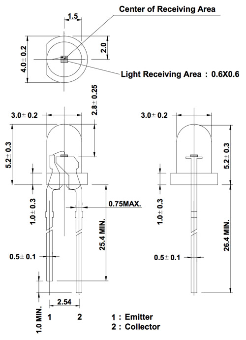
The NJL7502L photo transistor which is made in Japan is used.
Specification
| Spec | Value | Unit |
|---|---|---|
| Peak sensitivity wavelength | 560 | nm |
| Photocurrent | 33 | µA |
Absolute Rating
| Item | Value | Unit |
|---|---|---|
| Collector-emitter voltage | 70 | V |
| Emitter-collector voltage | 10 | V |
| Photocurrent | 10 | mA |
| Wattage | 150 | mW |
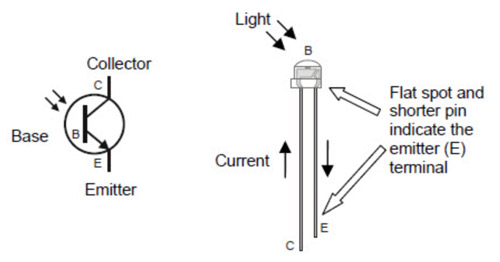
Polarity with phototransistor
Make sure that a photo transistor is connected on the right direction because photo transistor has polarity on the pin connection: Please remember that transistor has Collector, Base, and Emitter terminals(Link).
Relative response vs wavelength
You can see the peak photocurrent value 530 nm on this graph.
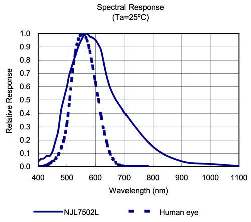
I can use almost the same circuit structure and code with the above.
2020/7/22 Work the photo sensor with the PCB that I made
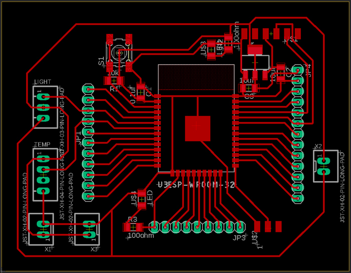
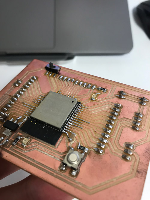
To meet this week’s assignment, I need to make the PCB by myself and read the sensor with it. So I made the PCB with ESP-32 which is the MCU with WiFi and Bluetooth connectivity and tried working the photo sensor with it.
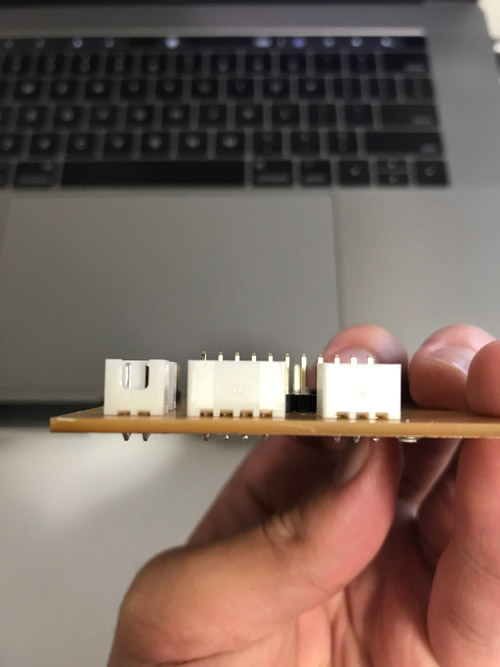
First, here is the PCB with ESP-32 that I made. To add the other sensors like temperature sensor, I added the XH connector and optimized their positions;
| Part | Value | Number |
|---|---|---|
| C1 | 0.1uf | 1 |
| C2, C3 | 10uf | 2 |
| JP1 | PINHD-1X11 | 1 |
| JP3 | PINHD-1X9 | 1 |
| JP4 | PINHD-1X13 | 1 |
| LIGHT | JST-XH-03-PIN-LONG-PAD | 1 |
| R1 | 10kohm | 1 |
| R2, R3 | 100ohm | 2 |
| S1 | 6MM_SWITCH6MM_SWITCH | 1 |
| TEMP | JST-XH-04-PIN-LONG-PAD | 1 |
| U$1 | FTDI-SMD-HEADER | 1 |
| U$2 | SPDTSWITCH | 1 |
| U$3, U$4 | LED | 2 |
| U2 | V_REG_LM1117SOT223 | 1 |
| U3 | ESP-WROOM-32 | 1 |
| X1, X2, X3 | JST-XH-02-PIN-LONG-PAD | 3 |
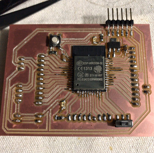
Soldered it.
Tip
Pre-heat on where you’d like to solder
Pin pitch of ESP-32 is very narrow and every copper line also becomes thin. So if I failed to solder pins and then touched the soldering iron tip to the thin copper line again and again to revise it, it would easily peels off.
The important things to solder it at one time is applying heat to where you solder in advance. Low temperature on where you solder occurs that solder are not expanded to the copper line. Solder remains to the soldering iron tip and the solder ball are created. These causes the solder bridge between pins.
By pre-heating the copper line in advance, solder moves to the copper line easily.
Tip
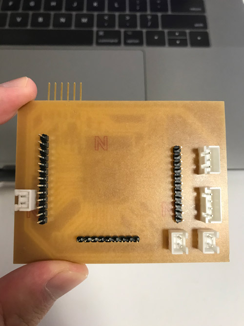
Tips for soldering the parts which has high height
If you’d like to solder the connector perpendicular to the PCB, the good tip is fix them with a tape. In the case of soldering the header pins, fixing pins with the breadboard and then solder PCB with pins is a good way.
For me, all of the connectors I use has the same height. So When I solder them, I passed all the connectors through the PCB’s holes in advance and keep the PCB perpendicular to the surface of the working desk. When you solder the different height of connectors, make sure to solder the smaller one first.
And I revised some points of code 1, especially pin number and serial upload speed. To write a code to ESP-32, please make sure that you set IO0 pin to the ground by the slide switch or something and set the EN pin to the ground temporally by push the button while uploading the code. And then you can run the code on ESP-32 if you open IO0 pin by using the slide switch and again set EN pin to the ground temporally.
These process is shown in the below video.
Code2 - Light sensor_2
int sensorPin =34;
int value = 0;

void setup()
{
 Serial.begin(115200);
}
void loop()
{
 value = analogRead(sensorPin);

Serial.println(value, DEC);

delay(1000);
}
Done!!
X. Conclusions
Submission
Self-reviews
1. This week’s work
This week, I’d like to try more lots of sensors like Sound sensor, Color sensor, Temperature sensor but actually, I can’t afford to do that because all the schedule that I planed has to be changed due to the lockdown for the coronavirus. I’m planning the new schedule again and again when the situation has changed but EVERY plan has been broken… Thant’s very very irritate me. I don’t have such many times…
But it was very fun for me to sense something using sensor and I found out that trying to make circuit board by bread board is relatively easy. So I’d like to try them someday.
Learning from a maker member
Finishing the half time of Fab Academy, I realized that there are so many things to learn from not only things that I made but also people like students and instructor.
2. Project Management
Score (Max: 100)
-
Hierarchy: 0
I was not thinking about it at all… -
Triage: None
-
Spiral Development: 100
-
Supply-side Time Management: 100
-
Parallel Development: None
I was not thinking that I use input device like sensor to my final project… -
Document as you work: 100
MEMO
What I wanted to learn more
-
Other sensors
Especially, sound sensor, color sensor, and CO2 sensor. I wanted to interact my generative arts with the sound.
I wanted to make handy color sensing modules that is driven by battery to use when I make my artwork.
I wanted to make a CO2 monitor module for sensing the air condition in my house. -
How each sensor works
I graduated the material science and engineering in college so I’m very interested how things work and their mechanisms.