11. Output devices
This week I try driving DC geared motor, DC motor pump, and Stepper motor. I plan to use DC motor pump and stepper motor for my final project.
Assignments
group assignment:
- Measure the power consumption of an output device.
individual assignment:
- Add an output device to a microcontroller board you’ve designed, and program it to do something
X. Group Assignment
Link to group session page.
X. Individual Assignment
I checked that the DC geared motor works with a motor driver module to learn the basics of how the motor works with a microcontroller. And then, I operated DC motor pump and stepper motor with a motor driver: A4953 motor driver that I plan to use in my final project and the basic Arduino IDE programming. All three motors worked with Arduino UNO.
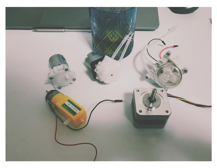
Materials
-
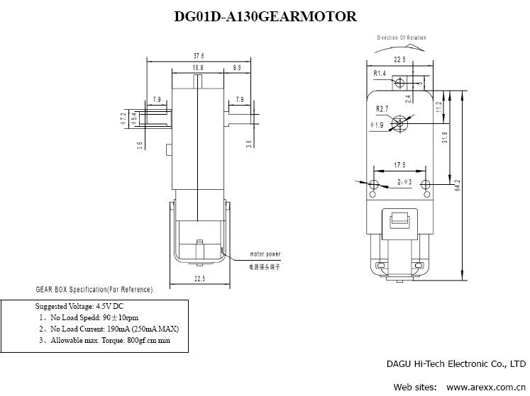
DC geared motor: Hobby Gear motor -> Datasheet
-
DC motor pump: Acogedor 6V DC Dosing pump
-
Stepper motor: 42SHD4002-24B -> Datasheet
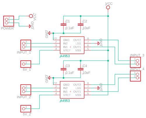
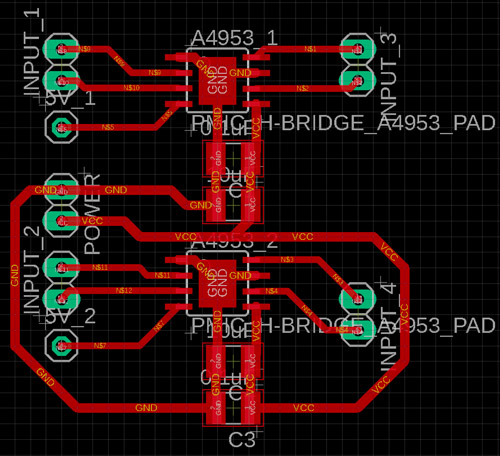
1. Motor Driver Module Drawn by Eagle
For my final project (FP), I made motor driver modules (MDM) this week. I plan to use the 3 pcs modules for FP (for two stepper motors and one DC motor pump). But, due to the lockdown with COVID-19, I couldn’t go to the lab and mill the MDM. So this week, I used the class kit which was provided by Fablab Kamakura. And I’m going to make and use MDM for my final project. Please check it out from the following link.
BoM
- Motor Driver: A4953 x 2
- Capacitor: 0.1uF x 2
- Capacitor: 10uF x 2
- Pin: (1 x 2) x 5
- Pin: (1 x 1) x 2
2020/10/11 Test of the motor driver module
I made a motor driver module (MDM) and incorporated it into my final project.
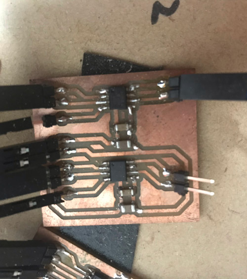
The integrated PCBs is below. It looks too complex. But it’s easy to work the MDM.
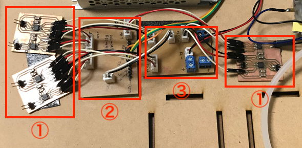
① Motor driver module
② Main Board (with microcontroller)
③ Power Supply Module (can supply 5V and 12V)
*You can show the detail about the PCB integration in my final project page.
The voltage 12 V are applyed to Vcc of the motor driver and Pin Vref are pulled up with 5V. And input pins are connected with the digital or analog pins of the main board (maybe microcontroller), and output pins are connected with DC motor pump.
To confirm the work of the MDM and DC motor pump, I wrote the code to drive the motor with changing its behavior by inputting the keyword to the serial monitor.
As I push “S” on the keyboard, DC motor pump start driving forward and flow the ink. As I push “B”, DC motor pump start driving backward. As I push “C”, DC motor pump stop to drive.
const int DriverA_1 = A0;
const int DriverA_2 = A1;
//const int DriverB_1 = 10;
//const int DriverB_2 = 11;
char key;
char S = 's';
char B = 'b';
char C = 'c';

void setup() {
  pinMode(DriverA_1, OUTPUT);
  pinMode(DriverA_2, OUTPUT);
  //pinMode(DriverB_1, OUTPUT);
  //pinMode(DriverB_2, OUTPUT);
  Serial.begin(9600);
}

void loop() {
  if (Serial.available()) {
    key = Serial.read();
    if(key == S){
      Serial.print("Start!");
      Serial.println("");
      motor(HIGH, LOW, 3000);

    } else if (key == B){
      Serial.print("Back!");
      Serial.println("");
      motor(LOW, HIGH, 3000);

    } else if (key == C){
      Serial.print("Stop!");
      Serial.println("");
      motor(LOW, LOW, 3000);

    }
  }
}

void motor(int a1, int a2, int d){
  digitalWrite(DriverA_1, a1);
  digitalWrite(DriverA_2, a2);
  //digitalWrite(DriverB_1, a1);
  //digitalWrite(DriverB_2, a2);
  delay(d);
}
2. DC geared motor, DC motor pump
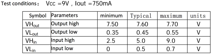
I used the L91105 to drive DC geared motor and DC motor pump. FIrstly, I checked the datasheets of motors and driver to see if the motor driver can drive those motors properly.
Vcc is the supply voltage for driving a thing. According to the datasheet L91105’s Vcc is 6 V at typical (2〜12V at min. and max.) which can be driven by Arduino 5V pin.
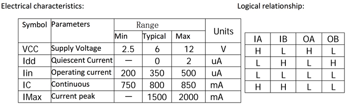
Next, I checked the logical relationship of the motor driver.
No worry, very simple. When IA (IB) was written to HIGH (LOW), OA (OB) becomes HIGH (LOW).
This modules can drive 2 motors at once. So I tried driving 2 motors.
So I wrote the programming with Arduino language as below.
Code1 - Motor Rotation
const int DriverA_1 = 6;
const int DriverA_2 = 7;
const int DriverB_1 = 8;
const int DriverB_2 = 9;

void setup() {
  pinMode(DriverA_1, OUTPUT);
  pinMode(DriverA_2, OUTPUT);
  pinMode(DriverB_1, OUTPUT);
  pinMode(DriverB_2, OUTPUT);

}

void loop() {
  motor( HIGH,  LOW, 3000);
}

void motor(int a1, int a2, int d){
  digitalWrite(DriverA_1, a1);
  digitalWrite(DriverA_2, a2);
  digitalWrite(DriverB_1, a1);
  digitalWrite(DriverB_2, a2);
  delay(d);

}
I made it!! But I noticed that I didn’t write the code that stops the operation of motors in the program. So once the program is written in Arduino IDE, the motor can’t stop its operation.
To solve this problem, I tried adding the code that if I push key ‘s’, the motor start driving and if I push key ‘c’, the motor stops.
Code2 - Interaction with serial communication
const int DriverA_1 = 6;
const int DriverA_2 = 7;
const int DriverB_1 = 8;
const int DriverB_2 = 9;
char key;
char S = 's';
char C = 'c';

void setup() {
  pinMode(DriverA_1, OUTPUT);
  pinMode(DriverA_2, OUTPUT);
  pinMode(DriverB_1, OUTPUT);
  pinMode(DriverB_2, OUTPUT);
  Serial.begin(115200);
}

void loop() {
  if (Serial.available()) {
    key = Serial.read();
    if(key == S){
      Serial.print("Start!");
      Serial.println("");
      motor(HIGH, LOW, 3000);

    } else if(key == C){
      Serial.print("Stop!");
      Serial.println("");
      motor(LOW, LOW, 3000);

    }
  }
}

void motor(int a1, int a2, int d){
  digitalWrite(DriverA_1, a1);
  digitalWrite(DriverA_2, a2);
  digitalWrite(DriverB_1, a1);
  digitalWrite(DriverB_2, a2);
  delay(d);
}
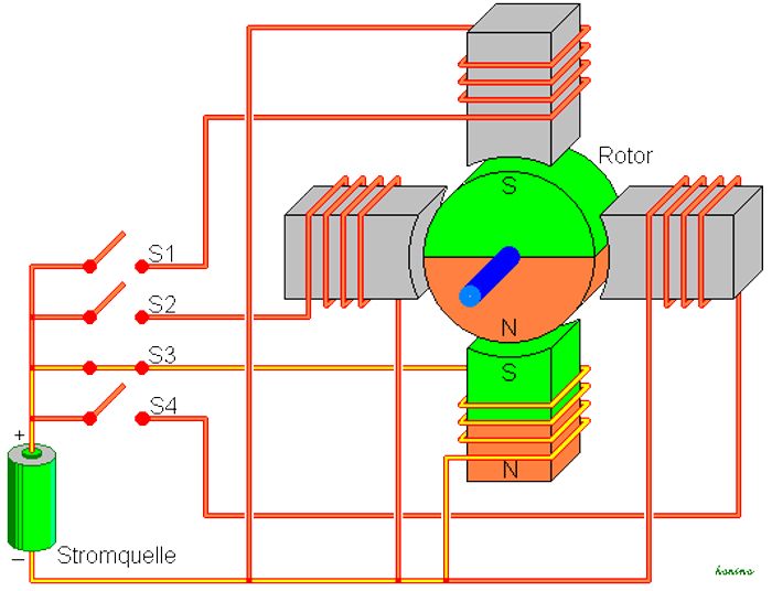
3. Stepper motor
I used a stepper motor driven at 12V so I have to change the motor driver. I chose A4953 driver IC to drive a stepper motor.
To drive a stepper motor, two A4953 is needed because A4953 has only 2 output pins whereas 4 output pins from drivers is needed for controlling one bipolar stepper motor.
Below image explains how the stepper motor works.
The code is below;
Code3 - Control stepper motor
void setup() {
    pinMode(8,OUTPUT);
    pinMode(9,OUTPUT);
    pinMode(10,OUTPUT);
    pinMode(11,OUTPUT);
    #define RED 8
    #define GREEN 9
    #define BLUE 10
    #define WHITE 11
}

void loop() {
    digitalWrite(GREEN,HIGH);
    digitalWrite(RED,LOW);
    delay(1);
    digitalWrite(WHITE,HIGH);
    digitalWrite(BLUE,LOW);
    delay(1);
    digitalWrite(GREEN,LOW);
    digitalWrite(RED,HIGH);
    delay(1);
    digitalWrite(WHITE,LOW);
    digitalWrite(BLUE,HIGH);
    delay(1);

}
I did it! Good!
X. Conclusions
Submission
Self-reviews
1. Power of open source
I didn’t know how the DC motors and stepper motor works properly for the first time. But I researched the source and I found the source code that how I works the stepper motors.
2. Project Management
Score (Max: 100)
-
Hierarchy: 100
I planed to do from DC geared motor pump, DC motor pump, and Stepper motor. -
Triage: None
-
Spiral Development: 100
This week I made the motor driver module for my final project. -
Supply-side Time Management: 20
I’ve not thought it very much… -
Parallel Development: 100
For my final project, I tried to read the CoreXY code, make a driver module in parallel. -
Document as you work: 50
I was so engrossed in the work to drive motor that I forgot to take a document…
MEMO
None