4. Computer controlled cutting
Assignment
- group assignment:
- characterize your lasercutter’s focus, power, speed, rate,
- kerf, and joint clearance
- individual assignment:
- cut something on the vinylcutter
- design, lasercut, and document a parametric construction kit, accounting for the lasercutter kerf which can be assembled in multiple ways and for extra credit include elements that aren’t flat
Group assignment
Material
We use 3mm lightwood for this week’s test. First we use calipers to check the thickness.

Focus
The lasercutter has a auto focus function using a ruler. First we insert the ruler into the right place shown on the picture below. Then we push the auto focus function button. The machine will raise the platform until the material touch the end of the roler and push it a little higher. Because there is a sensor inside the machine and the ruler has a hole to cooperate the sensor. When the ruler is higher and the hole is not at the same position when it isn’t pushed up, the machine will recording the height as the focus position. Then the focus is completed.


Software and Driver
We use Inkscape to process all the test files. Some are .DXF , some are .PDF,some are .SVG etc. All of them can be process by Inkscape then print. Here is the print setting interface.

Setting test(power, speed, rate)
We have made two test. One is at the same power and different speed. Another is at the same speed and different power to see the outcome of cutting. Here is the test original files

Same power different speed:

| power | speed | PPI | outcome |
|---|---|---|---|
| 60 | 4.0 | 500 | cut through |
| 60 | 4.5 | 500 | cut through |
| 60 | 5.0 | 500 | a litte through |
| 60 | 6.0 | 500 | not through |
| 60 | 7.0 | 500 | not through |
| 60 | 8.0 | 500 | not through |
| 60 | 9.0 | 500 | not through |
| 60 | 10.0 | 500 | not through |
Same speed different power:

| power | speed | PPI | outcome |
|---|---|---|---|
| 65 | 4.0 | 500 | cut through |
| 60 | 4.0 | 500 | cut through |
| 55 | 4.0 | 500 | cut through |
| 50 | 4.0 | 500 | cut through |
| 45 | 4.0 | 500 | a little through |
| 40 | 4.0 | 500 | not through |
| 35 | 4.0 | 500 | not through |
| 30 | 4.0 | 500 | not through |
Kerf test
We use this test original files to make the kerf test with setting value below(we olny test four colors):
| power | speed | PPI | color |
|---|---|---|---|
| 65 | 4.0 | 500 | black |
| 60 | 4.5 | 500 | red |
| 55 | 5.0 | 500 | green |
| 50 | 5.5 | 500 | yellow |

We use 10 parts in a line for cutting. After the cutting is finished there will be 11 gaps betwwen each of the parts which is very small and difficult to be seen and to be measured. But if you move all the parts into one side, the gap will become big enough to be measured. As you can see the the slower the speed is, the more material is burned. Which means the kerf value is bigger. We use the gap value divide by 11 to get the kerf value.

Joint clearance test
Material thickness:3mm
Setting value: power 60, speed 4.0, PPI 500
We use this test original files.


In this setting value, the kerf is about (3-2.75)/2=0.175mm.
Kerf bend test
Material thickness:3mm
Setting value: power 60, speed 4.0, PPI 500
We use this test original files.


We test them one by one for bending. The result is:

Individal assignment
Laser cutting machine parameters
Power: How strongly the laser fires. A high power will cut through stronger, thicker material, but may end up burning thinner, more flammable stock. A low power may not be strong enough to get all the way through the material. During rastering, higher power will burn more layers off of the material, creating a darker image.
Speed: How fast the head of the laser cutter moves along its gantry. A high speed will cut faster, but may not cut all the way through if you have thicker or stronger materials. A low speed will definitely cut through, but has the potential to burn or melt the edges of the material as it slowly cuts. During raster operations, the laser moves back and forth very quickly, so a high speed on a large piece may wear out the gantry.
Frequency(only for cutting): Determines how fast the laser pulses during a cutting operation. The laser turns on and off rapidly when it makes cuts, so a higher frequency will create a cleaner cut, but if the material is flammable it may end up catching fire, so a lower frequency would be preferable.
Resolution(only for rastering): Determines the resolution and quality of the raster operation. A higher resolution will produce a better, darker image, but if there is too much heat concentrated in one area, it may severely melt, burn, or damage the work piece.
Software
- 2D Design:
- Adobe Illustrator: Powerful graphic design software used to create high quality designs
- AutoCAD: Great drawing software, primarily used by engineers and architects to create detailed drawings and product representations
- Inkscape:Free, open source graphic design software
- 3D Dsign:
- Solidworks:Engineering 3D design software with multiple packages for aiding in design for specific applications
- Autodesk Fusion: Cloud-based CAD platform used to help designers through the entire designing, engineering and manufacturing processes
Vector (most for cutting)
During a cutting operation, the cutting head fires a continuous laser at the material to slice through it. In order to know where to cut, the laser cutter driver reads all of the vector paths in the designed piece. Once you send your file to a laser cutter, only lines that register as only hairline or vector graphics with the smallest possible line thickness will be cut by the laser. All other graphics, like any images or thicker lines, will be rastered, which I’ll explain in a bit. The laser, when supplied with the right settings, will cut all the way through your material, so vector cutting is normally used for cutting out the outline of the part as well as any features or holes that you want to cut out of the material.

Raster (for engraving)
Rastering is a lot different than vector cutting; instead of cutting all the way through the workpiece, the laser will burn off the top layer of the material you are cutting to create two color (and sometimes grayscale) images using the raster effect. In order to raster materials, the laser will usually be set to a lower power than it would when vector cutting material, and instead of shooting down a pulsing beam, it creates fine dots at a selected DPI (dots per inch) so that the laser doesn’t really cut all the way through. The DPI directly correlates to the image resolution and affects how fine an image appears, exactly like image resolution on a computer. By adjusting the DPI you can control the laser’s effect on the material. Rastering on some materials comes out really clearly, while you may not get exactly what you expected on other materials. Before you raster for the first time, make sure you experiment with the settings until you get the desired effect!

What have I tried
Construction kit_1
Under the guidance of Saverio, after studying Joint, I tried to draw a basic model using Solidworks. Then I converted the plane of each part individually into DXF format and imported it into AutoCAD for futher processing. I used the “offset” command to create an offset effect with a length of 0.1mm in each interface part (assuming kerf is 0.2mm). Then I readjusted the line, adjusted the number of parts, re-arranged, and finally completed the first version of the flat graphics.


After the design, I started to fabricate with the machine following the group assignment setting. Then I got the tiny pieces of the kits:
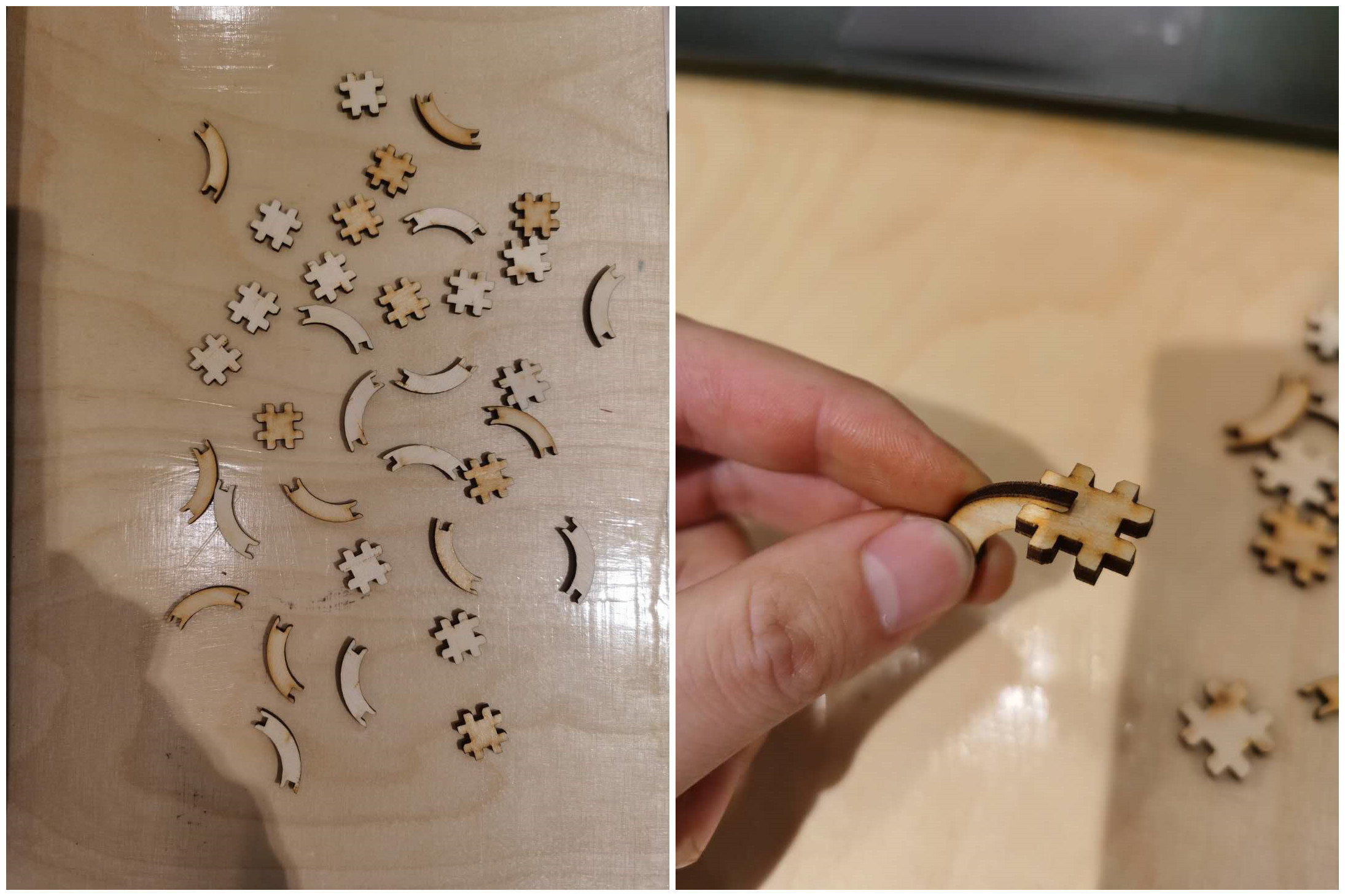
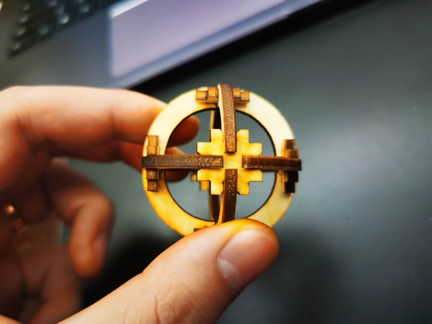
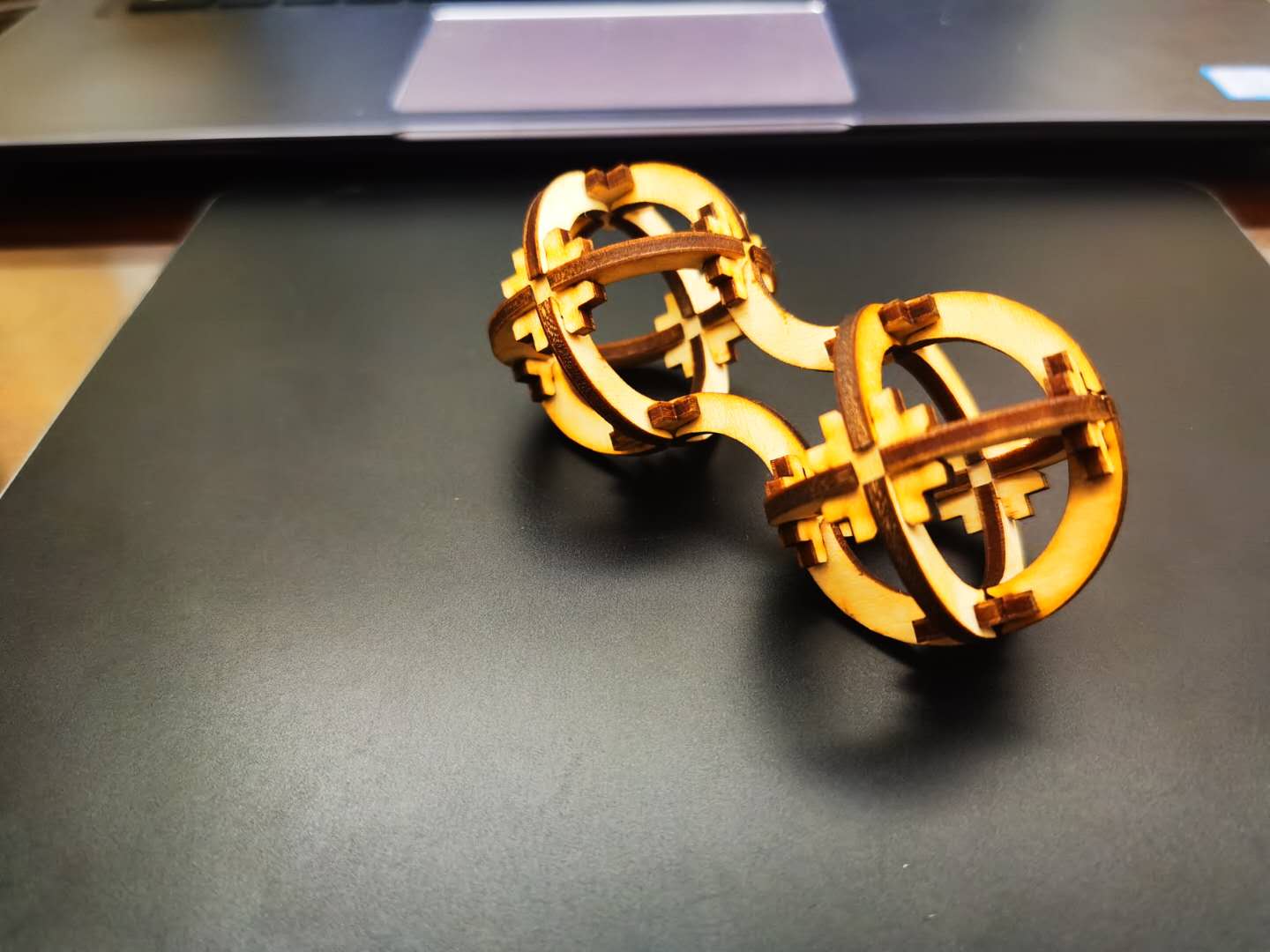
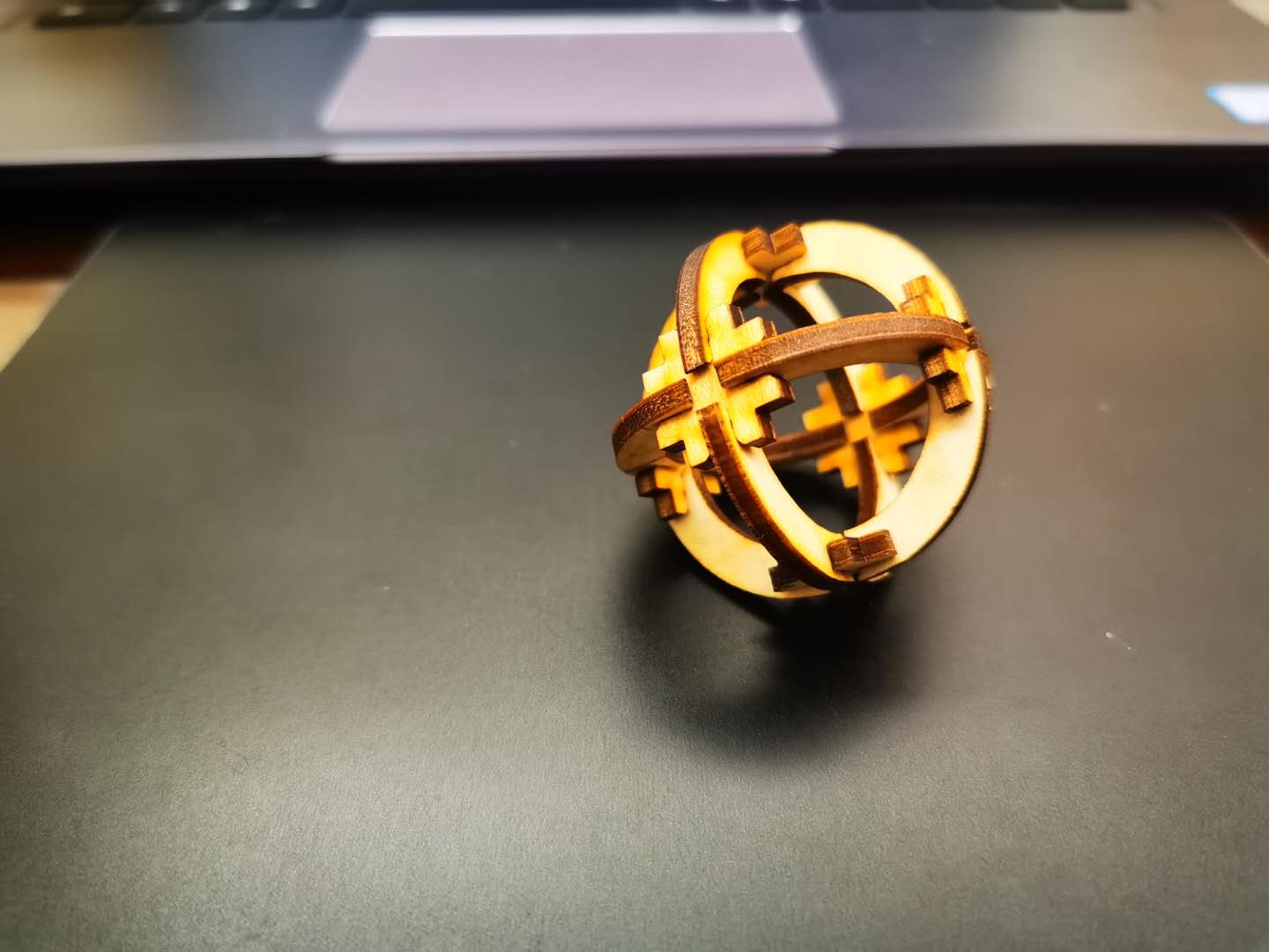
The join is very moderate, which means the kerf setting is right. These two pieces can be combined into a lot of different shapes.
 |
 |
 |
 |
Parametric design
The method of modifying kerf with offset every time is very troublesome and error-prone. So I started experimenting with parameters to adjust the model. I tried to draw a square box using finger as a joint. This is pretty basic. But I used Solidworks to parameterize each joint. As you can see, when I modify the parameters in the table, the entire box, including the interface size, will change accordingly. This is very convenient. And I can use the vernier caliper to measure the actual kerf value and adjust the parameters to make the drawing more accurate.


Construction kit_2
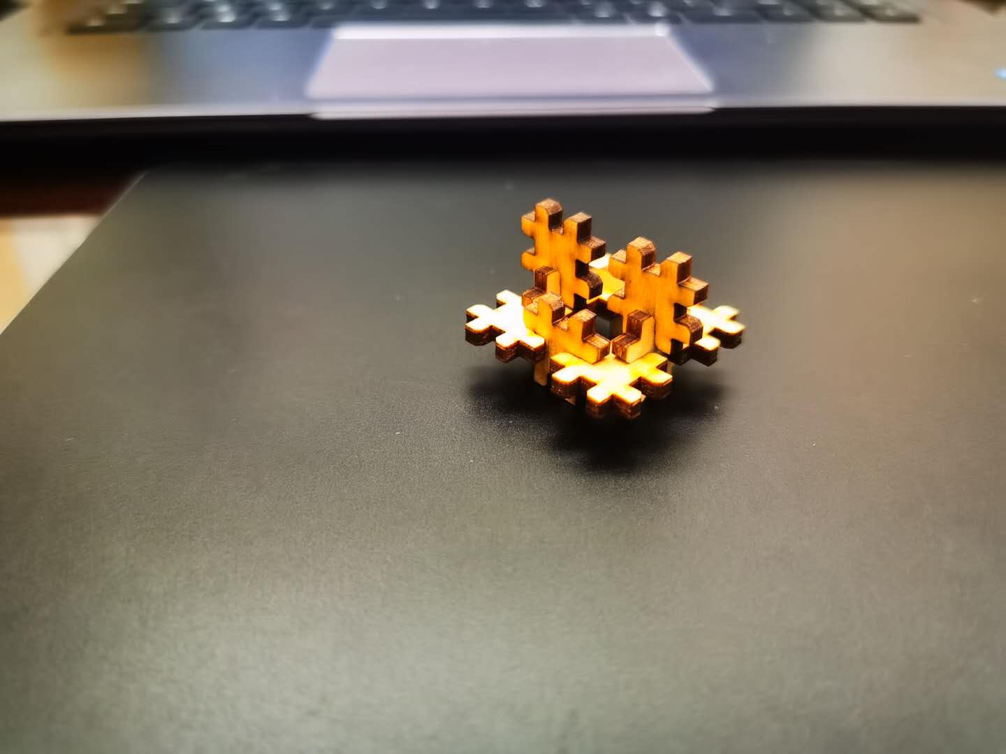
For my final project I have tried a hexagon shape structure which is made by only two different pieces but with a lot of diversity.
Fabrication process:
Outcomes:


Now I can ues it as a prototype of my final project to do the coming test.
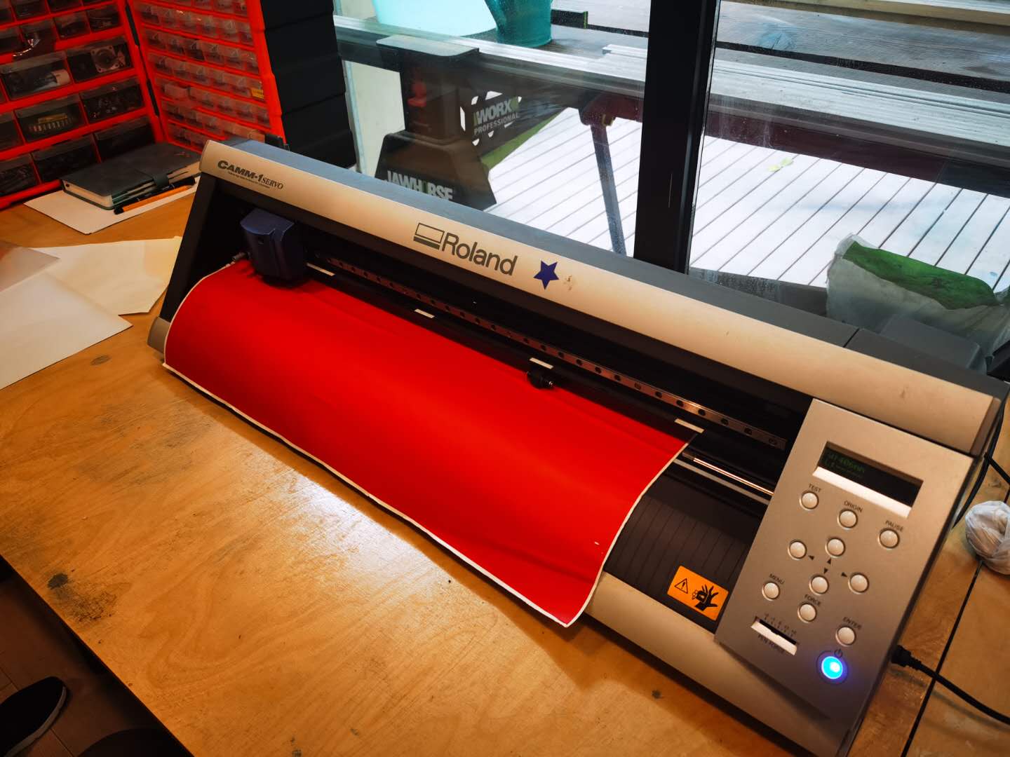
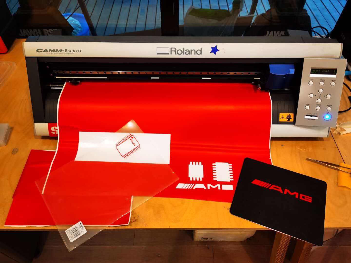
The Vinyl Cutter
I tried the Roland GX-24 vinyl cutter. It is very easy to use and can do a lot of interseting project.
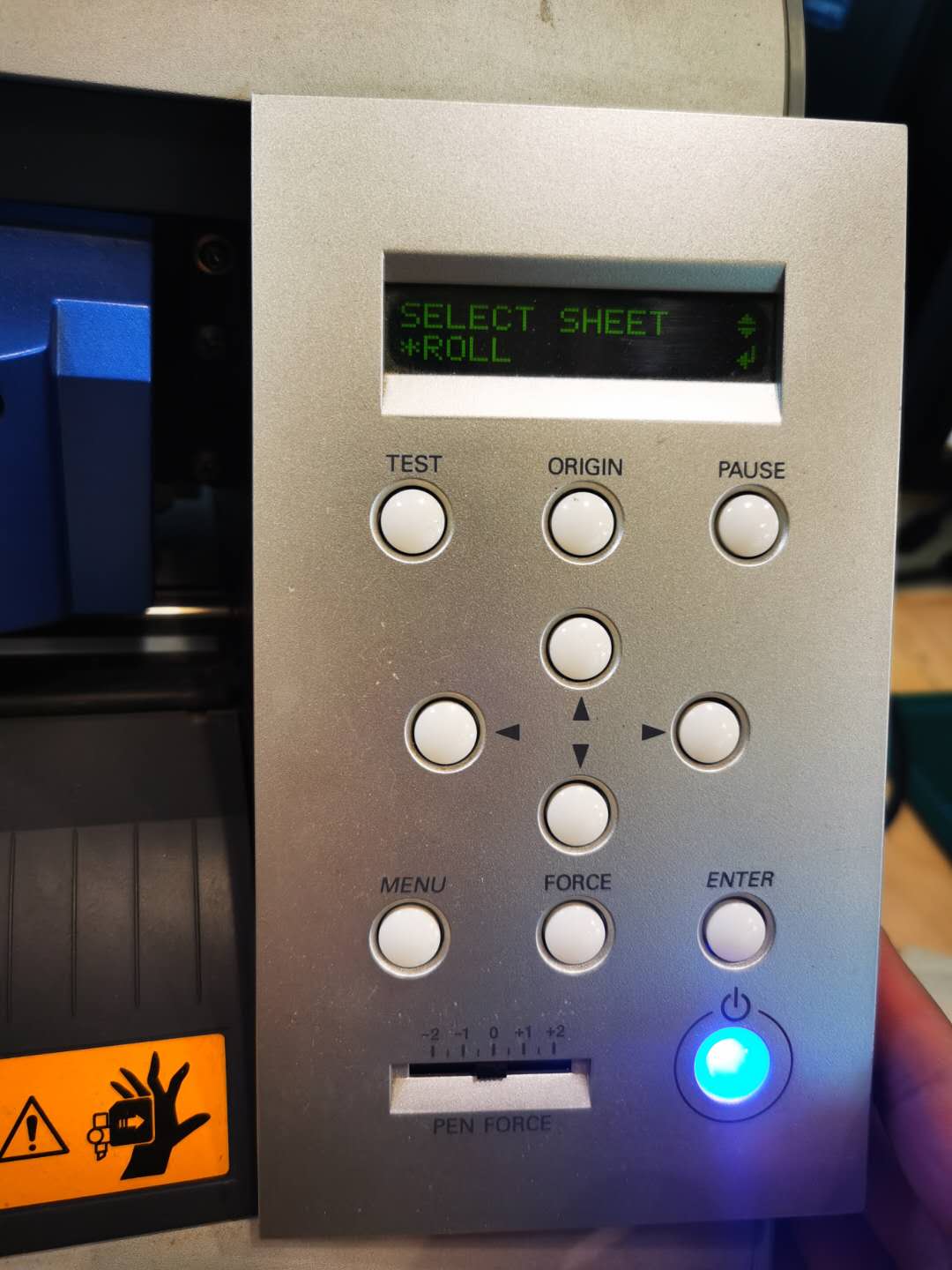
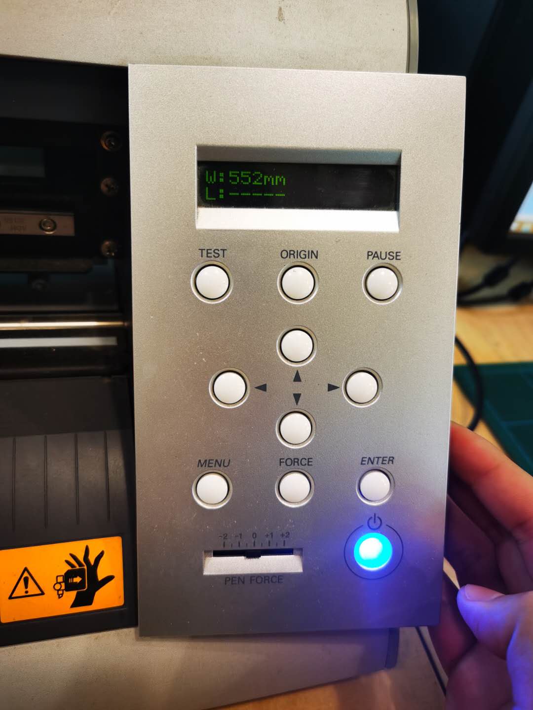
Setting job:
| Origin setting | Sheet setting |
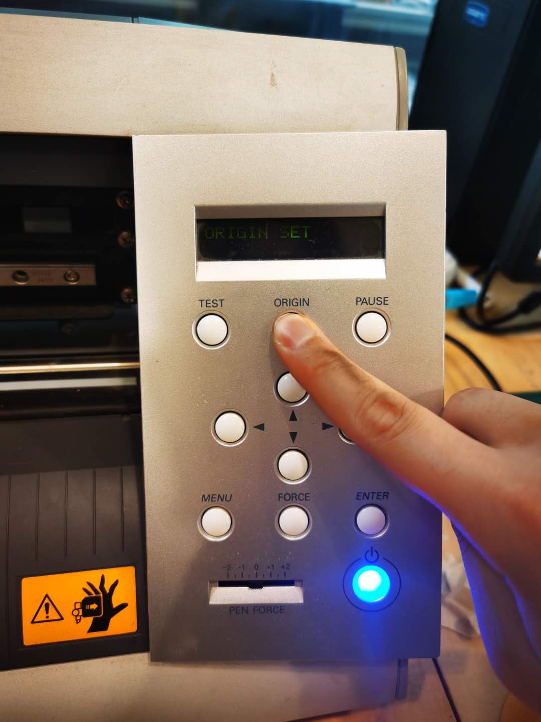 |
 |
| Size setting | Force setting |
 |
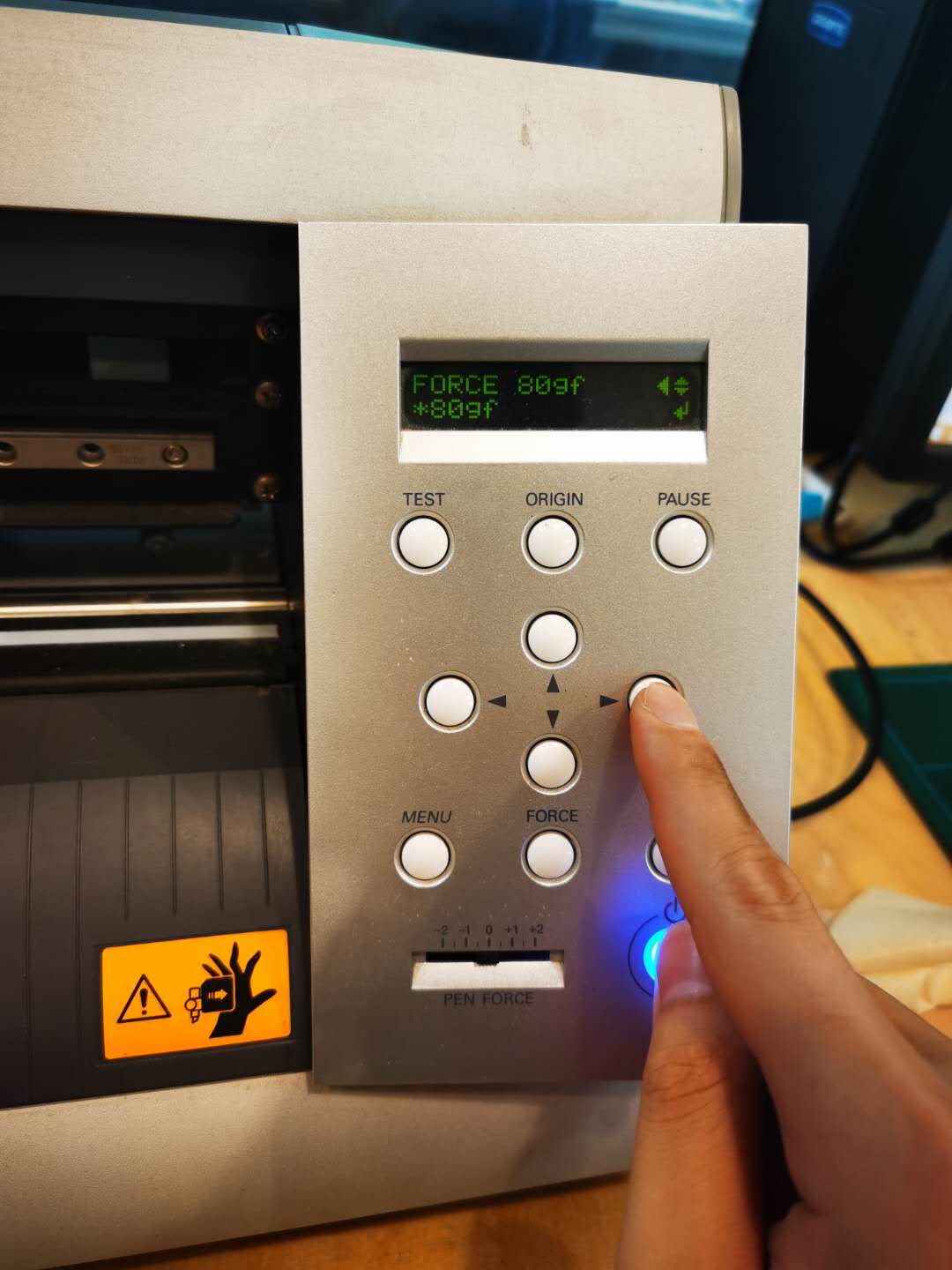 |
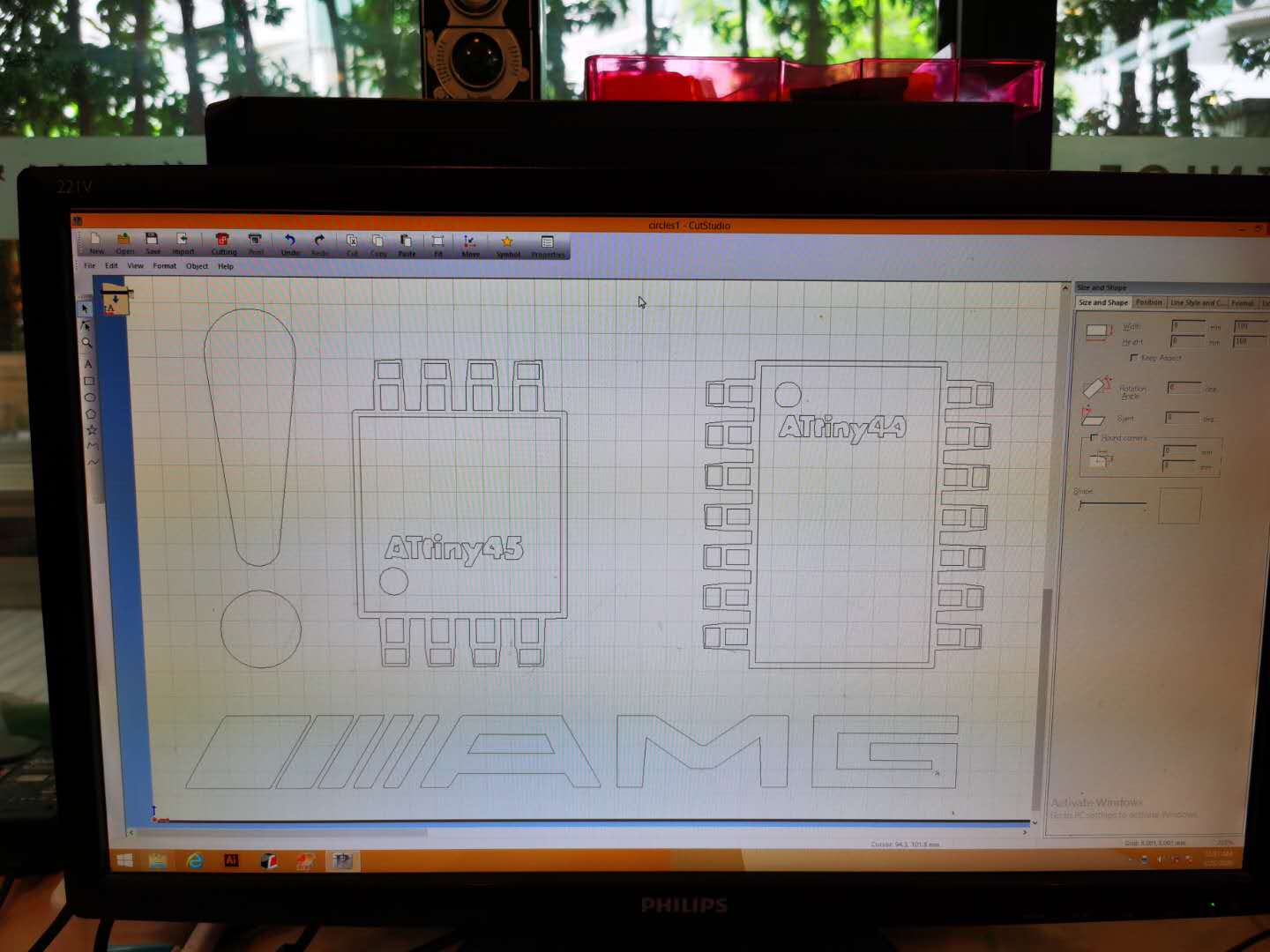
Then use the sorftware to process images that I want to cut:
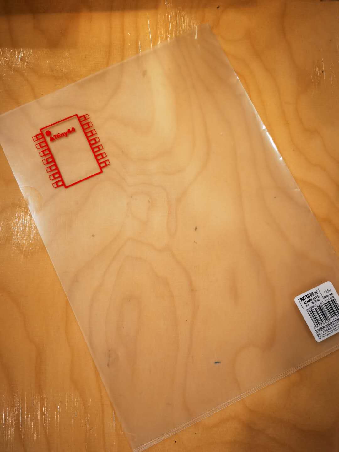
After uploading the G-code to the machine then I move on to the next step: transmitting the object onto the material surface that I want. I used the adhesive tape to put on the pattern then remove it from the roll to my mouse pad.


More object outcomes:
After reading the introduction of the related website of vinyl cutter, I found the introduction of the use of Roland GX-24 on youtube. I found that the utilization rate of vinyl cutter is not as high as that of laser cutter, because only one color can be processed. . If you want to print colored stickers, you have to print the vinyl with another printer, and then let the GX-24 find the position and cut it through 4 points positioning. So I found another product, BN-20, also produced by Roland. It has the functions of a printer and cutter. Next I made a thermal transfer project using BN-20. I imported the photos of my wife and me into the BN-20’s drive, then printed my photos on the vinyl and finished cutting automaticlly. Next, I used transfer adhesive to place the picture on a blank canvas bag, and placed it under the press for about 30 seconds to attach the picture to the canvas bag. The effect is very good, just made a Valentine’s Day gift for my wife.


Useful Link
There two websites which are quite convenient for making a lasercut box:
MakerCase - Simple custom case maker
Boxes.py - Bazillion custom box scripts
These websites are for 2D design refference:
Free SVG Image Gallery
Topographical World Map by Prime8
Jigsaw Puzzle Maker by Draratech