4. Input and Output devices
Input device
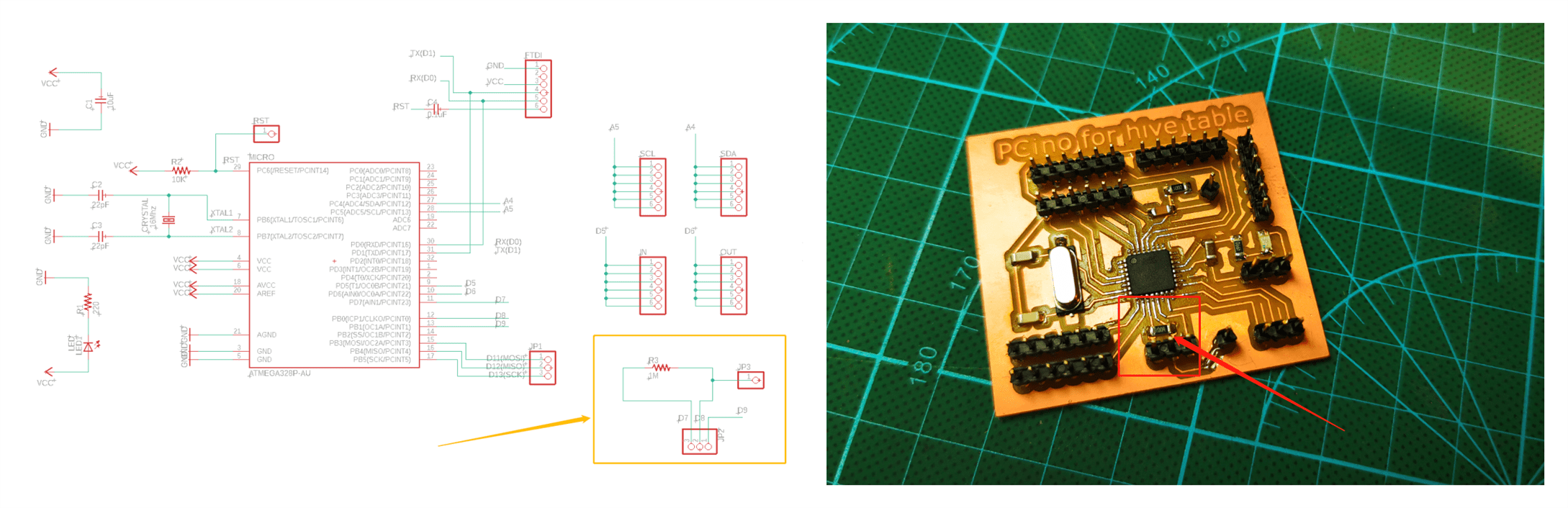
I desided to use the CapacitiveSensor as input because is very simple and has a lot of fun. It is different from the pressure sensor, you don’t have to push the surface to trigger the sensor. All you have to do is to touch the surface.

The bigger the resistor is the more sensitive it will be. To make the circuit more easily to connect I desided to make the resistor onto my final PCB between two pins and set its value as 10MΩ.
Code:
#include <CapacitiveSensor.h>
#define threshold 120  /change the value by testing

#define LED 9
int flag;

CapacitiveSensor   cs_7_8 = CapacitiveSensor(7,8);

void setup() {
  pinMode(LED, OUTPUT);
  Serial.begin(9600);
}

void loop() {
    long total3 =  cs_7_8.capacitiveSensor(30);
    Serial.println(total3);
    if (total3 > threshold) {
      if(flag == 0){
        flag = 1;
        digitalWrite(LED, HIGH);
      }
      else{
        flag = 0;
        digitalWrite(LED, LOW);
      }
      delay(500);
    }
}
I used the single LED instead of the NeoPixels for this test to make the system more clear. I can just change some lines instead of the LED into NeoPixels.
Output device
The output device is NeoPixels. I directually use the Adafruit’s labray to test the NeoPixels. Open Arduino IDE…sample…Adafruit NeoPixels…strandtest and change the pin number into D9 according to the board for my final project, and the counts of NeoPixels into 23(that is for one module round).
Then the LEDs showed a beautifule rainbow to me:
![]()
For the Neopixels need a lot of current, I equiped a powersupply board for them. Looks they works very well.
For my final Project I don’t need so many colors. I can just simple set the into one colore and change them when ever I want.
// all 23 NeoPixels for one strip turn on
 for(int i = 0;i<NUMPIXELS;i++){
      pixels.setPixelColor(i, pixels.Color(0, 0, 150));   /Blue color
          }
      pixels.show();
  delay(1000);
// all 23 NeoPixels for one strip turn off
 for(int i = 0;i<NUMPIXELS;i++){
      pixels.setPixelColor(i, pixels.Color(0, 0, 0));
          }
      pixels.show();
  delay(1000);
Comprehensive test
To be honest, the macgnect combine is so unreliable. Sometimes it is so easily to confuse me about where the problem is when bug appears. So I made a simple prototype to test the Input and Output function.
The Input is a conductive material, connected with 3 1MΩ resistors. The Output is still NeoPixels but just with 4 LEDs. And the power is all 5V.
I made 3 test for the 3 function for my design:
* Single touch control
This function is independent whether the module is separated or combined. With simple touch can turn On/Off them.
- Light domino
Thanks to the extra In/Out pin connected to each side’s magnets. I can realize this amazing effect. Although I have the I2C communication protocals. It is very hard to deside which module is next to the very module that I triggerd. The traditional light domino effect is through photoresistors. But, obviously I can’t place photoresistors on each side of the hexagon otherwise there will be 6 photoresistors in one module. But imagine that if one is triggered, as the same time it turns on the Neopixles, it send a HIGH signal through its OUTPUT pin and the others modules connect to it will receive that signal by its own INPUT pin, and then lignt up itself, sending another HIGH signal…then, one by one chain on/chain off…It will be so beautiful.


- Interface conrtol(I will dwell on it to Interface and application)
After all the test is passed successfully. Then I put them back and connected all the cables and packaging them:
