5. Interface and application
How to use:

Although I have the I2C communication protocals. Each module will has its own adress as slavers, of course, there will also be one master module to receive the signals from interface software or app… process them…then send commands to the slavers.
But, there is a problem: On each side of the hexagon has I2C port (SDA,SCL) to communicate with the others. It’s very hard to determine which side the modules are connected. Is it on the top or bottom? Left or right? No idead… This will result in difficulty to control them by interface. Because you don’t know where the module is.
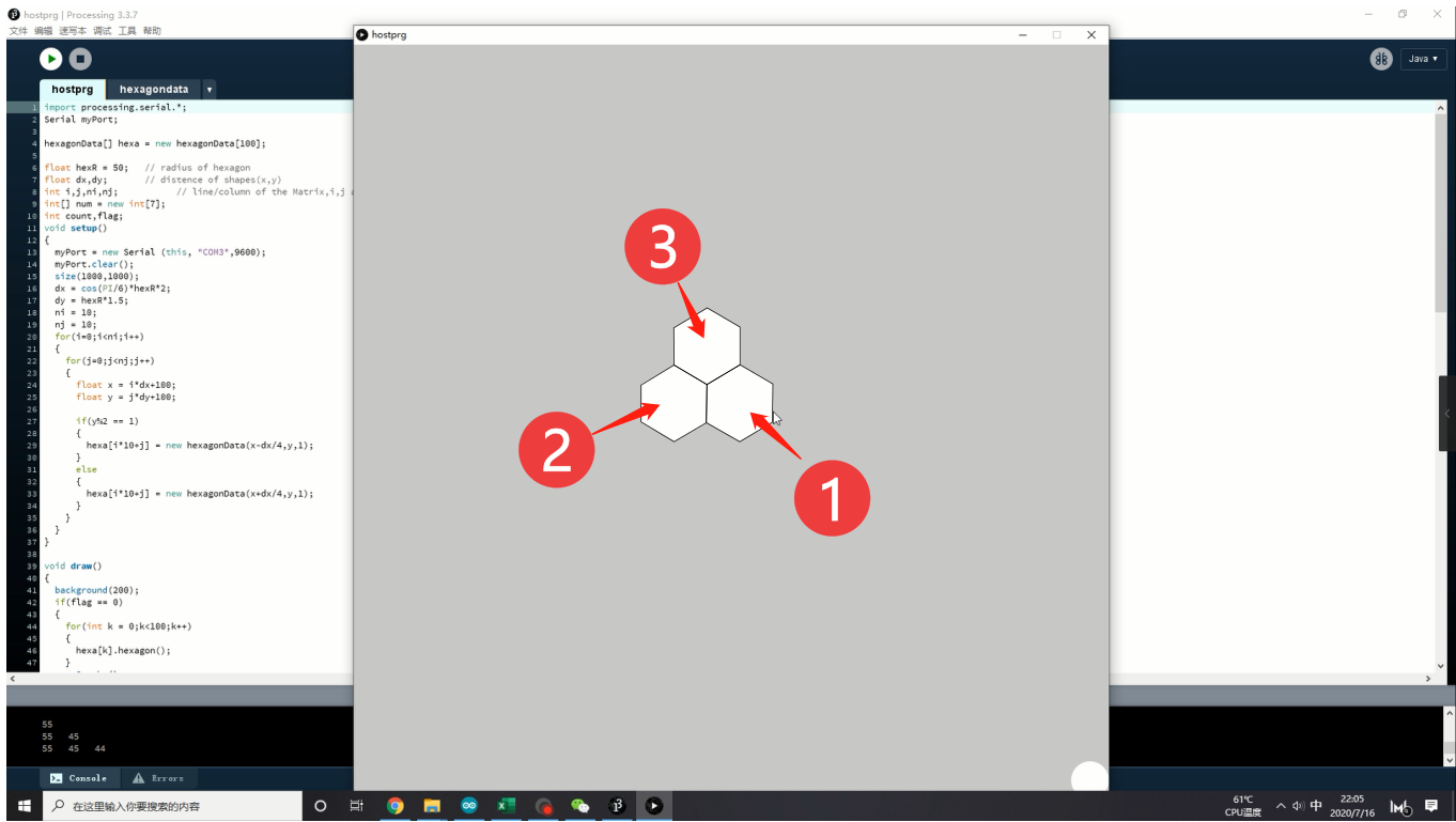
So I decide to make an initialize function. So that the user can define the control panel which has the same shape as you placed. Everytime you combine one module next to last one. You click the corresponding hexagon on the interface. Then, after all the modules are at there place, click “ok” button to turn into control panel.
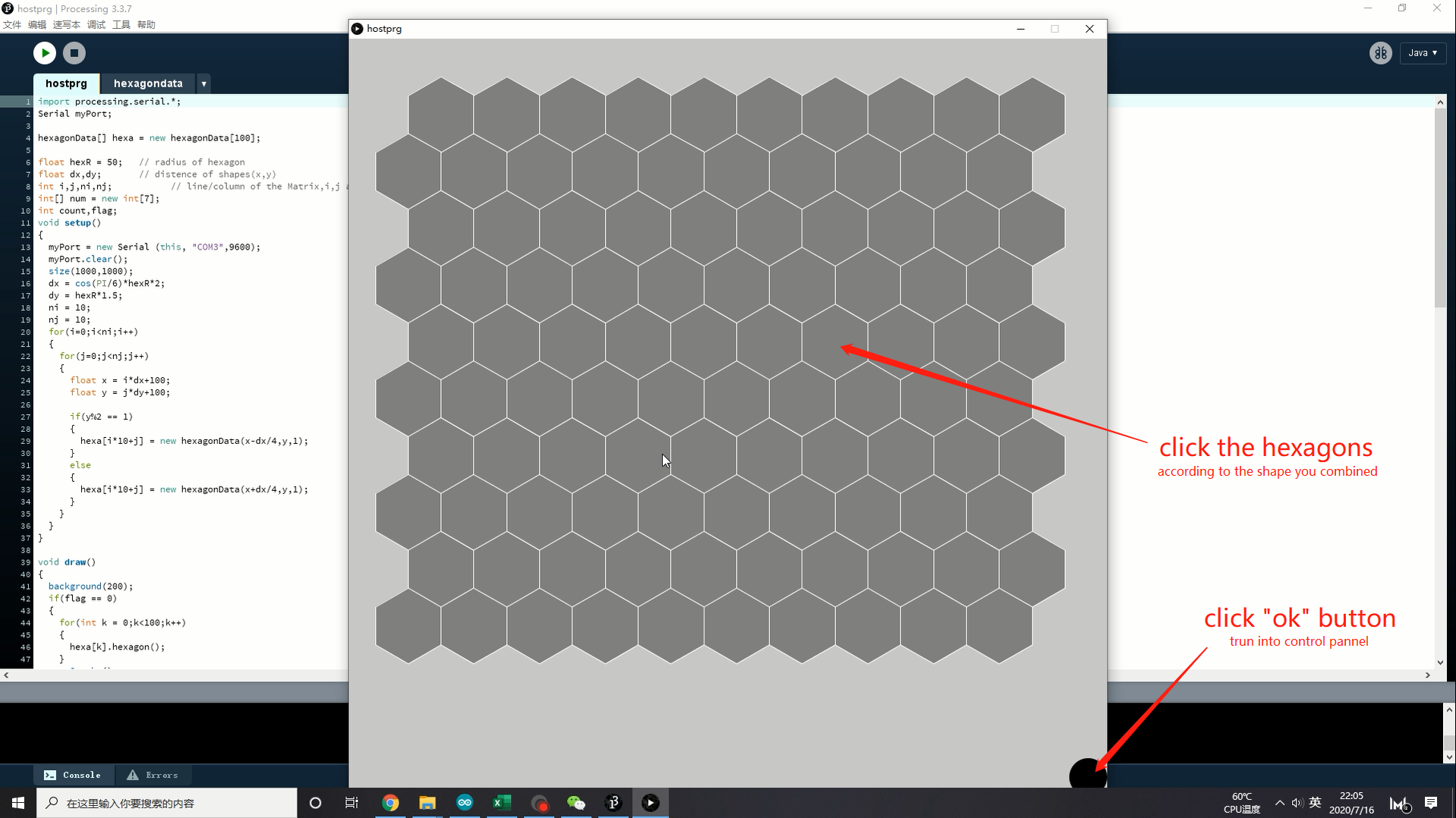
After that the user can just click the hexagon shaped area to turn On/Off the corresponding module by serial port.
Demonstration
Programming
The code will be saperated into three part: The master MCU, the slave MCU, and interface software.
Processing part
I have documented about this part on week15.Networking and Communications. The processing will send signal like: <#adress,state>
Master module
The master MCU’s role is to process the signal <#adress,state> from Processing through the serial monitor, then separate it into two part:
Part 1:
Wire.beginTransmission(i); // transmit to device #i
i is the #adress to deside which slaver will receive the next command.
Part 2:
Wire.write(value); // sends one byte
The slaver will control its module to light Up/Out follow the state.
Code:
#include <Wire.h>
String command = "";
bool newCommandAvailble = false;

void setup() {
  command.reserve(200);
  Wire.begin(); // join i2c bus (address optional for master)
  Serial.begin(9600);
}

void serialEvent() {
  while (Serial.available()) {
    char inChar = (char)Serial.read();
    command += inChar;
    if (inChar == '\n') {
      newCommandAvailble = true;
    }
  }
}

void loop() {
  if (newCommandAvailble) {
    Serial.println(command);
    int i = command.substring(0, 1).toInt();
    int value = command.substring(2).toInt();
  command = "";
  newCommandAvailble = false;

  Wire.beginTransmission(i); // transmit to device #i
  Wire.write(value);              // sends one byte
  Wire.endTransmission();    // stop transmitting

  Serial.print("adress is: ");
  Serial.println(i);
  Serial.print("state is: ");
  Serial.println(value);
  }
}
Slaver modules
The slaver’s role is quite simple. Listen if the master is calling it by #adress, then follow the state command to control its module.
#include <Wire.h>
#include <Adafruit_NeoPixel.h>
#define PIN            9
#define NUMPIXELS      21

Adafruit_NeoPixel pixels = Adafruit_NeoPixel(NUMPIXELS, PIN, NEO_GRB + NEO_KHZ800);

int x;

void setup() {
  Wire.begin(0);                // join i2c bus with address #0
  Wire.onReceive(receiveEvent); // register event

  pixels.begin(); // This initializes the NeoPixel library.
  Serial.begin(9600);           // start serial for output
  Serial.println("Start");
}

void receiveEvent(){
  x = Wire.read();
  Serial.println(x);

}

void loop() {
 if (x == 1 ) {
    turnOn();
      }
  else{
    turnOff();
      }
  delay(500);
}

void turnOn(){
   for(int i = 0;i<NUMPIXELS;i++){
      pixels.setPixelColor(i, pixels.Color(0, 150, 0));
          }
      pixels.show();
}

void turnOff(){
  for(int i = 0;i<NUMPIXELS;i++){
      pixels.setPixelColor(i, pixels.Color(0, 0, 0));
          }
      pixels.show();
}
The next spiral
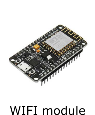
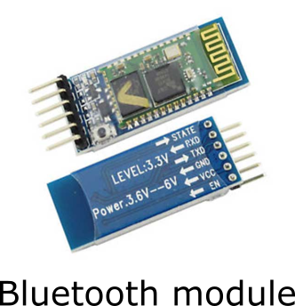
Until now I always use the USB cable to communicate with modules and computer. It is quite unconvenient. So the next spiral is to improve the experience of using to make it wireless by WIFI or Bluetooth.
Files
Arduino_Master.ino
Arduino_Slaver.ino
Processing_hexagondata.pde(a class for hostprg)
Processing_hostprg.pde