19. Project Development
Descrption:
The desktop adopts a modular design concept. The connection between each module is the same (the same mechanical structure and the same communication protocol), so it can be freely combined in shape. The surface of the table consists of many hexagonal modules. Each hexagonal module is identical in shape. Each table is equipped with a cltroller hexagon module and several combination hexagon modules.
When you want a rectangular shape table, you can use 9 or more modules to make it. When you want a round shape table, you only need 7 pieces. All you need to do is split and assemble the modules according to the shape you want. There is a matching slot between each module, which can not only ensure the structural rigidity of the table surface, but also can easily connect the cables required for electronic components. After the table surface is spliced, there is a bayonet under each hexagonal module that can fix the support. You can install the table support under any hexagonal module, as long as the table can be held firmly. And each support can also be adjusted up and down.
Each hexagonal combination module is equipped with: LED strips (RGB) and touch sensors. Each hexagonal control module is equipped with: MCU; LED strip; NeoPixels;
what tasks have been completed, and what tasks remain?
- [√] 2D & 3D DESIGN
- [√] Fabrication processes
- [√] PCB fabrication
- [√] Embeded programming
- [√] Interface and communication
- [ ] System integration and packaging
- [ ] Presentation sild and video
what has worked? what hasn’t?
- [√] Structure part(design, fabrication and assembling)
- [√] The electronic part of PCBs and input/output devices
- [√] The embeded programming of single module test
- [√] The interface of processing
- [ ] Communication of magnets(unstable, sometimes work sometimes not)
what questions need to be resolved?
- Is the size suitable or not?
- Is the designed structural strength strong enough?
- How to make the design more beautiful?
- How to make the communication of magnets more stable?
- Whether its embedded program is rich enough as a game table?
- How to do secondary development of supporting app?
what will happen when?
- Documenting the whole process of the final-project development everyday.
- Structural details optimization will be done by this weekend.
- The electronic part has been finished and the test of them has passed, so the system integration and packaging should be done as soon as possible. Plan to have it done before next Wednesday.
- Trying to use other ways for communication(if Time permits).
- After all the task is done. It will be the time to make slide and video of final-presentation. And I planed to use 1 or 2 days(up to 3 days), Befor the presentation day by mid-July.
what have you learned?
First of all, I have learned how to concentrate wholeheartedly on the project at hand, which will allow me to work very efficiently.
Knowing how to use various digital fabrication equipments, and will reasonably choose the most efficient and suitable equipment to help me complete the project.
Time management. Clear goals and deadlines.
Stress management. This greatly helped me to self-motivate and persevere, helping me complete difficult challenges.
Demand-side & Supply-side time management. Not all materials can be found in the lab immediately. So I have to know how to get them, when, how much? In the same time try to thinking about the alternative materials.
Knowing how to find the answers to the questions. And first of it, ask the right question.
Self-awareness about our own capabilities. knowing that what is the strengths and weaknesses of myself.
Sketchs and concepts
Inspiration photos:
Here is some hexagon shape LED devices:
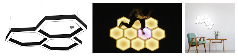
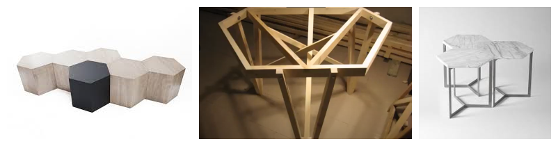
Here is some hexagon shape table:
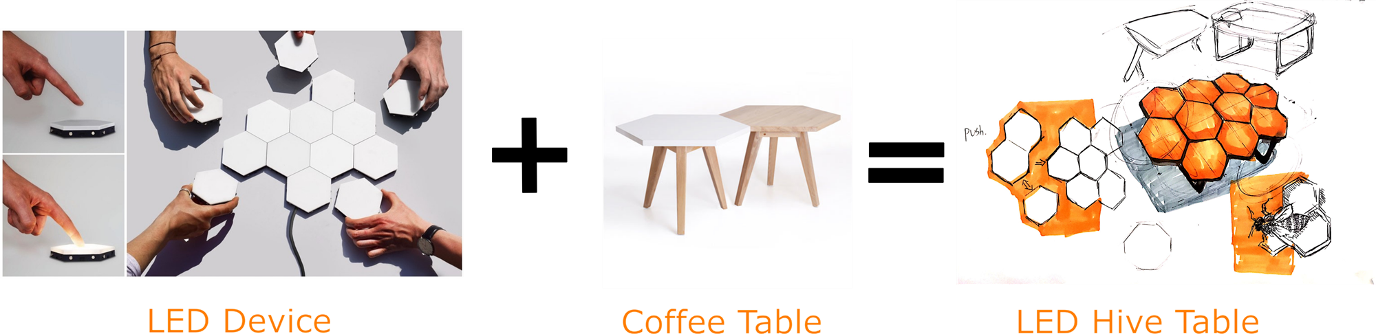
Conception:
My idea is to combine then together to be the Hive (LED) Table. The table use modular design. Each pieces of it is an indepenant table-module. So the table object can be easily saparated and combined. You can make it into a small coffee-table or you can make it into a large dining-table with more table-modules.

Prototype
Lasercutting kits outcomes:


Assembling and test with input and output devices.
Key points of design and difficulties
Structure part
Altough the magnets can hold the horizontal force but the table will also get the vertical force , so a another structure will be necessary.
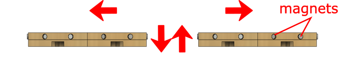
So I need to design a structure to make the whole overall structure stronger when they are combined together.
And I should deside ues which way for machining, CNC or lasercut or 3D print?
If I choose CNC, the point is how to maching double side.
If the lasecut is choosen, the point is how is thickness of the material.
If 3D print is the choosen one, the point is to ensure quantity(because there should be a lot of module to be made in the future).
Electrical part
To make the modules can communicate with each other I will use the I2C protocol, so there shoul be SCL, SDA, VCC, GND pins one each side of the hexagon edge. For each module will has its own powersupply(battery) VCC is not necessary, but GND should still remained for system stabilization.


For the function which I called Light domino, althrough the I2C can transform signal between objects, each module should need 2 pins to send/receive signal between each other. Because each module has its own adress(as slave), but no way to know which side it’s connectting to the other one. So, directly use 6 pins as IN and one pin as OUT is a easy way to realize that effect. Once the very module is triggerd it will use the OUT pin to send a signal, then each other module will receive its signal from their own IN pins…Then…OUT…IN…OUT…Then the domino effect should be realized.
Program part
There three main function for my project:
-
Single touch to light on/off the LEDs
Each module has its own power supply and own touch sensor. It can be turn on/off by single touch whether they are combined or separated. -
Domino light effect
Refference:
CONSTELLACTION from ◥ panGenerator on Vimeo.
- Comtrol with computer/apps
I will prefer to use Processing to make the interface for the system. Through processing to send a signal to the master MCU, then the master MCU will send command to the slave MCU. The slave MCU will follow the command that is received through I2C. The command sended by Processing is a string which should be like :
The whole process of my final project will be separated into 6 parts shown in the link below:
- Design development
- Computer controlled cutting
- Electronics design and production
- Input and Output devices
- Interface and application
- 3D print and casting (The next spiral. To make an anti collision edge with soft material through 3Dprintted mold and silicon rubber casting)