6. 3D Scanning and printing

Assignment
- group assignment:
- test the design rules for your 3D printer(s)
- individual assignment:
- design and 3D print an object (small, few cm3, limited by printer time) that could not be made subtractively
- 3D scan an object (and optionally print it)
To start with this weeks’s assignment,there is a website which is very useful to describe the professional term of 3D Scanning and printing scopes: http://reprap.org/wiki/Glossary
3D Scanning
Device: Kinect
Our Kinect is version 2.0. Download the Kinect driver(for Windows).

Software: Skanect & Meshmixer


Process:
Connected the Kinect to my computer and open Skanect.Then I can see the interface like the picture below. The blue means the object is too far away from the device, the red means too close, and the green means the distance between the object and device is moderate. And I adjusted the Object setting value into 0.7x0.7x0.7.


There are two way to scan. Move the device around the object or move the object itself. I choosed the next. I sat on a office chair which can twirl and I moved myself one round step by step until the scanning is finished. Here is the raw version of my 3D scan outcome. The original file is here. My Skanect account is for free, so it can just creat less than 5000 faces, which means the quality of my scanning is quite low.

As you can see there is a hole at my chin and the top of my head. Which means these area can’t be scaned.

So I use Fill Holes to process the defact.

Also I can use other basic process command like Move & Crop to adjust the position. Use color command to adjust color setting.
Then I used Meshmixer for futher processing. Such as Scuppt- Brushes, Falloff; Edit- Mirror, Plane cut are very useful command.

Then I tried to use Meshmixer to do some interesting things.
First I downloaded the file shown below from thingivers.
Then I inserted it into Meshmixer to make a boolean union with my body scanning.


Then I printed it!
(More detials of printing process I will show in 3D Printing.)
Support setting

Slice

Outcome


3D Printing
Modeling software: Solidworks & Fusion 360 & TinkerCAD(an online software and very easy to use)
Community: Thingivers
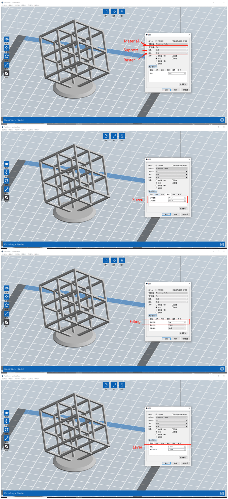
Slice software: Cura(good applicability, recommanded to use) & FlashPrint(just for my printer)
Machine: FLASHFORGE Finder 2.0

| Nozzle | Speed | Temperature | Size | Accuracy |
|---|---|---|---|---|
| 0.4mm | 10-100mm/s | 240℃ | 140 x140 x140 mm | 0.2mm |
Process:
Afer the group assignments for testing the design rules for our 3D printer. I tried to print an object that could not be made subtractively(at least with 3 axis cnc no).
The file I prepare to print on 3D printer:

Design process:
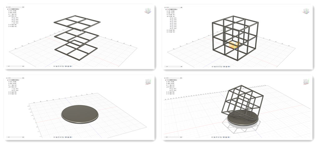
Slice process:
Simulation process:
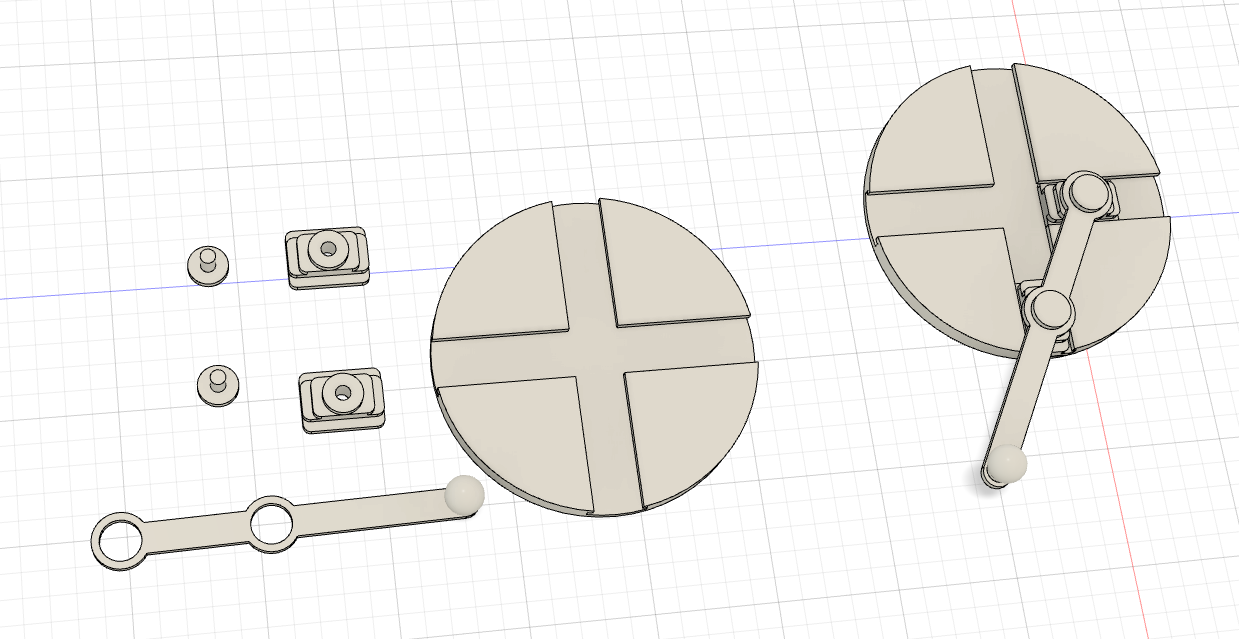
Moving part:
Then I tried to print a moving part:
Raw outcome without futher process.
 The supports and rough are cut off.
 But I broken the moving joint. The setting is not correct. I should set the clearance bigger than the thinnest width.

The advantage of 3D printing
To see the difference between subtractively(by CNC) and addition(by 3D printing). Most CNC machine are 3 axis, some 5 axis ones are very complicated and precise. 3D printer just need 3 axis. Not considering the material, 3D printing is a very useful technology to make a protopype. Here is the model:
With 5 Axis CNC:
Machine price: very expensive;
Processing time: very long;
With 3D Printing:
Machine price: cheap;
Processing time: just about 1 hour;
The other advantage of 3D printing is that it can simplify the number of parts.Here is one of my lastercut project. The project needs about 32 parts. But with 3D print technology, the number of part can be only 4(with right setting it can be even just 2).
By lasercutter:
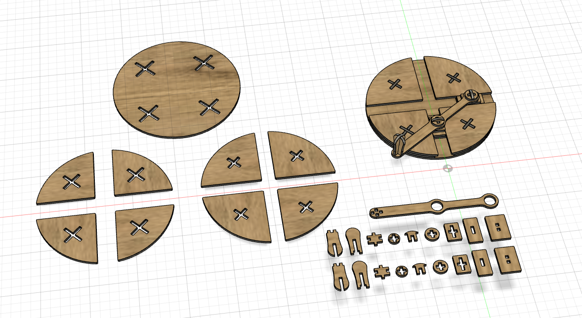
Look that…so many components…assemble them will kill me…
By 3D Printer:
haha…so few components…even a baby can assemble them quickly…