4. Computer controlled cutting
Group assignment:
- characterize your lasercutter’s focus, power, speed, rate, kerf, and joint clearance
Individual assignment:
-
Cut something on the vinylcutter.
-
Design, lasercut, and document a parametric construction kit, accounting for the lasercutter kerf, which can be assembled in multiple ways, and for extra credit include elements that aren’t flat.
4.1. Group assignment:
The Group Assignment page is at the following link.
Characterize our lasercutter’s focus, power, speed, rate, kerf, and joint clearance
This group assignment was done by my partner Lola Ojados and I together from our local node in Sedicup-Fablab, we are remote students of the Fablab León node.
(The documentation of the theory and characteristics of the machine has it collected by my partner Lola.)
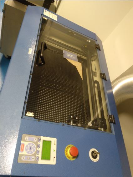
4.1.1. Identification of our laser cutter:
GCC LaserPro Mercury III
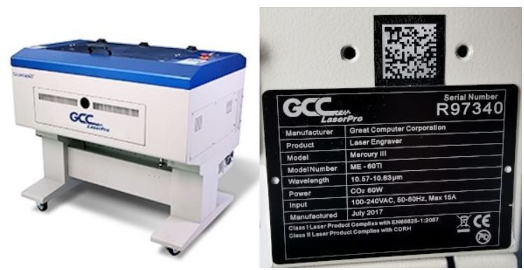
4.1.2. Mercury III description
Mercury III LaserPro is built by GCC (Great Computer Company) of Taiwan, making it the first laser to be imported from that part of the world.
Although the machine was assembled overseas, many of the most critical components were actually made in the US. Not only was the laser tube itself American made by Synrad™, the largest volume manufacturer of CO2 laser tubes in the world, motors and some of the electronics are also American-made.
Principles of a CO2 Laser:
LASER is the acronym for Light Amplification by Stimulated Emission of Radiation. A CO2 laser works by electrically stimulating the molecules within a carbon dioxide gas mixture. When focused through a lens, this highly-intense, invisible beam will vaporize many materials. Depending on the speed and intensity of the projected beam, a CO2 laser may be used to engrave or cut through a wide variety of materials.
4.1.3. Specifications of the laser cutter:
The machine specification data is listed in the following table: - GCC World
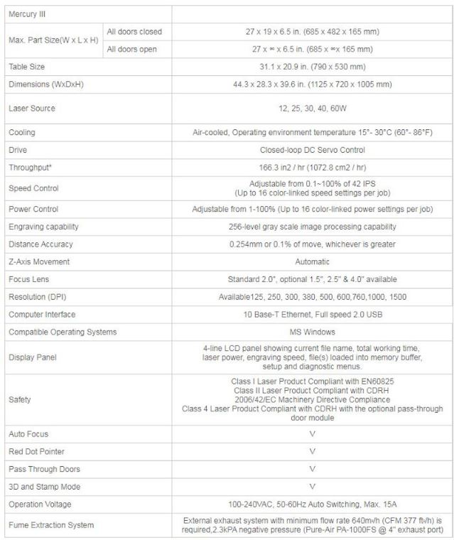
The laser source of our machine is 60W.
4.1.4. Focus of the Mercury III laser-cutter:
AUTO-FOCUS
Auto-focus is one feature that comes included with the Mercury III laser-cutter. Although there are people that prefer a manual focusing capability, manual focus is becoming a rare thing to find.
In the case of the GCC, there are research (1) that ensures GCC actually does focus correctly on almost every product—first time, every time.
(1) - informative articles
The mainly advantage of manual focus is when you want to roll something out of focus slightly. This is doing often when engraving rounded or curved products. With the GCC, it easy to adjust the amount the lens was out of focus using the mathematical readout on the display. It is actually far more precise than focus the machine manually.
The GCC uses a different approach altogether to other laser-cutter. Instead of using an infrared light beam to find the thickness, the GCC uses a pressure-type switch mounted to the lens assembly. Because the lens assembly can be moved manually to any position on the table, even products with uneven surfaces can be easily registered accurately. For those, really tricky products, there is a simple drop-in tool that allows manual focusing or allows the engraver to double-check what the autofocus is doing.
One of the true advantages of the excellent focusing capability is how it increases the machine’s ability to cut thick materials. In cutting, it is important to be able to focus as much light energy as possible into the tiniest area. When comparing the machine’s cutting ability with the beam focused automatically and manually, the laser was capable of cutting much thicker materials when auto focused, even when I tried my very best to manually focus the light beam as precisely as I possibly could.
4.1.5. Power of our Mercuy III laser cutter:
The maximum power of the machine is 60W. (CO2 Laser source). As it appears in the specifications, the machine has POWER CONTROL adjustable from 1 - 100% (Up to 16 color-linked power settings per job). In the work of characterization of the machine, we have calculated the power and its ratio for the range of materials with which we usually work in our laboratory. Differentiating also in some of the cases between different thicknesses of the same material.
4.1.6. Speed of our Mercuy III laser cutter:
As it appears in the specifications, the maximum speed of the machine is 42IPS. (Inch Per Second). The Mercury III laser cutter machine has SPEED CONTROL adjustable from 1 - 100% (Up to 16 color-linked speed settings per job). In the work of characterization of the machine, we have calculated the speed and its ratio for the range of materials with which we usually work in our laboratory. Differentiating also in some of the cases between different thicknesses of the same material.
4.1.7. Rate of our Mercuy III laser cutter:
As we have indicated in sections 5 and 6, in the process of characterizing our laser cutter, we have calculated the speed rate and power rate for the range of materials and thicknesses used in our laboratory.
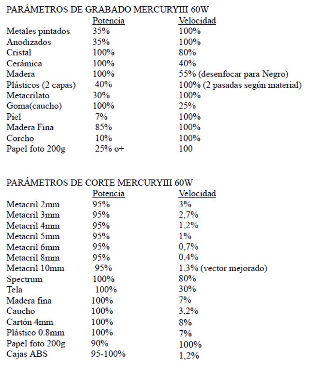
The starting information of the engraving and cutting parameters is in these two tables:
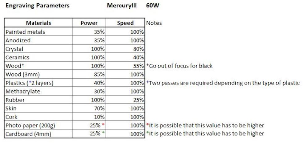
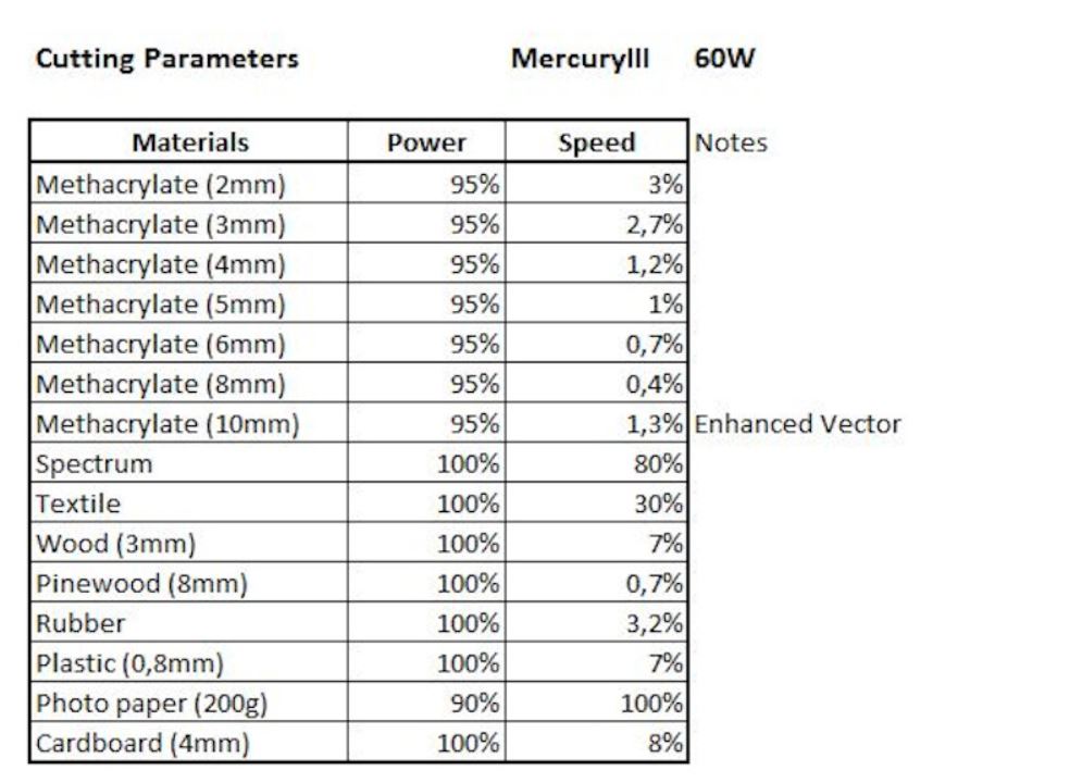
In the results section, we have detailed and updated all this information.
4.1.8. Kerf of our Mercuy III laser cutter:
For the calculation of the kerf, we must first know the distance “d”, which is calculated as the difference between the design dimension and the actual dimension of the cut object. Thus we know the thickness of the material that the laser burns by making the cut for each of the materials tested.
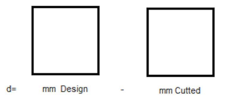
The kerf is the average value of that distance “d” and we have had it for the different materials we use.
Kerf = d / 2
4.1.9. Joint Clearance (offset of our parametric design) of our Mercuy III laser cutter:
The joint clearance is the distance between mating surfaces of a joint.
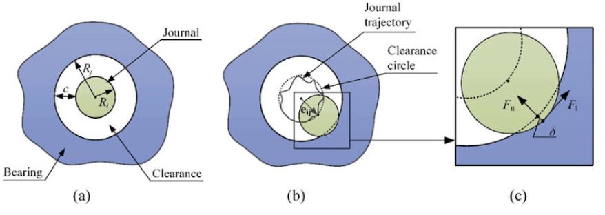
Model of clearance joint: (a) Nominal case, (b) Contact mode, and (c) Details of contact area.
4.1.10. Results
(I have done this part)
Depending on the material we cut or engrave with the laser cutter we will have to configure the speed and power parameters. The manufacturer gives us general values for different materials.
NOTE: DO NOT USE PVC, TOXIC VAPORS!
But these values may vary from one brand to another. Therefore, we have to check it for the materials we have. In addition we also get different kerf values. To test the values we have done cutting tests.
4.1.10.1. Velocity and power tests
To use our machine we have to use the CorelDraw software, in which our machine is already predefined as a printer.
We will make a simple drawing to test the speed and cut parameters in our materials.
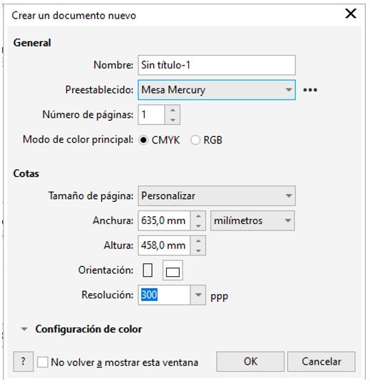
We open CorelDraw and create a new document.
A window opens to configure the worktable.
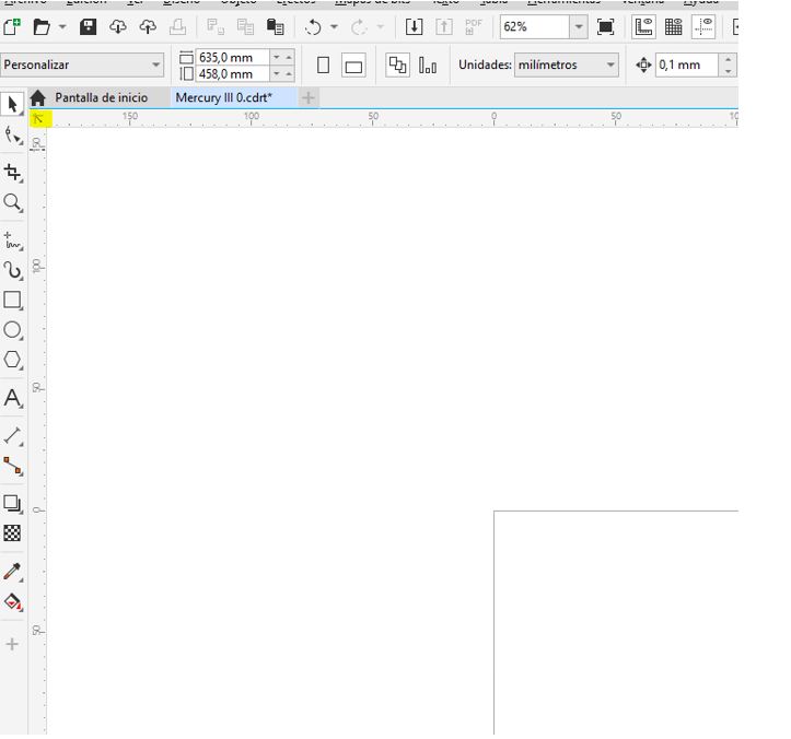
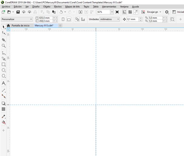
We click and drag on the next icon to set the zero of the template in the upper left corner to match the zero machine.
Now I select the rectangle tool and draw it in the template. I unlock the relationship between width and height, and introduce the measures that I want the rectangle to have.
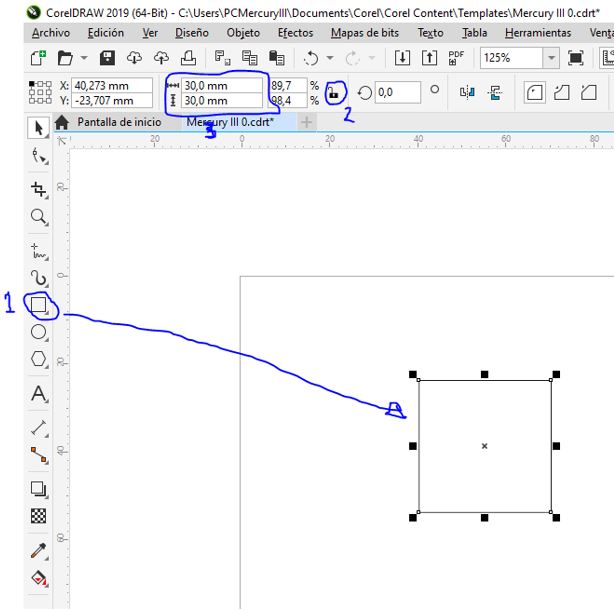
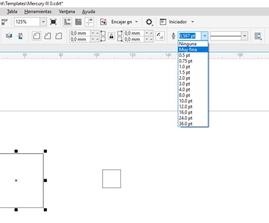
With the contour that I want to cut selected, I set the contour width. Less than 0.1mm means cut and higher engraving, so we select ‘Very Fine’ which is a value of less than 0.1mm assigned by this program for cutting.
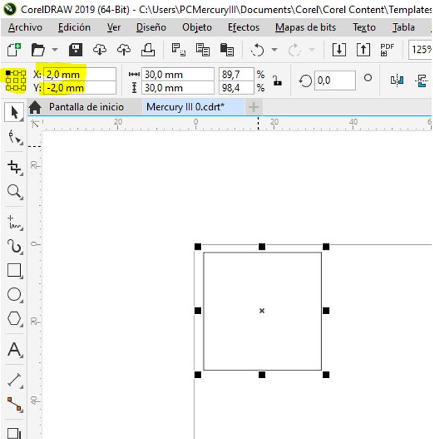
We align with respect to the zero machine. Select the object origin in the upper left corner and enter the coordinates. The minimum distance from zero of the machine at which we can place the object in x: 2mm y: 2mm when it comes to cutting (if it were recorded if we can put 0.0).
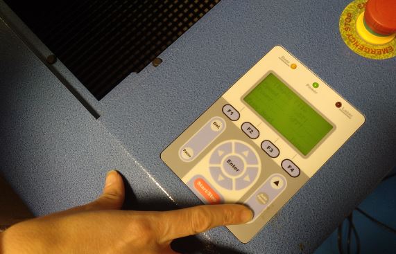
Now we configure the machine.
Depending on the color assigned to the contour or fill of the designed objects, the machine assigns an order of execution. And for each color we will assign the speed and power parameters. What determines whether it is a cutting or engraving operation are these two parameters and the material we are working with. The other determinant is the thickness of the line that we indicate in the software, if it is very thin, a cut or perimeter engraving will usually be made in the case where we give it more speed or less power.
We select the color of black contour for the square inside, and the red color for the square outside. This will be the first cut inside and then the outside.
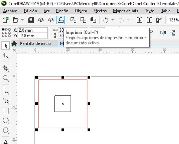
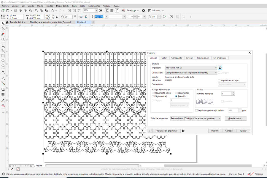
We select the printer. We mark the selection option and click on the gear to configure.
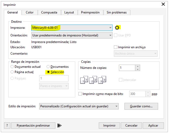
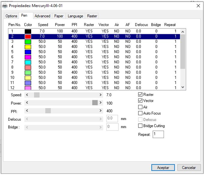
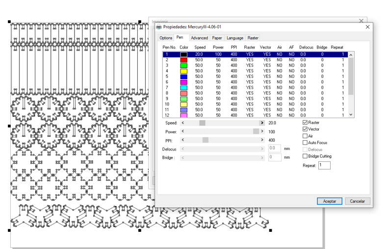
In this window, in the ‘Pen’ tab, we assign the parameters to each color.
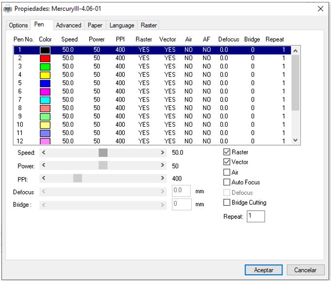
We assign the values for cutting in fine wood to black and red.
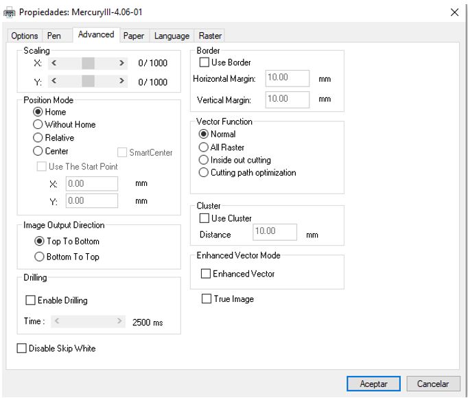
In this tab we can configure the machine to take as a reference the point that we indicate manually (moving the head with the buttons on the panel) to match the center of the object drawn using the ‘Center’ option. We will leave it with the default option, ‘Home’.
Ready! We accept and give you to print.
Now we are going to prepare the material that we are going to cut. We open the door and lower the bed to put the material without touching the head.
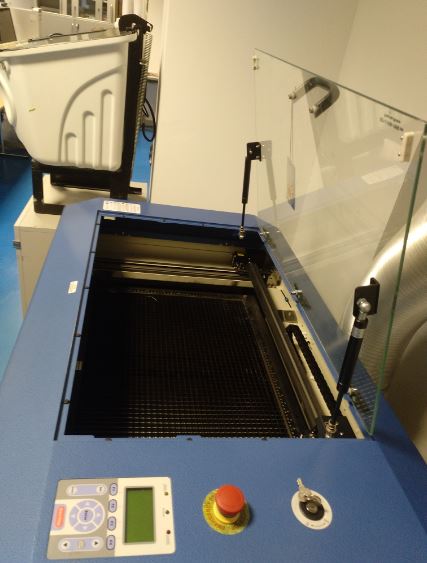
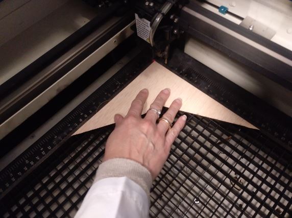
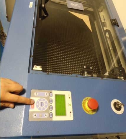
With the arrows we move the head to place it on top of the material and then we give ‘Auto Focus’.
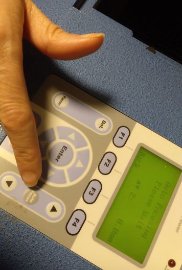
It is already calibrated.
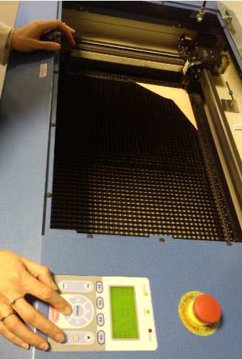
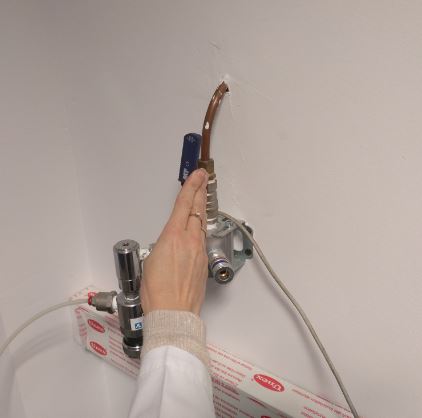
Now we close the lid, open the CO2 valve, activate the aspiration and press ‘Start’. Note: While the machine is cutting we should not leave it without supervision.
We have tested the parameters of speed and power to cut different materials.
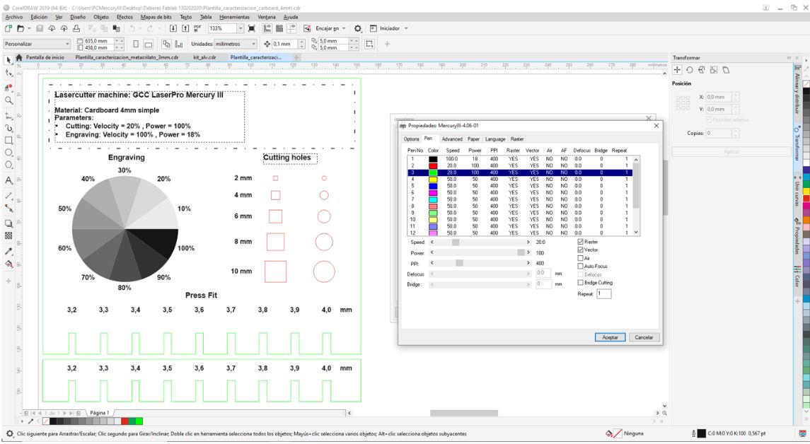
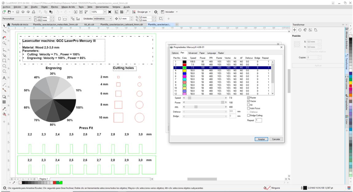
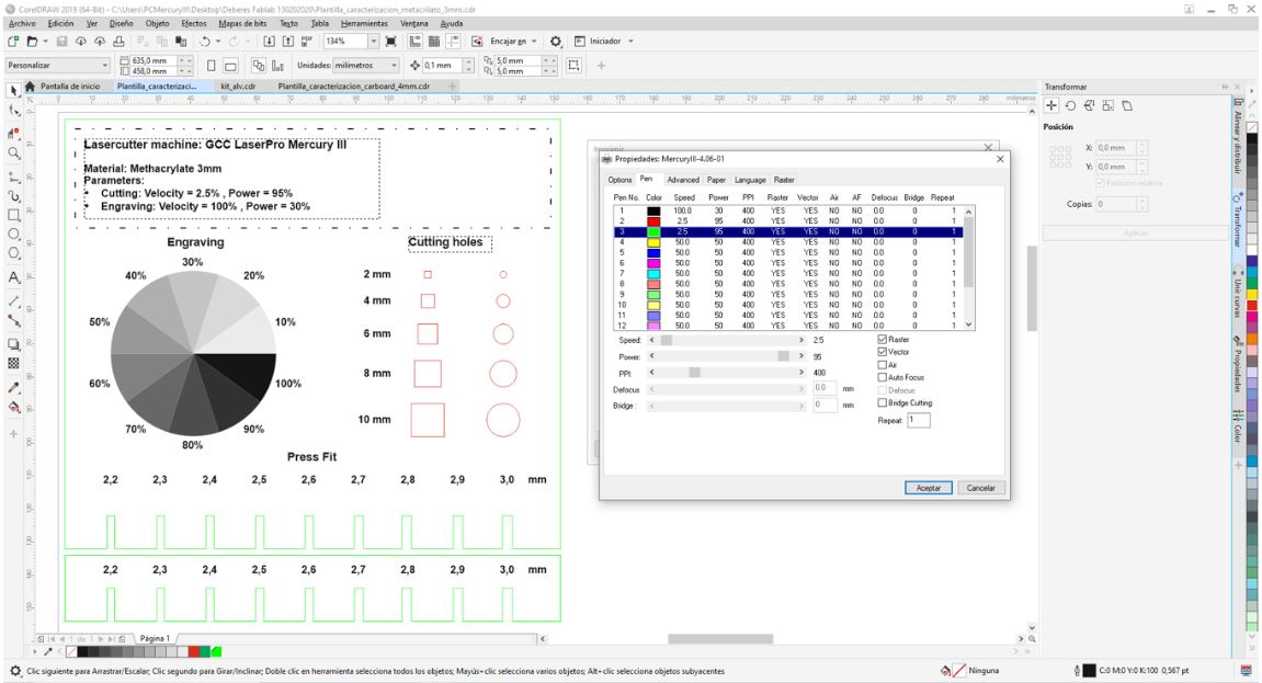
4.1.10.2. Sample templates
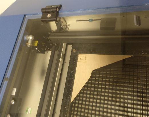
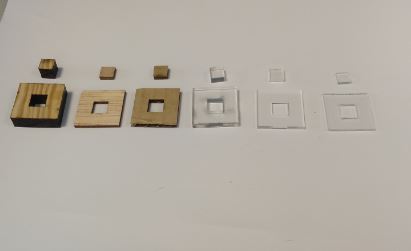
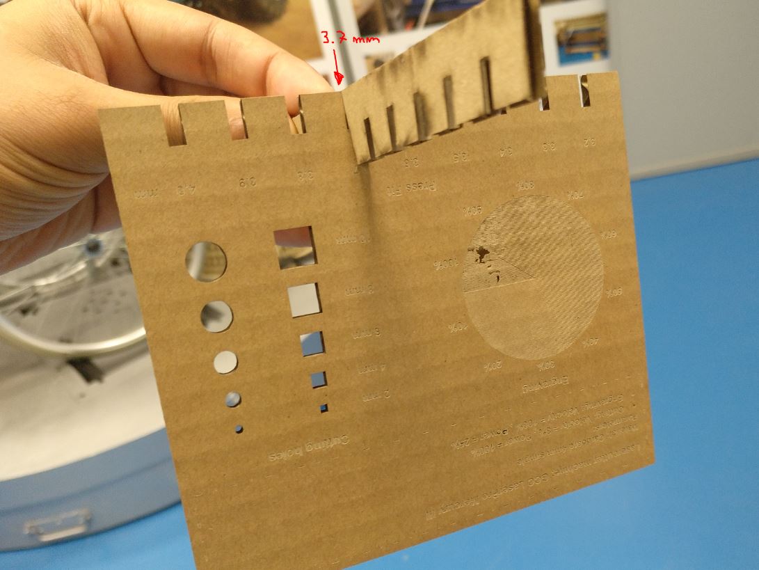
Finally, we cut a sample template for each material in which the parameters selected to perform it are described and it helps us to visualize the engraving of a raster image with different shades of the gray scale. It also helps us to measure the kerf and choose the pressfit.
I have taken the idea of the template of a student from last year of Barcelona fablab, Gustavo Abreu.
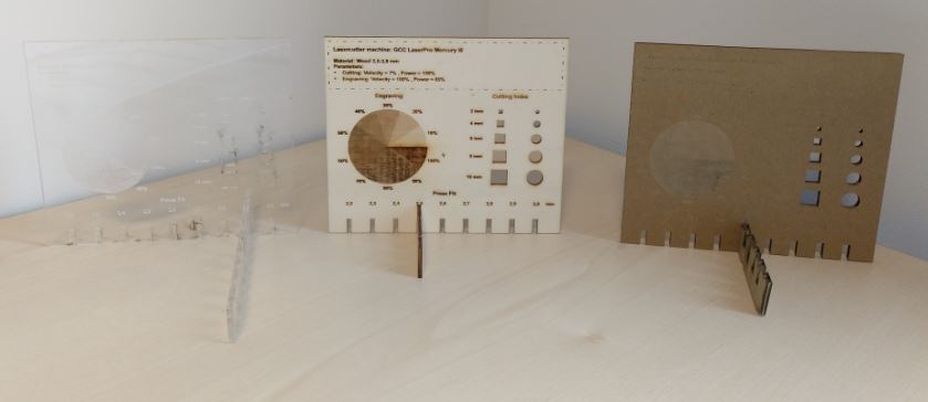
4.1.10.3. Difference and kerf
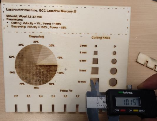
* Wood 2.5mm :
Parameters cutting : V=7% , P=100%
Parameters engraving : V=100% , P=85%
Difference=0.15mm
Kerf=Difference/2= 0.075mm
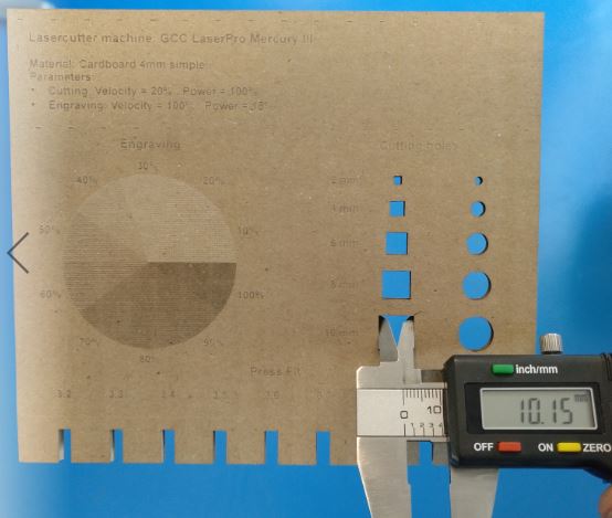
* Cardboard 4mm :
Parameters cutting : V=20% , P=100%
Parameters engraving : V=100% , P=18%
Difference=0.15mm
Kerf=Difference/2= 0.075mm
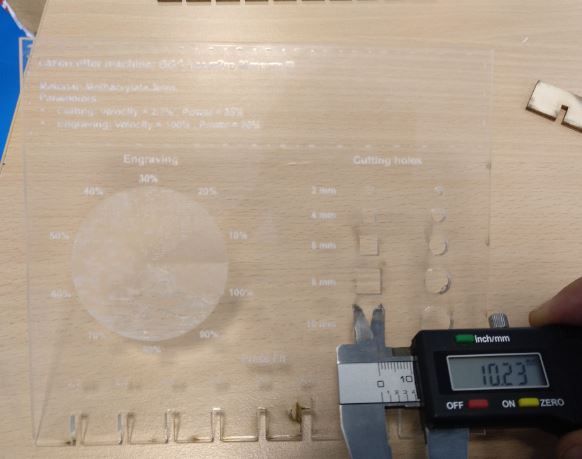
* Methacrylate 3mm :
Parameters cutting : V=2.5% , P=95%
Parameters engraving : V=100% , P=30%
Difference=0.23mm
Kerf=Difference/2= 0.115mm
4.2 Individual assignment
- Cut something on the vinylcutter.
- Design, lasercut, and document a parametric construction kit, accounting for the lasercutter kerf, which can be assembled in multiple ways, and for extra credit include elements that aren’t flat.
4.2.1 Vinyl cutter
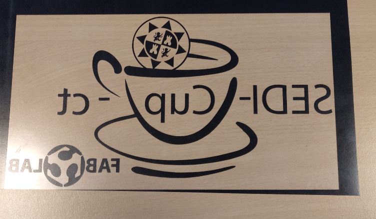
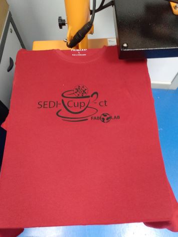
My vinyl cutter is GCC Jaguar IV. Its maximum width is 1320mm. I will use textile vinyl to stamp on a t-shirt the logo of my fablab.
4.2.1.1 Machine preparation
First pull the side lever to release the material inlet.
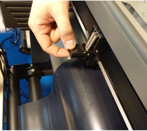
I introduce the vinyl and place the rollers so that they are on the vinyl and also match some of the white marks.
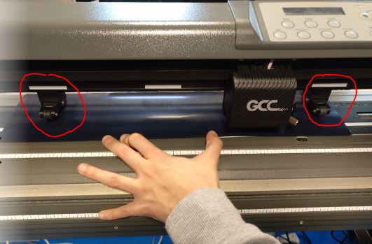
I press the back tab of the rollers that I placed earlier to fix them.
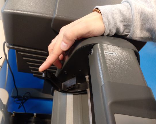
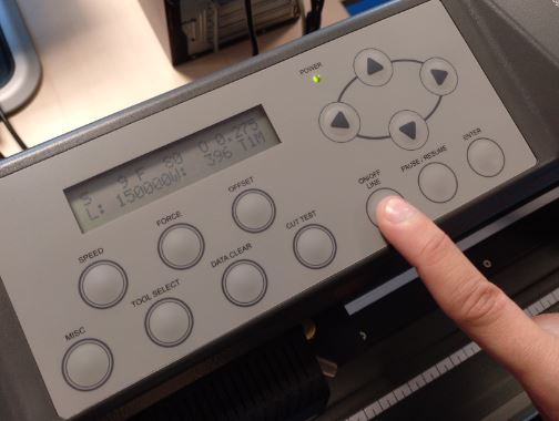
I press the down arrow so that the machine detects the edge of the vinyl.
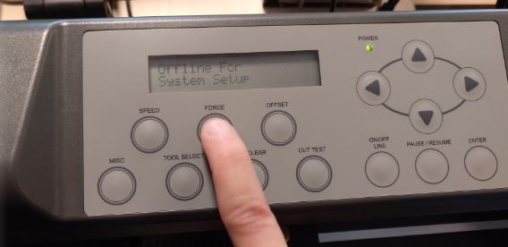
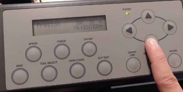
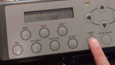
Press the ‘ON / OFF LINE’ button to set the cutting parameters. Then I press the ‘FORCE’ button and set the cutting force, for my vinyl it is 60 gF. And press the ‘ENTER’ button to accept and again the ‘ON / OFF LINE’ button to leave the machine ready.
4.2.1.2 Control software
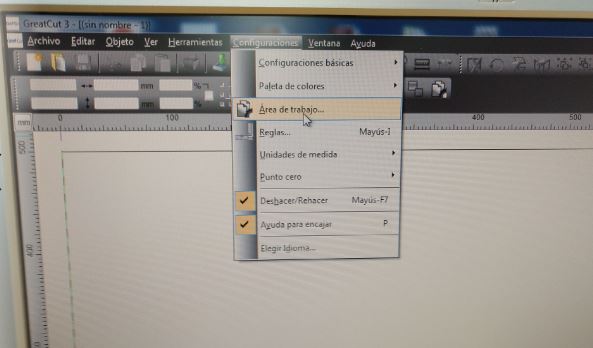
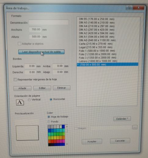
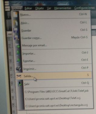
To control the vinyl cutter we use the GreatCut 3 software.
We open a new file and configure the cutting parameters. To do this, we click on ‘Settings’, ‘Work area’. And click on ‘Read current output device’ to be configured with the machine.
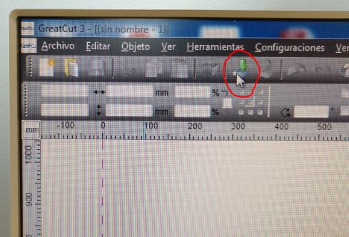
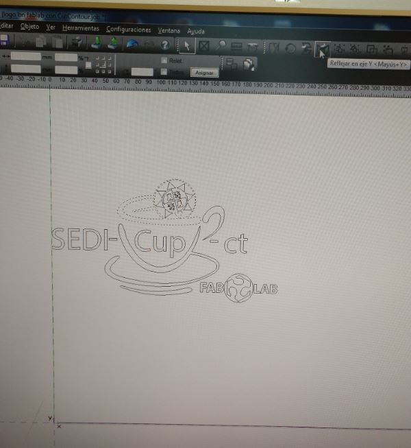
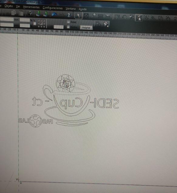
I click on the green arrow icon to import the vector file. And I assign the line contour for cutting. We need the mirror image since it sticks on the face that is cut, so we click on the ‘mirror’ icon.
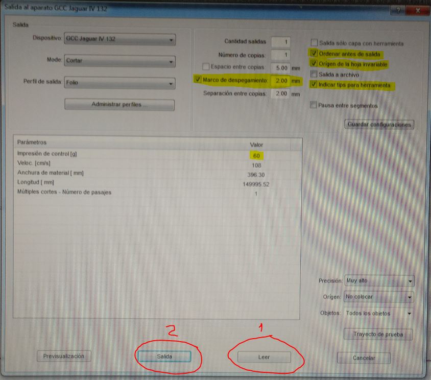
Finally I click on ‘File’, ‘Output …’ to open the cut configuration window. We click on read and select the options as shown in the following figure. And finally we click on ‘Exit’ and the machine will start cutting.
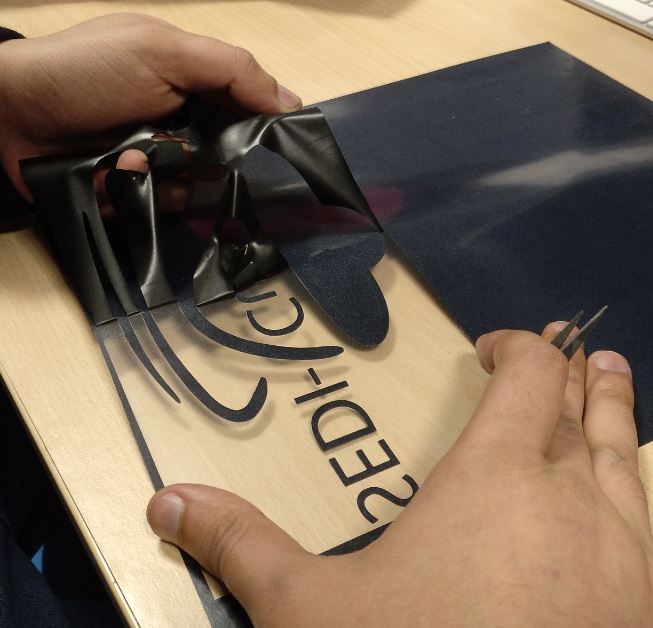
This type of vinyl has a transparent layer that serves to transport the cuttings keeping the relations between them. With the help of a clamp, remove the remaining parts.
Easily removed!!!
4.2.1.3 Stamping
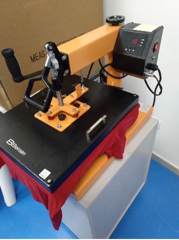
I used the Beinsen thermal press for stamping.
First I select the temperature according to the type of vinyl. For this vinyl the temperature has to be 150ºC. Then I select the ironing time, 15s, and wait for it to warm up. While I put the shirt and the vinyl.
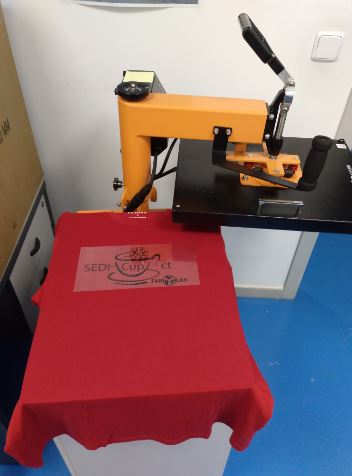
After 10 minutes, the iron is already hot. Under the lever to press and a countdown is activated that warns me of the weather. When I finish I lift the press and go!
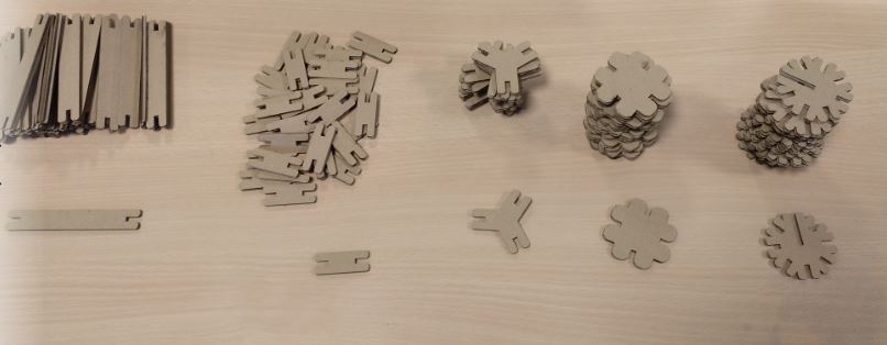
4.2.2 Design and cut of a parametric kit
4.2.2.1 Design a parametric kit
I have used Solidworks software to make the parametric design of my pieces.
I saw this tutorial for solidworks parametric
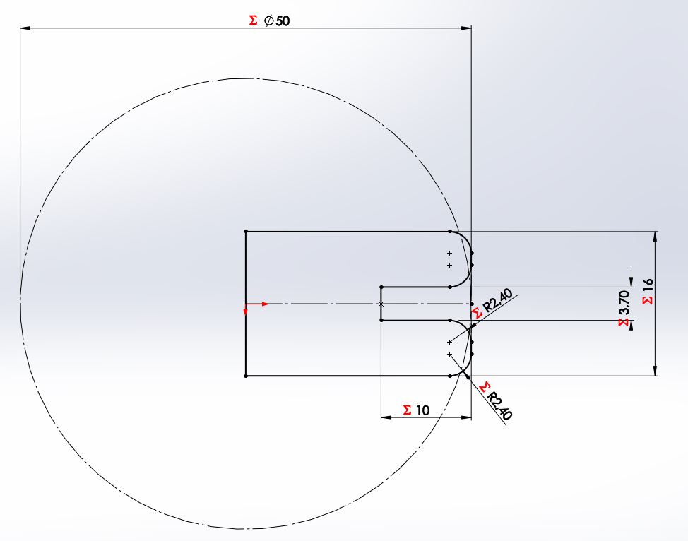
First I defined my variables by clicking on ‘tools’, ‘equations’. Working with the variables allows you to quickly adjust the pressfit according to the material, and also allows you to vary the geometries. I am going to use 4mm thick cardboard (t = 4mm). I check that with 3.7mm hole the pressfit gets enough grip.
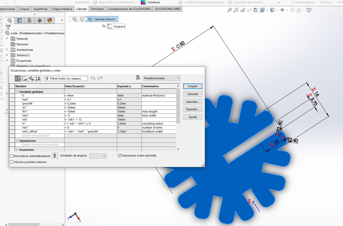
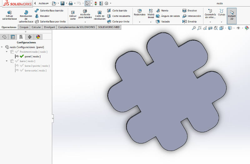
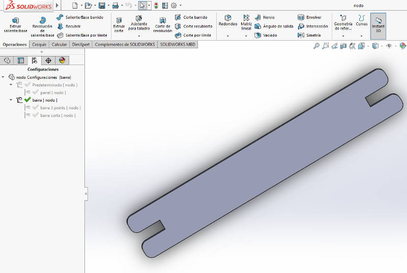
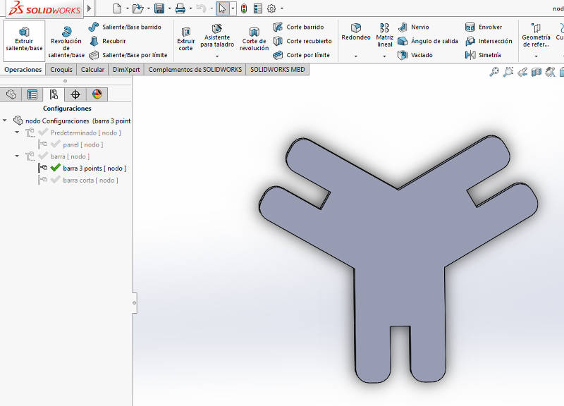
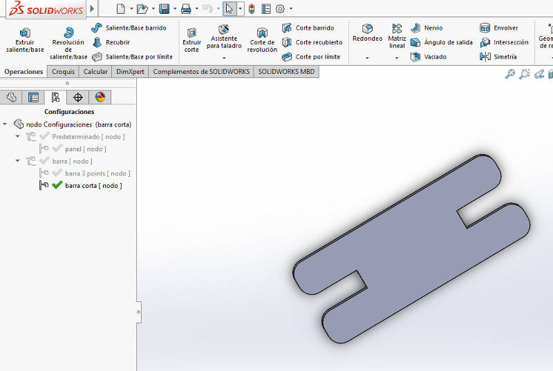
Now I have designed my basic piece relating its dimensions to the variables.
In the ‘ConfigurationManager’ tab I add configurations for the different parts by modifying the values of the variables.

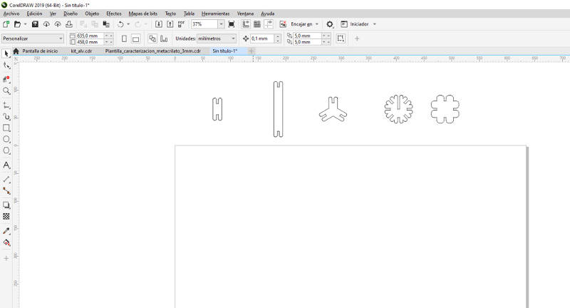
To get the drawing of the pieces I click on ‘File’, ‘Create drawing from piece’. I put the front view of each piece configuration, I make sure that the scale is 1: 1 and save the drawing in pdf format.
4.2.2.2 Cut a parametric kit
I import the pdf file of my pieces in the CorelDraw software, and I adjust and duplicate it until the size of my material is filled.
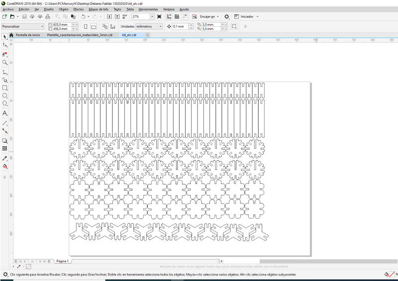
I set the cutting parameters for cardboard (velocity 20% and power 100%) and set the machine to be cut.
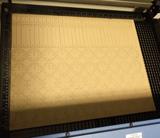
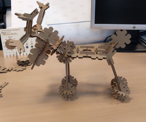
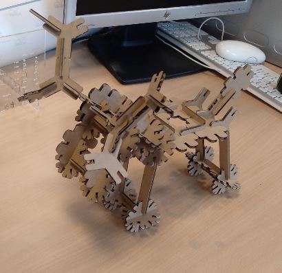
I already have my parametric kit !!! Now it’s time to play. I have let my imagination fly and I have built a deer.
4.3. My files
- Templates for laser cut characterization:
Template_characterization_cardboard_4mm
Template_characterization_metacrilato_3mm
Template_characterization_wood_3mm
- My parametric kit for laser cutting: