9. Embedded programming
-
Individual assignment:
-
Read a microcontroller data sheet
-
Program your board to do something, with as many different programming languages and programming environments as possible
-
-
Group assignment:
- Compare the performance and development workflows for other architectures
9.1. Group assignment
The Group Assignment page is at the following link.
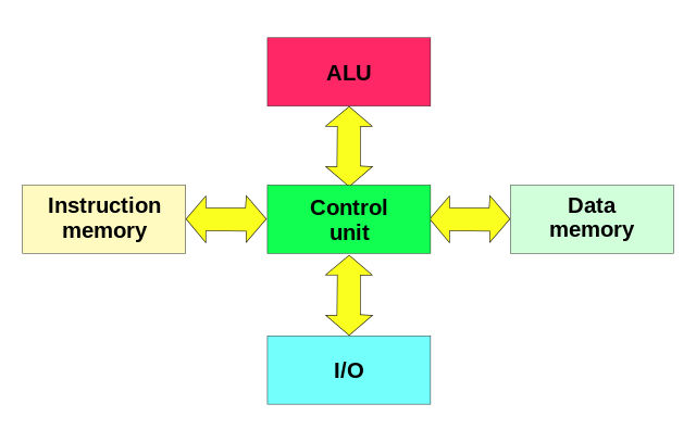
In this link, we found a description of the types of microcontroller architecture that exist.
Some types of microcontroller/processor architectures:
-
Harvard Architecture:
- Texas Instruments TMS320 C55x processors.
- The AVR microcontrollers from AVR from Atmel Corp and the PIC from Microchip Technology, Inc ..
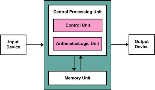
- Von Neumann architecture:
-
ARM architecture:

- ARM microcontrollers family.
- Raspberry Pi boards, STM32 microcontroller,…
-
RISC achitecture:
In computational architecture, RISC (from English Reduced Instruction Set Computer, in Spanish Computer with Reduced Instruction Set) is a type of CPU design generally used in microprocessors or microcontrollers with the following fundamental characteristics:
- Fixed-size instructions presented in a small number of formats. - Only the loading and storage instructions access the data memory.
9.1.1. Workflows for AVR microcontrollers (Harvard Architecture)
9.1.1.1. Development environment for AVR.
Setup for all of your AVR programming
These steps will only have to be done the first time to configure our USBtinyISP programmer and toolchain.
Summary:
-
Install Git
-
Install the Atmel GNU Toolchain
-
Install GNU Make
GNU Make is a tool which controls the generation of executables and other non-source files of a program from the program’s source files.
-
Install avrdude
AVRDUDE (software for programming Atmel AVR Microcontrollers)
-
Update your PATH
We need to tell Windows where to locate all of the tools you’ve just installed when you type their names on the command line.
Start menu > Control Panel > System > “Advanced System Settings” > “Environment Variables” >”Path” > “New”
The three values to add are:
C:\Program Files\avr8-gnu-toolchain\bin
C:\Program Files (x86)\GnuWin32\bin
C:\Program Files\avrdude
-
Install Drivers for your Programmer
The USBtiny programmers use a generic libusb driver, but Windows 10’s driver signing policy makes the installation more complicated. Fortunately, there’s a tool that helps with this. Download Zadig and launch it. Plug in your programmer, and select the “USBtinySPI” device in the list. (If it doesn’t show up, go to the Options menu and click “List All Devices”. The driver you want to install (to the right of the green arrow) is either libusb-win32 or libusb0. Click the “Install Driver” button. You should only have to do this once.
-
Sanity Check
In Git Bash:
make –v

avr-gcc –version
Connect your programmer to a USB port
avrdude -c usbtiny -p t45
9.1.1.2. Set the programmer ATtiny45
-
Get and Build the Firmware AVR.
Download and extract the firmware source code
In GitBash: cd (source code directory)
makeThis will build the hex file (fts_firmware.hex) that will get programmed onto the ATtiny45.
-
Program the ATtiny45
Edit the file called Makefile with WordPad.
Near the top of the file, find the line that says:
PROGRAMMER ?= **usbtiny**and change usbtiny to whatever programmer you’re using:
-
Small translucent blue programmer: avrisp2
-
Large translucent blue programmer: jtag2isp
-
White box with blue stripe: atmelice_isp
-
Any fabbed board with an ATtiny on it: usbtiny
-
Plug the board into a USB port. In GitBash:
make flash
This will erase the target chip, and program its flash memory with the contents of the .hex file you built before.
make fuses
This will let the chip use the reset pin to program other boards, but will disable the ability for this chip to be programmed again.
- Blow the Reset Fuse
9.1.3. Programm an AVR board using the USBtiny
Use the programmer with a hello board using the Arduino IDE. To do this, load the libraries for attiny programmers.
http://fabacademy.org/2019/docs/FabAcademy-Tutorials/week08_embedded_programming/attiny_arduino.html
9.1.2. Workflows for ESP32 microcontrollers (Xtensa LX6 Architecture)
To program this board we can use the Espessif tools or using the Arduino IDE.
9.1.2.1. Espressif IoT Development Framework (IDF)
This link explains the steps to configure the programming environment.
In Windows:
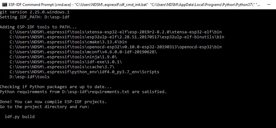
- Install toochain
At the end of the installation the console opens and this appears:
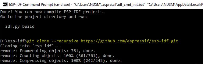
- Clone libraries
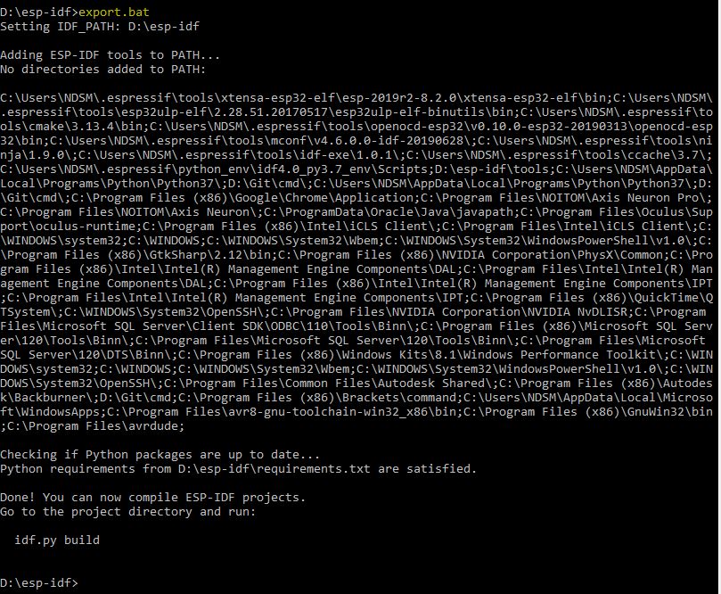
- Set up the environment variables
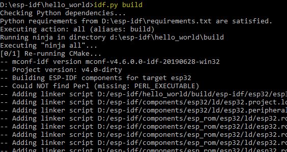
- Build a project. Build the hello-world example from the libraries.
Type “cd hello-world” and then:
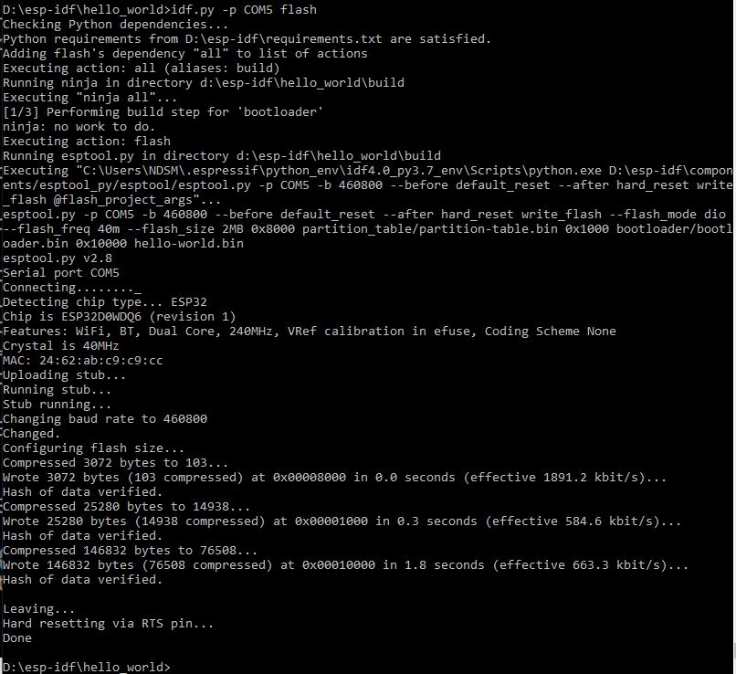
- Flash onto the Device
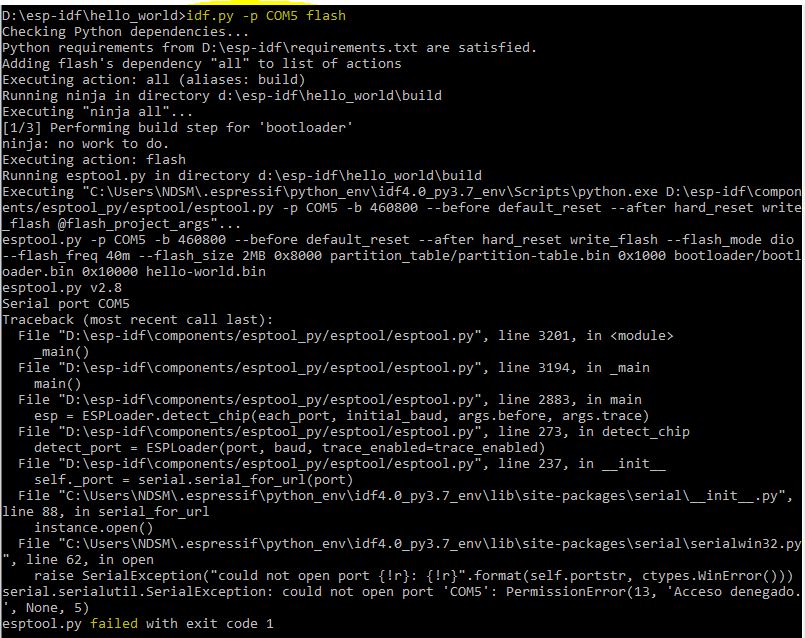
Error!!! I have to push the RST buttom and then type it again.
- Open the IDF Monitor to check if “hello_world” is indeed running.
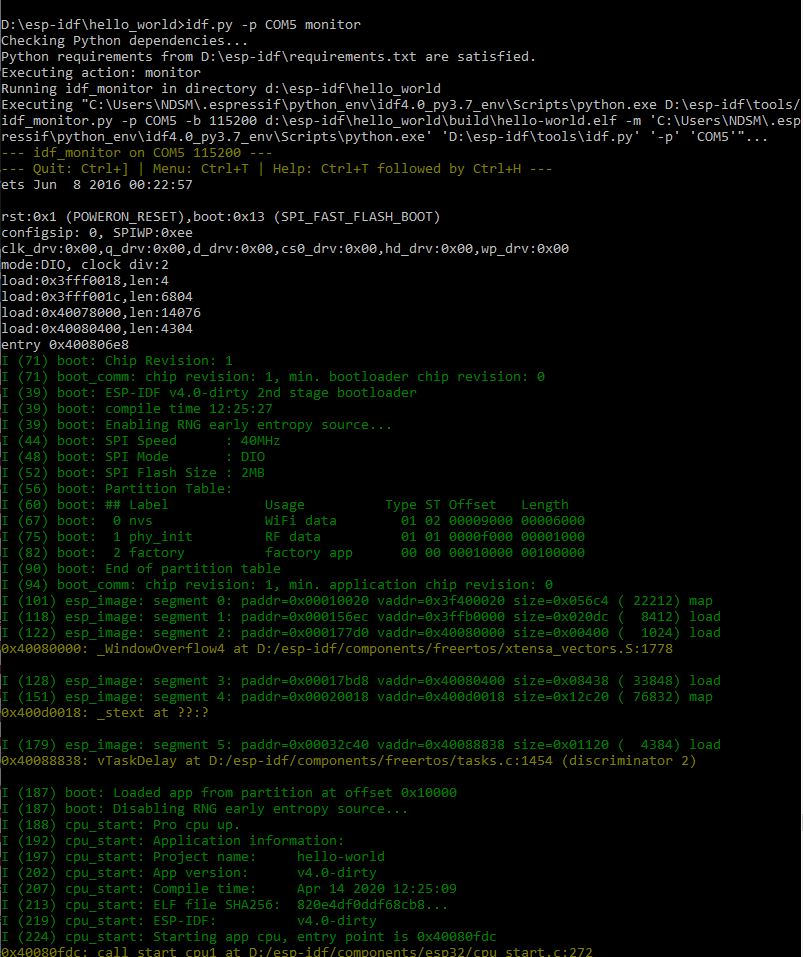
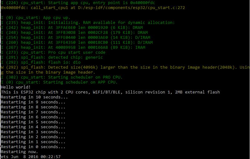
Note: (ctrl+[ ) to close the monitor
9.1.2.2. Arduino IDE
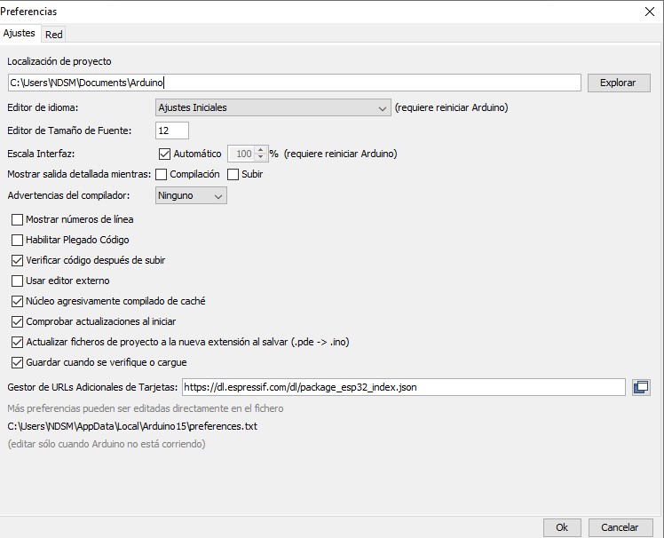
- In “Preferences” paste the URL to get the esp board
https://dl.espressif.com/dl/package_esp32_index.json
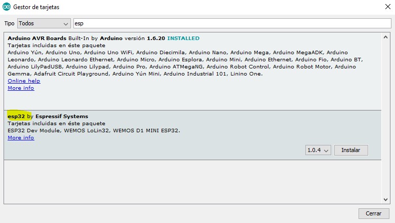
- In “Board management” install “esp32”
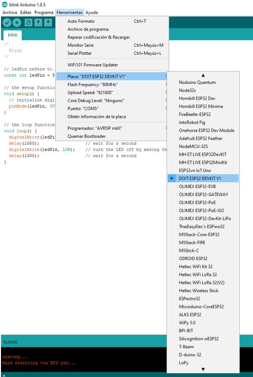
- Select the board “DOIT ESP32 DEVKIT V1”
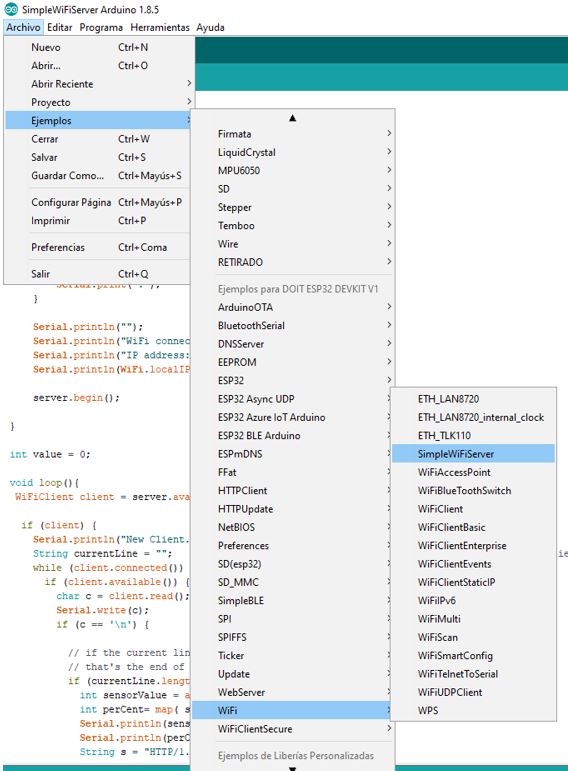
There are many examples to learn how to program it.
9.1.3. Workflows for ARM microcontrollers (ARM Architecture)
ARM is 32 bit Instruction set (CPU) Architecture or Microprocessor while AVR is family of microcontroller.
ARM can be both used as Microcontroller or as Microprocessor (Coretx M series or Cortex A series) while AVR used only as Microcontroller.
ARM has high Processing power as Compare to AVR.
Any OS can be installed on ARM based machine but no such facility in AVR.
More memory in ARM while less RAM/ROM Used in AVR.
ARM is mostly 32 bit while Avr comes in 8/16/32 bit variant.
ARM is High speed and Costly while AVR is cheap and effective.
The toolchains for the ARM family are practically the same as for the AVR family.
We currently don’t have access to the fablab so I won’t be able to test it.
9.2. Individual assignment
I have the ATtiny44 Hello board I made earlier for another assignment, so I’ll try to program it using different enviroments and languages.
9.2.1. Read a microcontroller data sheet
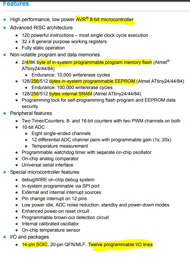
First I read the datasheet of attiny44. It is difficult to understand but I draw some conclusions.
Microprocessor characteristics. I underline those that I can understand …
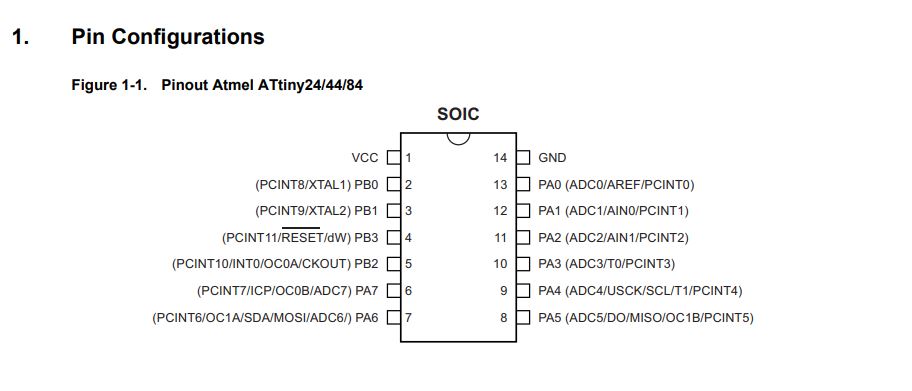
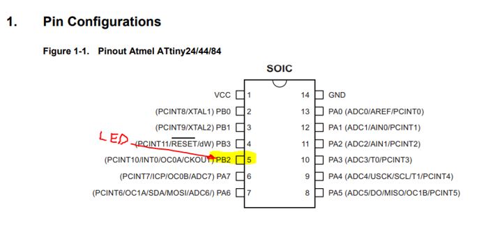
In the pin configuration I can see the distribution of the pins with the functions they have. This information is very useful when designing and programming a board.
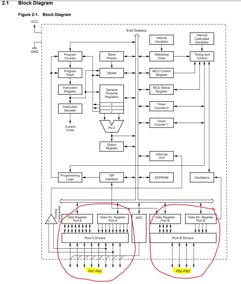
In the Block Diagram I can see the structure of the elements that make up the programmer. Hard to understand. I can understand that there are 2 separate ports for inputs and outputs with their respective pins. Each port will have a different characteristics.
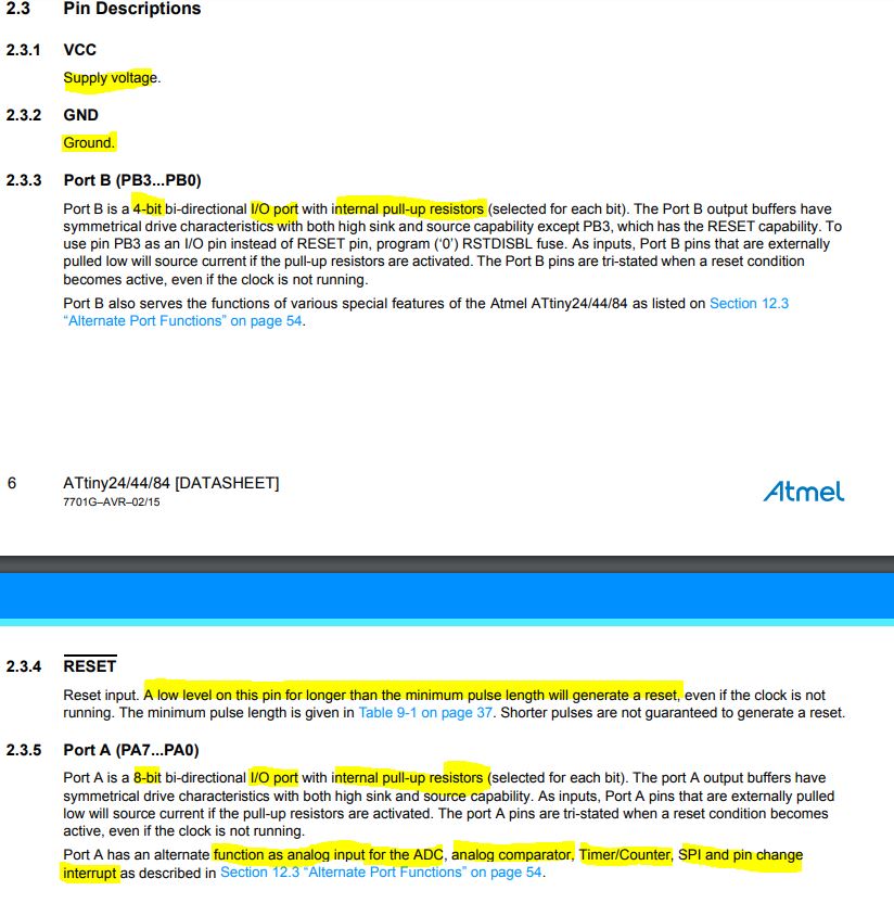
In Pin Description explain the differences between these two ports.
9.2.2. Program my board
I am going to program my hello44board using the UsbTinyISP programmer, which I did previously, in different ways.
The toolchain I already have installed from the previous assignmet. In that subject I already tried to program my board using Arduino IDE, anyway I will count it again.
Also I will try to program it in other ways.
9.2.2.1. Programming with Arduino IDE
9.2.2.1.1. Preparing Arduino IDE
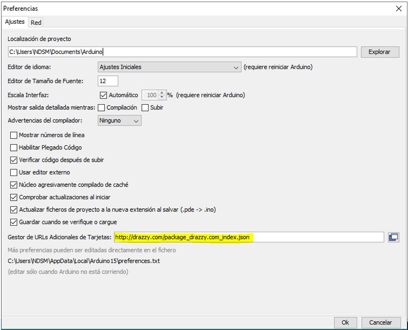
First you have to tell Arduino IDE the URL where to find the package to work with the Attiny boards.
In Archive> Preferences
Paste http://drazzy.com/package_drazzy.com_index.json
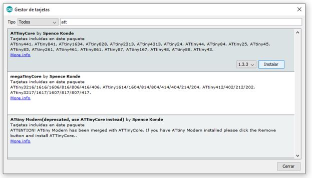
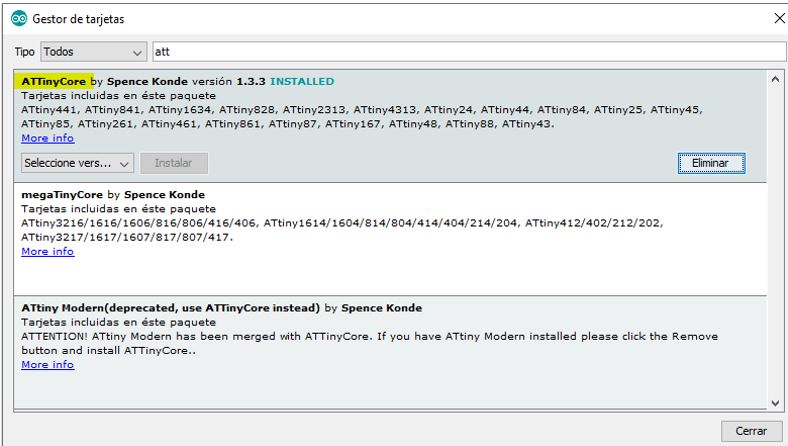
Then go to Tools> Board> Board manager
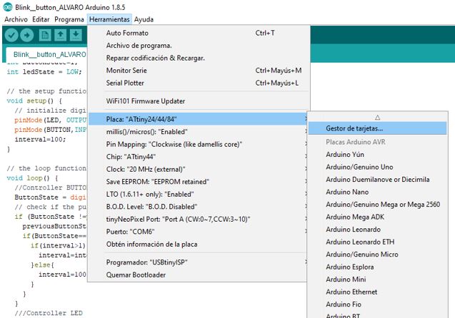
Find ATTinyCore package and install.
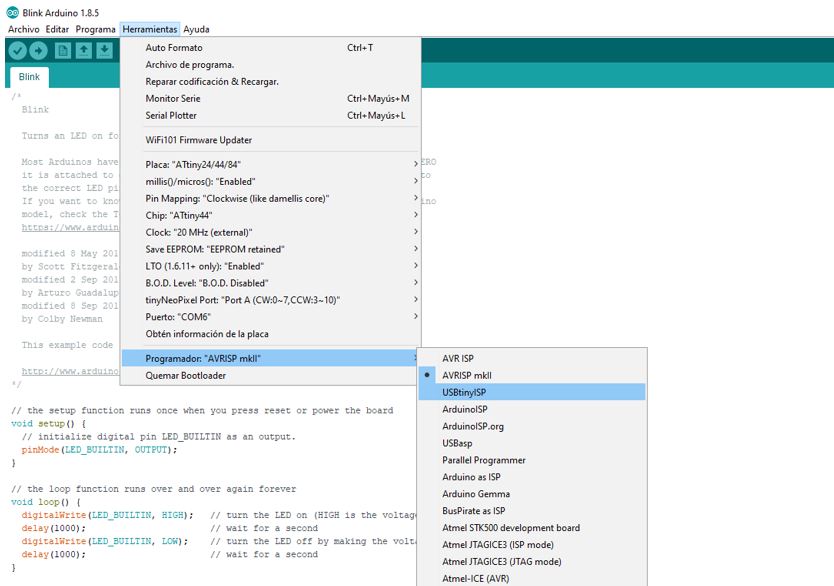
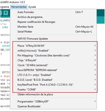
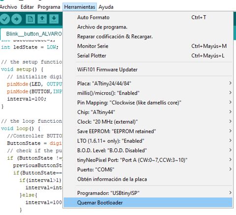
Now we select the parameters of our board in Tools:
Now configure the fuse bits of the microcontroller. Click Burn Bootloader.
Note : This step is important to configure the clock. The first time I skipped it, and the delays didn’t last as long as I wanted
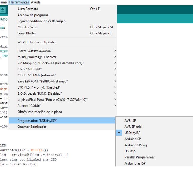
Select the programmer that we are going to use, USBtinyISP.
And to program ..
9.2.2.1.1. Programming
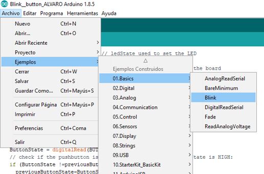
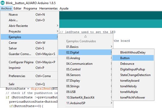
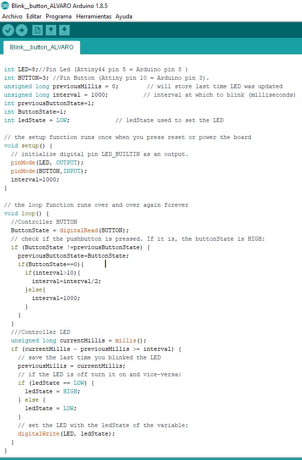
For my code I have mixed several examples that are in Arduino IDE.
- Blink
- Button
- BlinkWithoutDelay
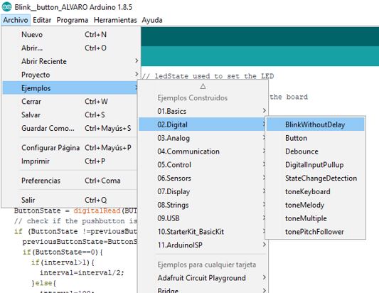
- My Code
9.2.2.2. Programming with GitBash
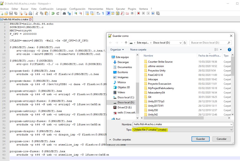
From GitBash I can program the board using the toolchain. We will need the code in C in a .c file and the .make file.
To generate these files I had to use NotePad ++ to save them with the corresponding extension.
Note: The first time I used WordPad and they were created as text files for me.
Now in GitBash I go to the directory where the files are using the cd function.
And, with everything connected (programmer and board), I type:
make -f hello.ftdi.44.echo.c.make program-usbtiny
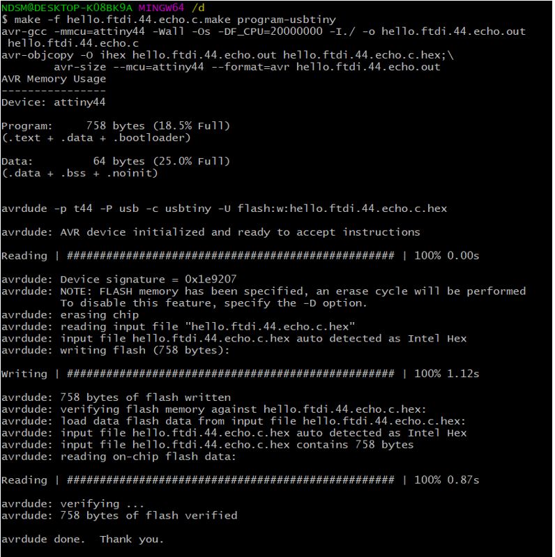
All right. The board has been successfully programmed.
But now I realize that I don’t have an FTDI cable to test it. The FTDI cable is necessary in that code to open the serial port. Coronavirus stuff …
So I’m going to try to make the Blink program in C language. I get to write this code in NotePad ++ with the help of this Programming tutorial , the datasheet of the Attiny44, and the example hello.ftdi.44.echo.c.
The LED pin on my board is PB2 (PortB, Pin 2, DDRB)
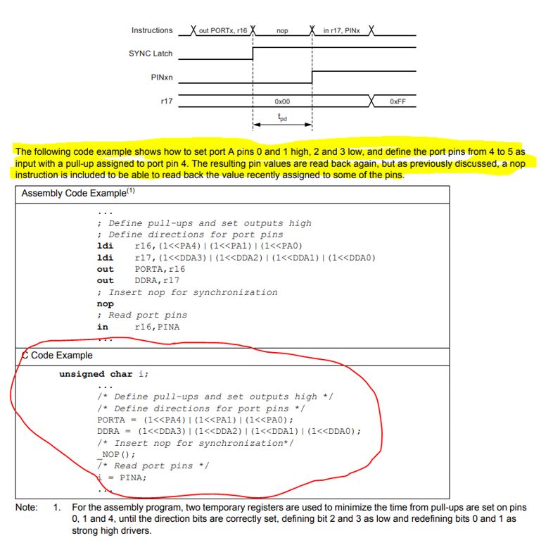
In the Datasheet I find an example of how to configure the pins as outputs / inputs.
This is how I configure the pin of my Led as output:
DDRB = (1<<PB2);
This is how I put the pin up (Led on):
PORTB |=(1<<PB2);
This is how I put the pin down (Led off):
PORTB &= ~(1<<PB2);
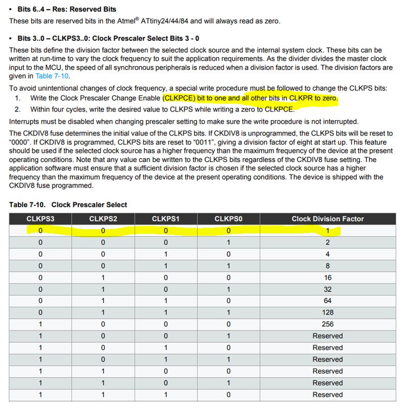
Here is how to set the clock scale, necessary in my case for the delays to work well.
CLKPR = (1 << CLKPCE);
CLKPR = (0 << CLKPS3) | (0 << CLKPS2) | (0 << CLKPS1) | (0 << CLKPS0);
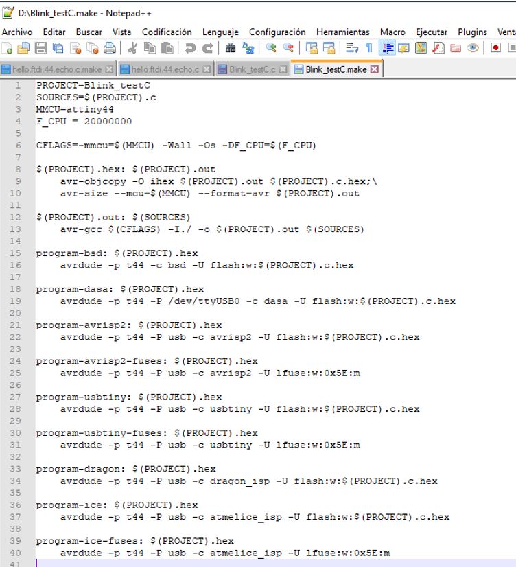
I write my code in NotePad ++:

And I also create the .make file from the hello.ftdi.44.echo.c.make file by just changing the first line with the name of my file.
And I program it with GitBash.
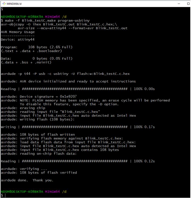
Now if I can check that it has been programmed correctly.