18. Mechanical design / Machine design
Group assignment
-
Design a machine that includes mechanism+actuation+automation.
-
Build the mechanical parts and operate it manually.
-
Actuate and automate your machine.
-
Document the group project and your individual contribution.
This assignment has been made between Adrián Torres (León), Iván González (Bilbao), Lola Ojados (Cartagena) and myself (Cartagena). Given the current situation, we have done it remotely, with Adrián being the executing hand.
You can see the complete documentation of the machine on our Group Website.
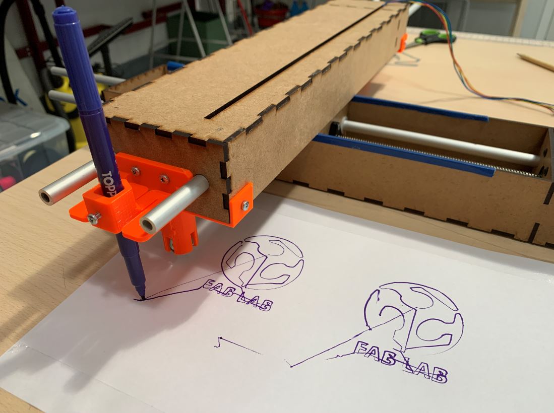
This is our machine:
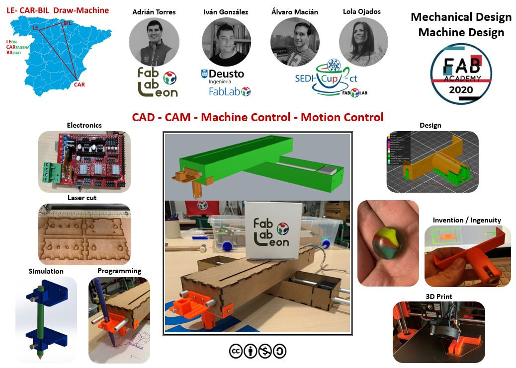
18.1. My contribution
I have been in charge of Programming the machine.
18.1.1. Machine materials
These are the electromechanical components that we have used in our machine:
- 4-wire threaded rod
We do not have information about the rod because it is recycled from another project. Based on information from similar rods we initially consider the feed to be 8mm / turn.
-
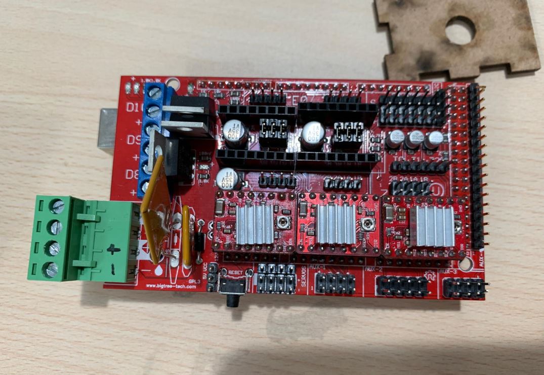
Arduino Mega 2560
-
Ramps v1.4
-
Drivers Polulu (HR4988)
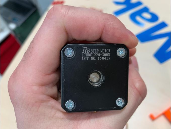
- RB step motor 17HDC1220-300N
I cannot find datasheet of this model, so I consider initially that it is similar to the Nema 17HS4401 whose characteristics are:
Type: Bipolar.
Voltage: 12V.
Current: 1.7A
1.8 degree step angle.
No. Steps: 200.
- Power supply, 12V 10A
I have done the programming tests using the material I had available:
-
Ramps v1.5
-
Drivers Polulu (HR4988)
-
HTA3D step motor 17HS4401
18.1.2. Firmware
As we have little time, we will use a firmware to control the machine.
In this link there is a list of the most used firmwares for 3D printers and CNC machines.
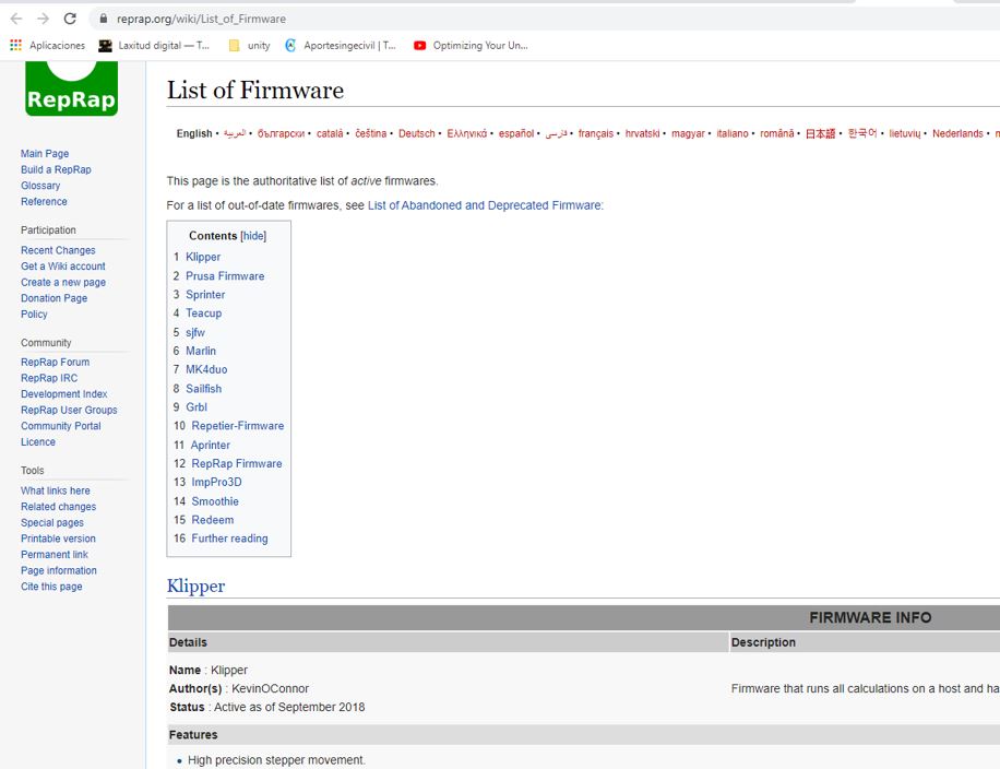
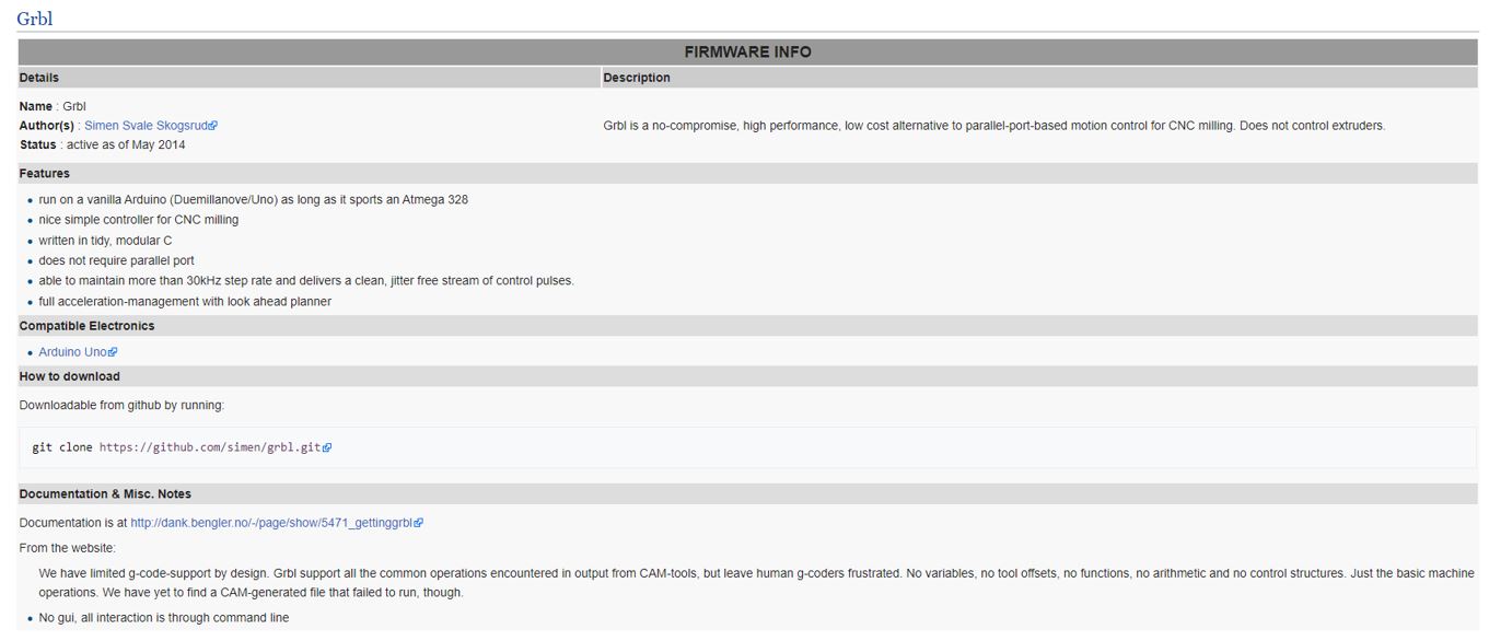
We decided to test the GRBL firmware because it is easy to configure and can be controlled using the Universal G Code Sender software.
To download the Universal G Code Sender software, click on this link. To run it you need to have JAVA installed.
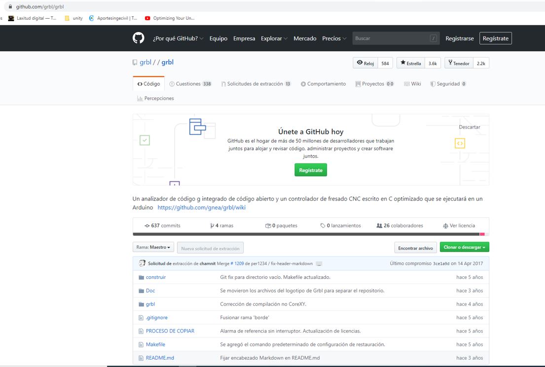
We downloaded GRBL firmware from here.
I cannot install it because it is an update of the previous version and it needs you to have the first version loaded on the arduino, so I find this link to download it.
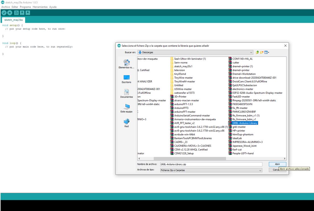
In examples is the script to load the GRBL to arduino.
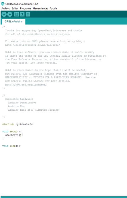
I load the script into the Arduino Mega without connecting the Ramps for security. Now I open the Universal G Code Sender to try to move the motors.
PROBLEM
We connect to the Arduino Port and in the “Machine Control” tab we try to move the motors by pressing x +, x-, y +, y-. But the motors do not move with this firmware. Maybe we have to modify the code to work with the ramps.
SOLUTION
We looked for solutions to my problem and found that there is a GRBL firmware version for Arduino Mega and Ramps. This is the link.
I load it into the Arduino without any problem.
PROBLEMS
But when Adrián and Iván try to load it, appears an compilation error. Cannot find the system.h file.
SOLUTION
Finally, Adrián tries another computer (Nuria’s super computer) and manages to load the firmware on the Arduino.
We connect the Ramps (with the drivers and motors connected) to the Arduino and connect the power supply.
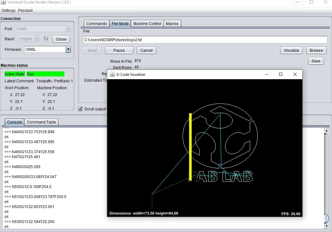
18.1.2. Universal Gcode Sender
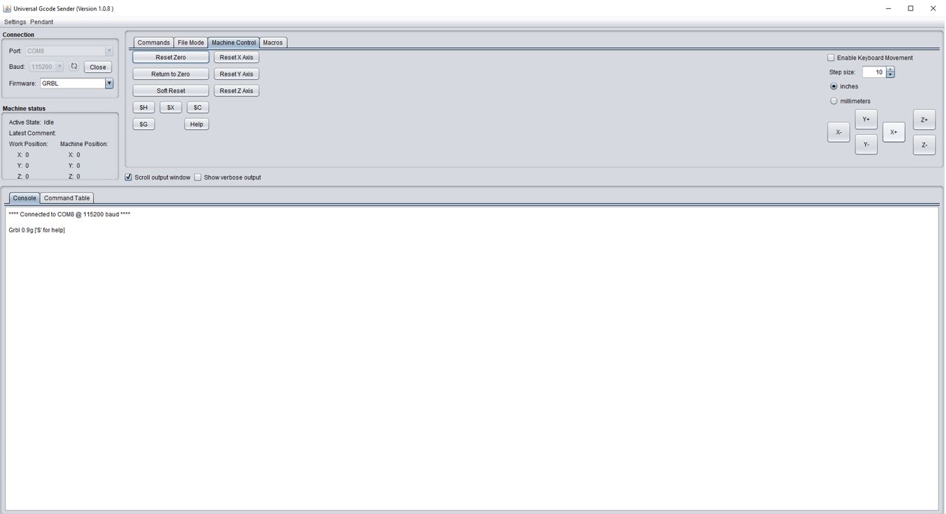
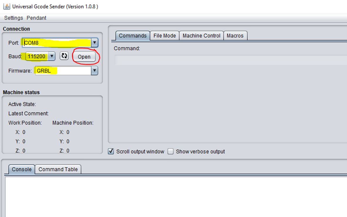
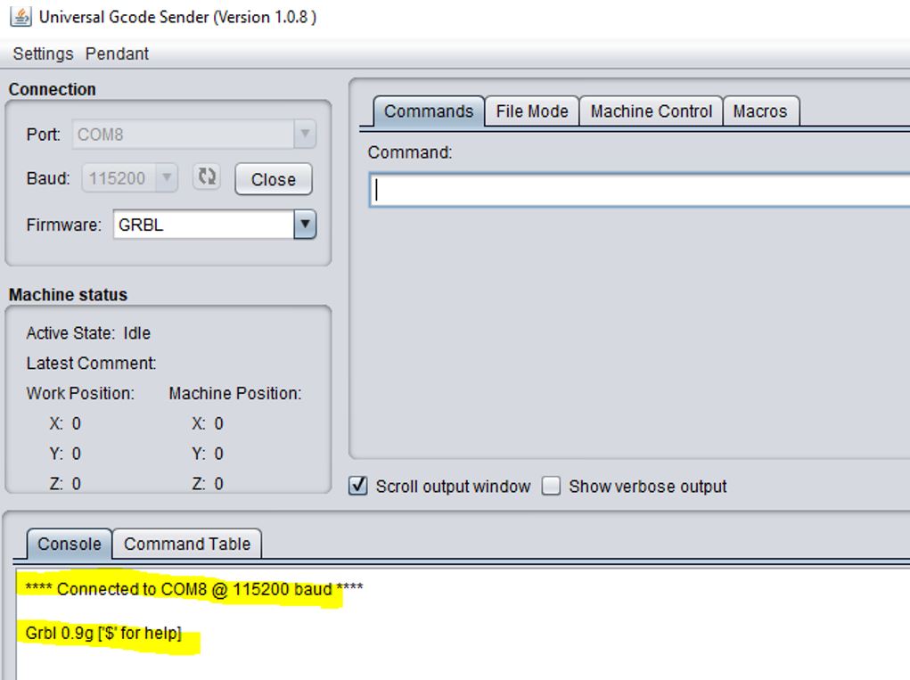
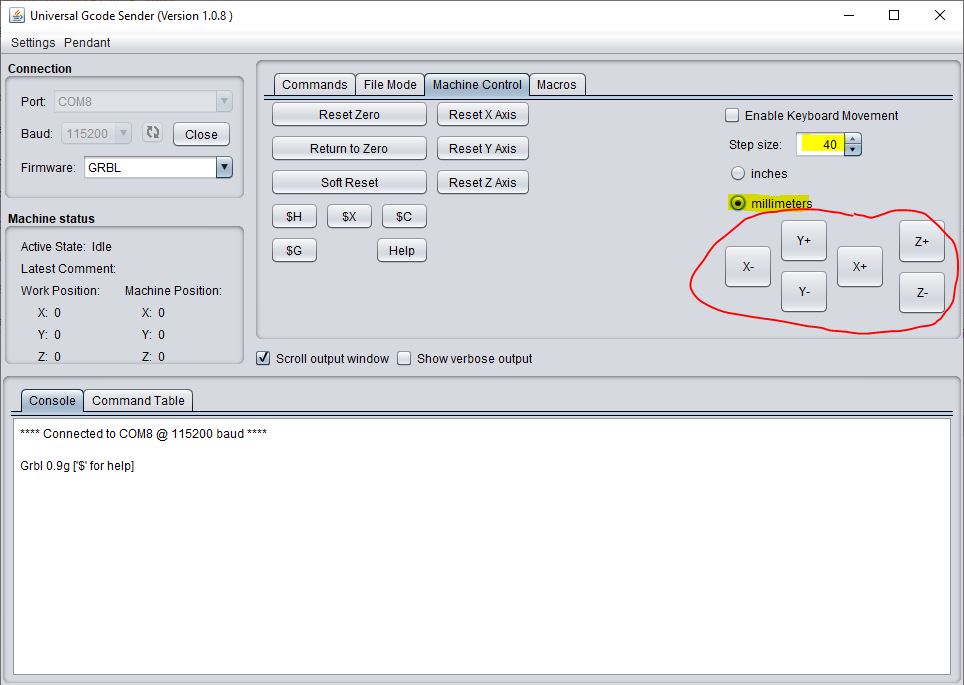
Now we open the Universal Gcode Sender. And we select the Arduino port, 115200 baud and GRBL. We click on “Open” and the software connects to the arduino.
To do a first test, in the “Machine Control” tab select “Step Size” = 10, “millimeters” and click the x +, x-, y +, y-, z + and z- buttons to move the motors.
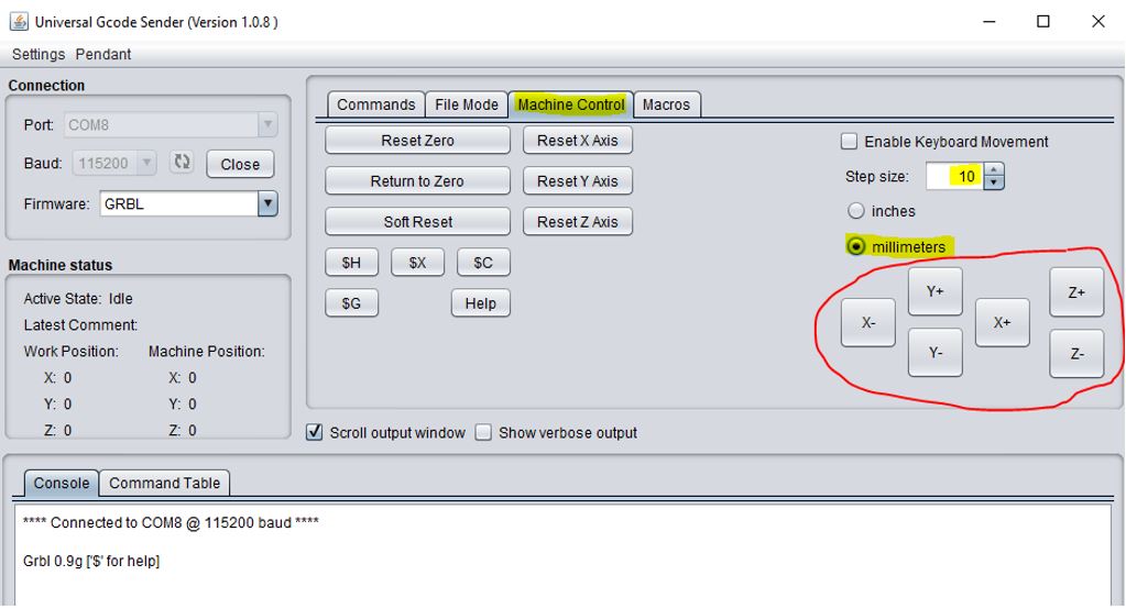
Now the engines work.
The next step is to correctly configure the firmware so that the car moves the distance that we say. In the “Commands” tab, we write “$$” to see the parameters.
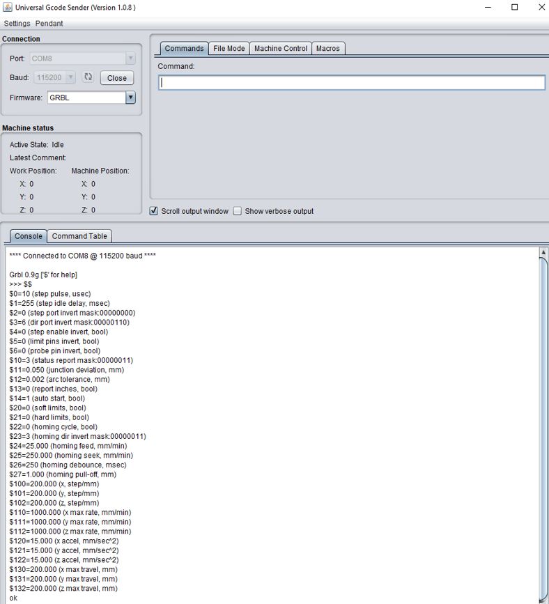
The relationship between motor steps and displacement in millimeters (steps/mm) of each motor are the parameters 100, 101 and 102.
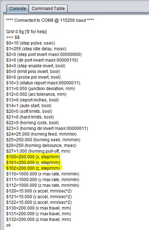
CAs we do not have the datasheet of the threaded rod and the motors, we have initially considered the following parameters:
-
Threaded rod feed = 8mm / turn.
-
Stepper feed = 200 steps/ turn.
So 200/8 = 25 steps/mm
We change the parameters writing in the console of the “Commands” tab:
$100=25

$101=25

$102=25
We tried moving the carriage 40mm using the buttons on the “Machine Control” tab but the carriage barely moved.
Rod and motor parameters are not correct, so we have to test values to correct it.
We tried to configure to 250 steps / mm
$100=250

$101=250

$102=250
But the carriage moves 24mm instead of 40mm. So we make a cross multiply and we get 416 steps / mm.**
(250x40)/24=416
$100=416

$101=416

$102=416
Now the carriage moves what we say.
18.1.3. Sending a Gcode
Universal Gcode Sender software allows you to use a gcode to move the machine.
We tried using Mods to generate a gcode and loaded it. But it doesn’t work properly. In addition we realize that we have interchanged the z and y axis. We changed them on the ramps to fix it.
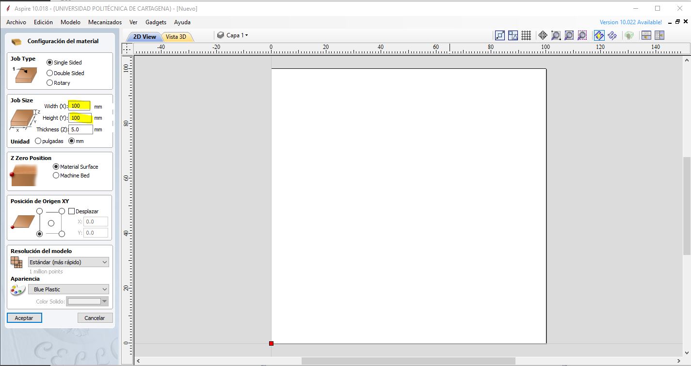
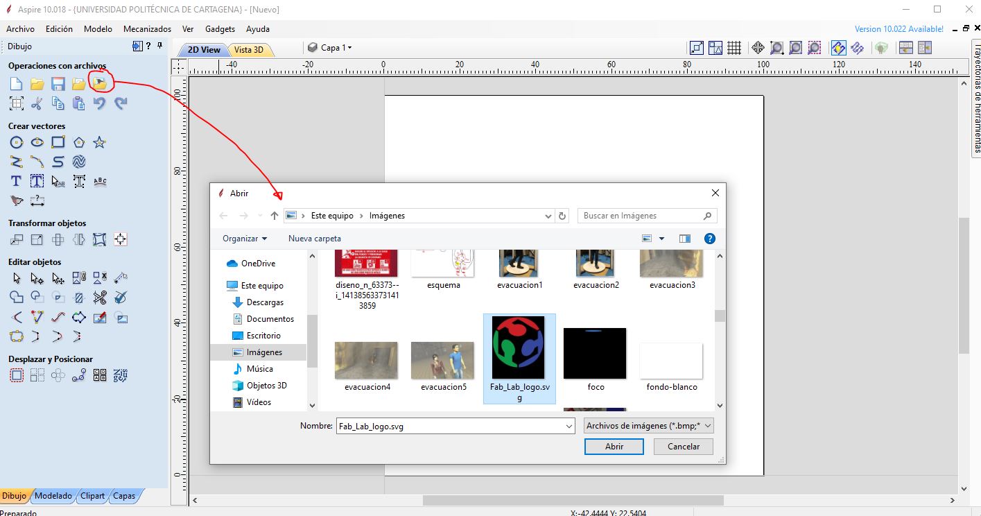
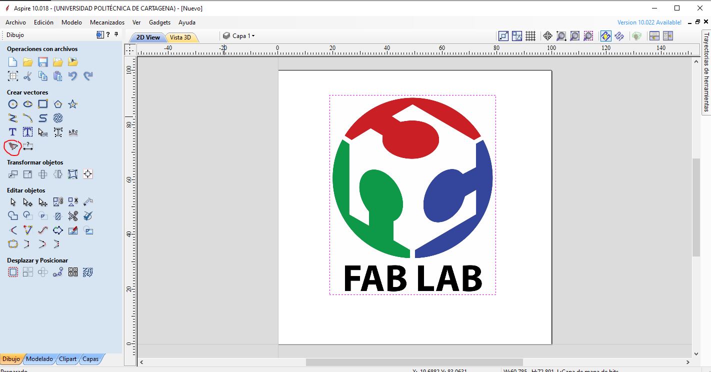
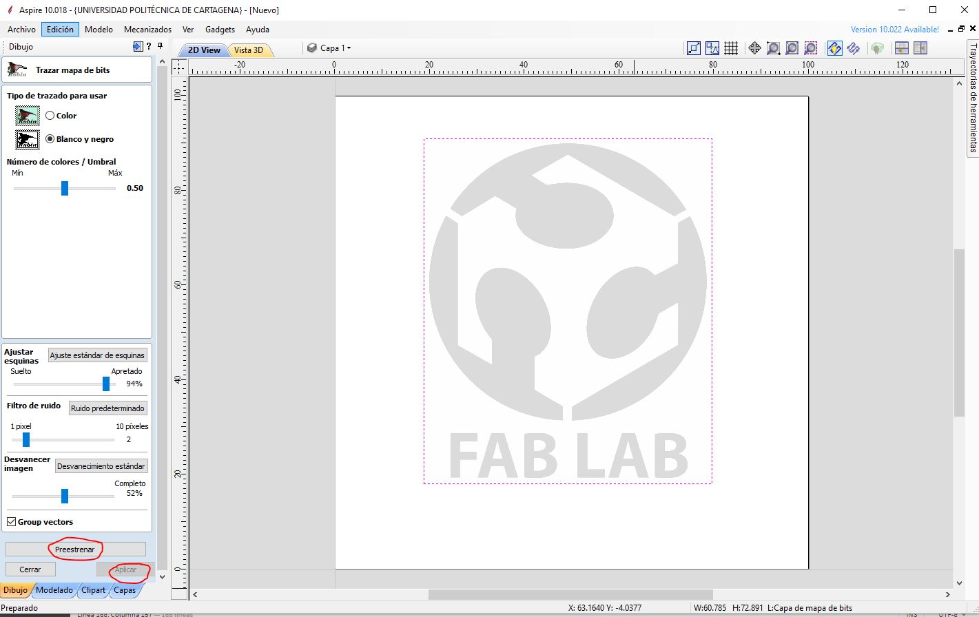
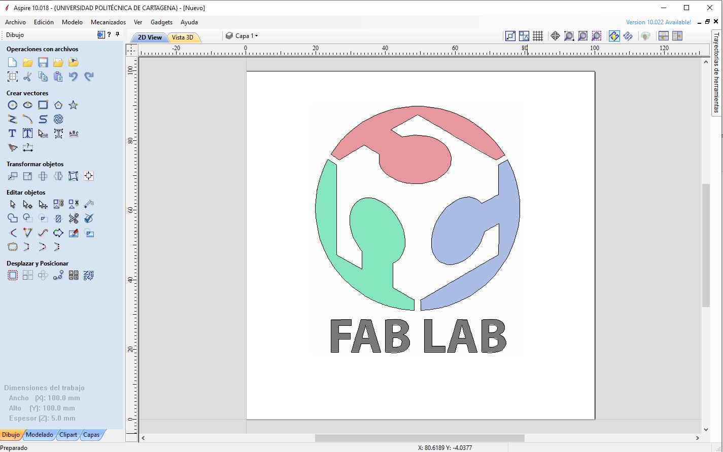
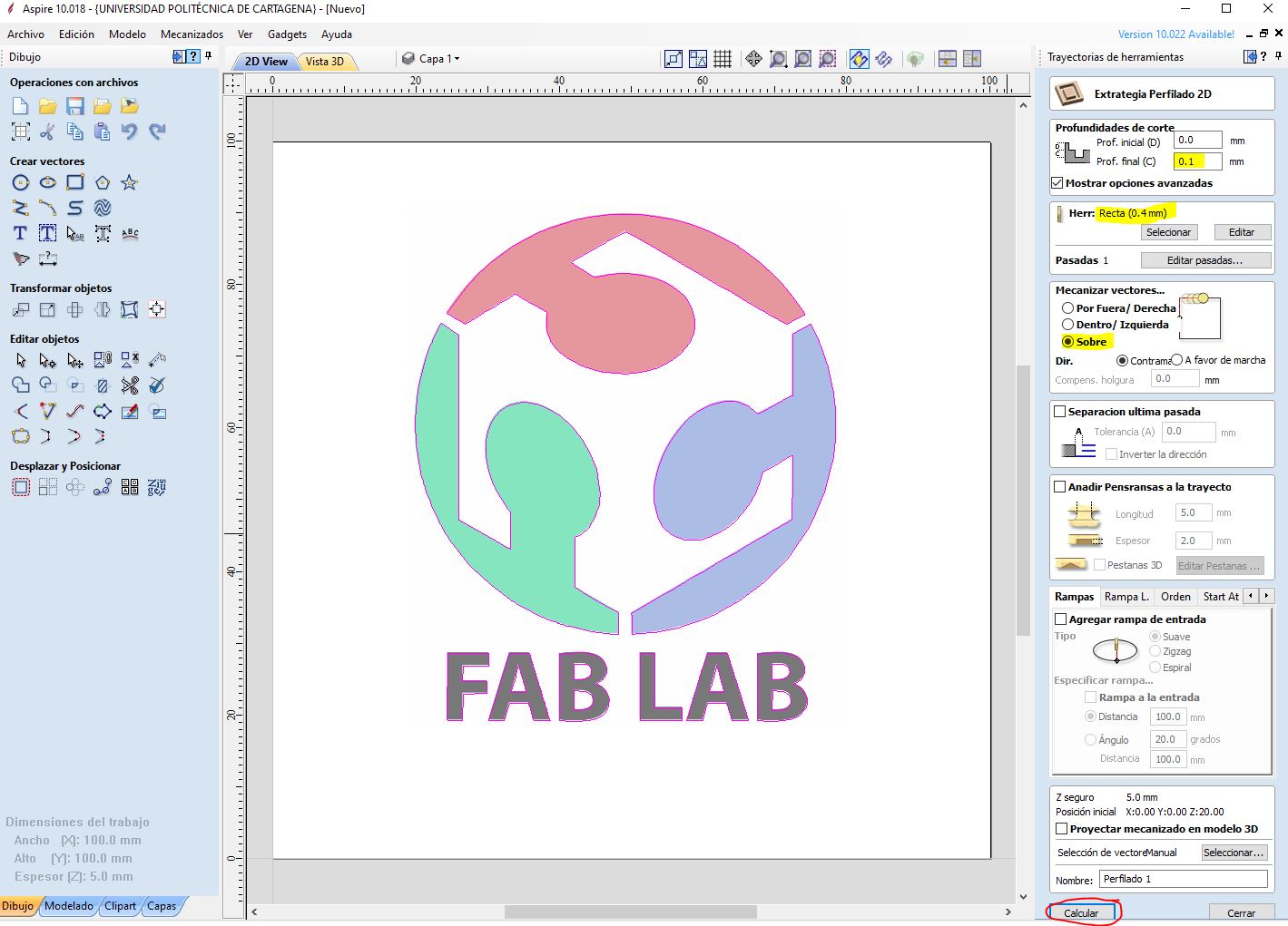
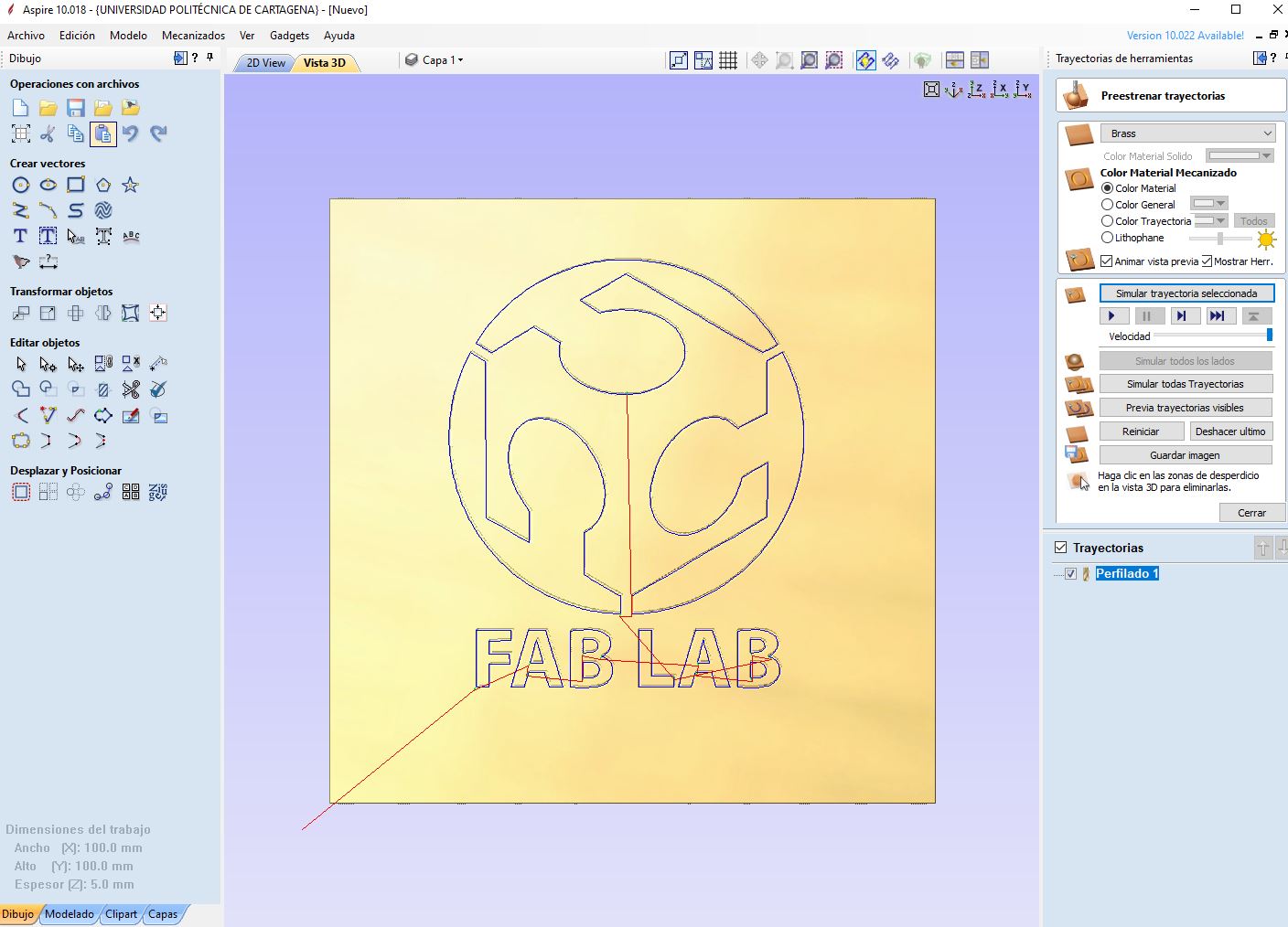
But that gcode keeps doing weird things. So I use Cut2D / Aspire software, which I normally use to generate gcodes for my circuit mill.
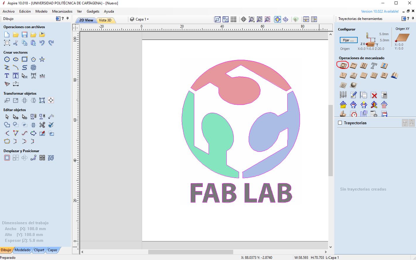
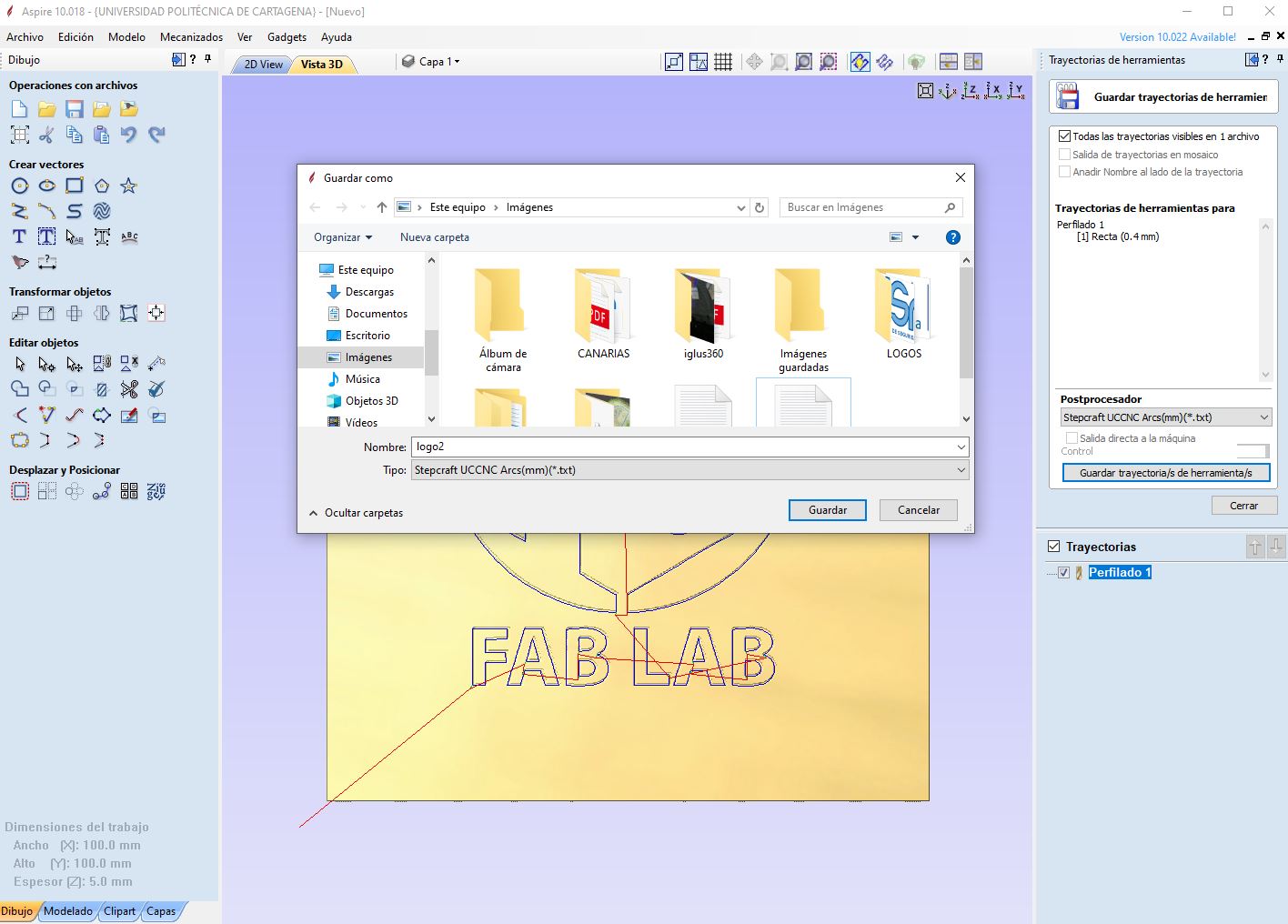
Finally we open this gcode in Universal Gcode Sender and it works correctly.