6. 3D Scanning and printing
-
Group assignment
-
Test the design rules for your printer(s).
-
Document your work and explain what are the limits of your printer(s) (in a group or individually).
-
-
Individual assignment:
-
Design and 3D print an object (small, few cm3, limited by printer time) that could not be easily made subtractively.
-
3D scan an object, try to prepare it for printing (and optionally print it).
-
6.A. Group Assignment
The Group Assignment page is at the following link.
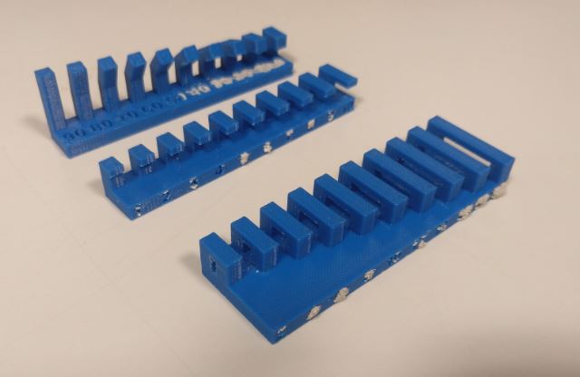
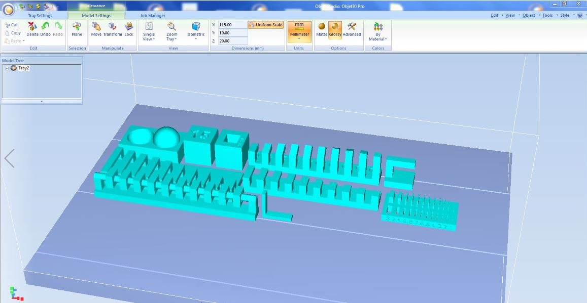
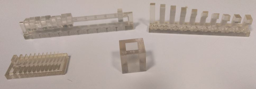
Test the design rules for your 3D printers.
To perform the tests we have used the Neil models.
Our 3D printers are:
-
Dimension bst 1200es.
-
Ender 3 Pro.
-
Object30 Pro.
6.A.1. Dimension bst 1200es
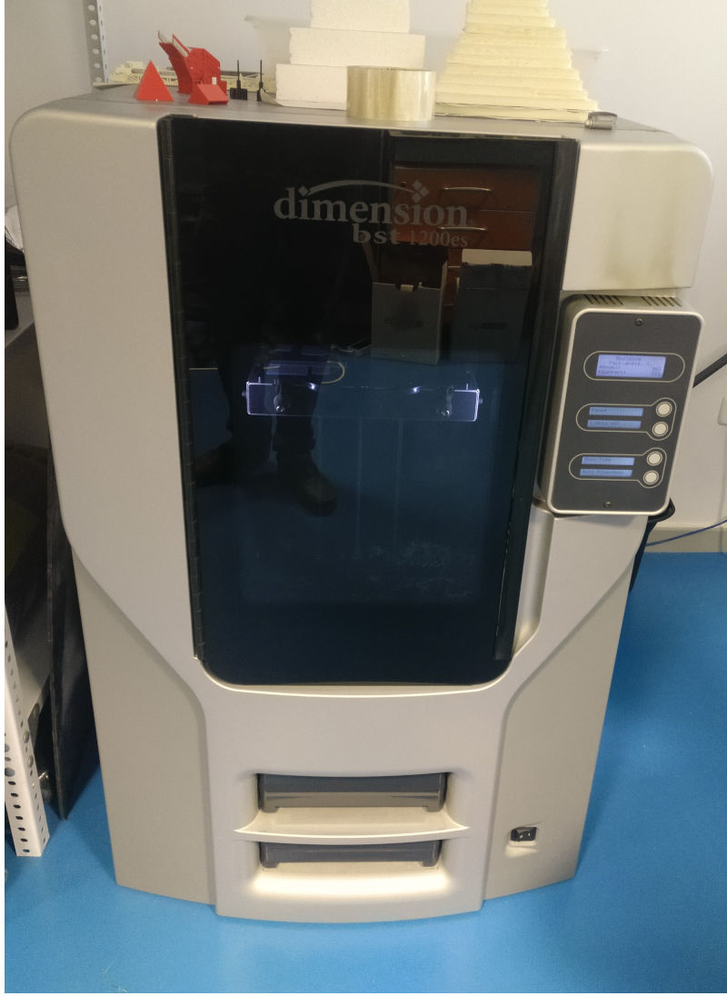
6.A.1.1. Characteristics
This printer is of the FDM type.
-
Modelling material: ABSplus in ivory, white, black, red, olive green, nectarine, fluorescent yellow, blue or gray.
-
Support material: Breakaway Support Technology.
-
Measures: 254 x 254 x 305 mm.
-
Layer thickness: 0.254 mm (0.010 in.) Or 0.330 mm (0.013 in.) Of ABSplus support and modelling material accurately deposited.
ASB plus has a different composition than the standard ABS, improving its mechanical properties.
6.A.1.2. Software and print settings
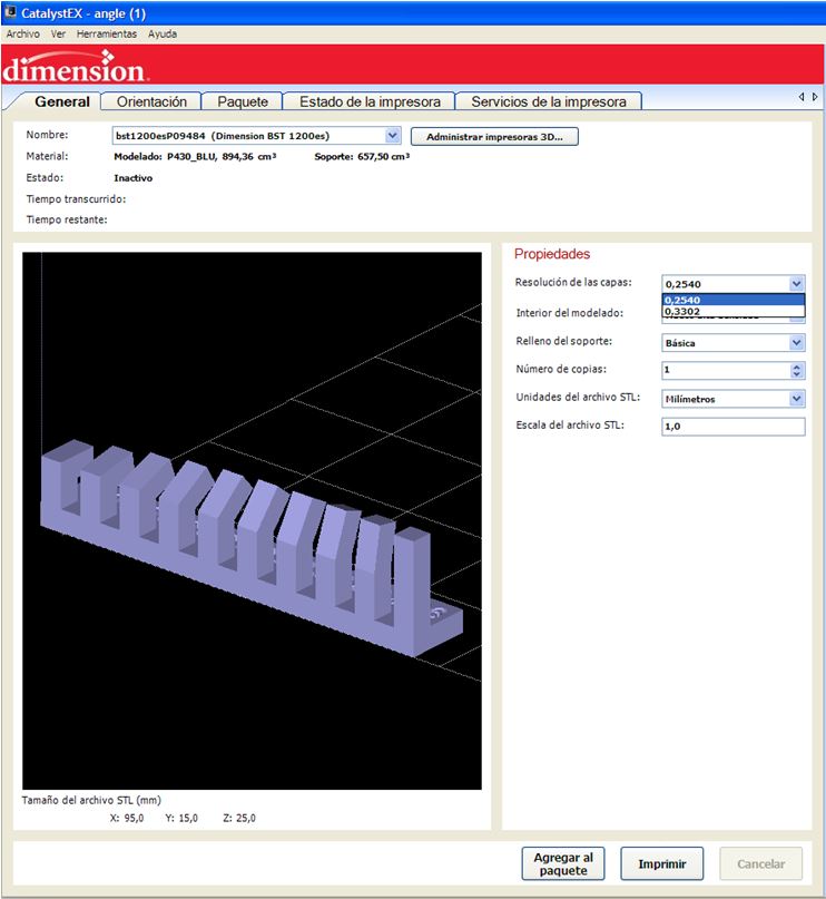
This 3d printer necessarily uses its own software, CatalystEX.
We configure the layer resolution. We select 0.2540 mm to obtain a better finish.
In the Interior option of the model we configure the filling density of the model. We select the “Low density gap” option to speed up printing time.
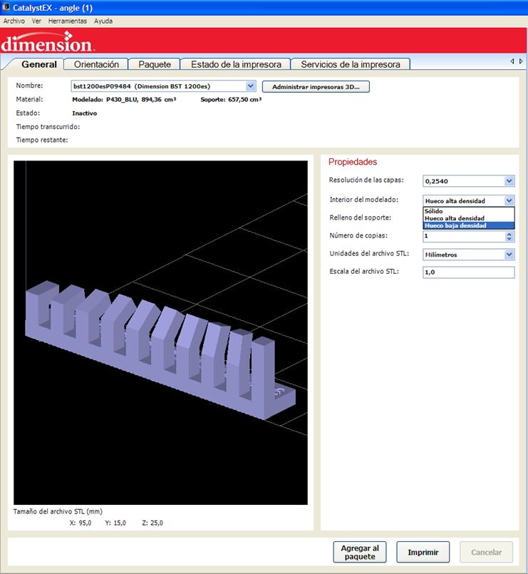
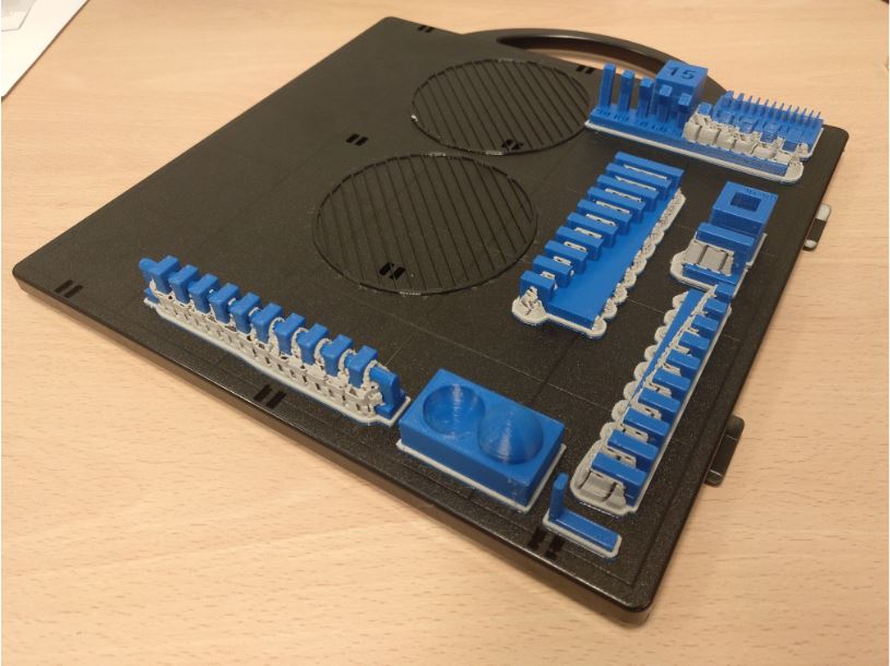
Support padding configuration. Always print with support material. We select the “Separation” option because it is the one that uses less support and it is assumed that it will be easier to remove it.
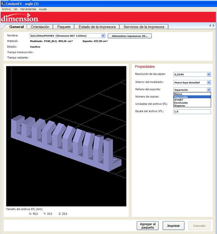
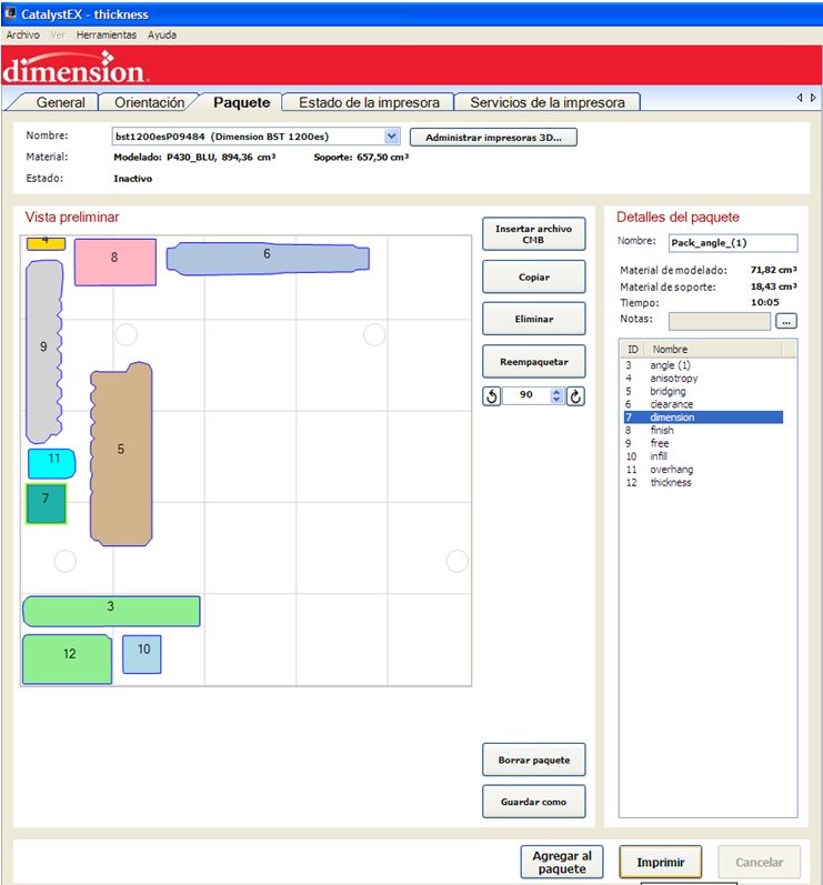
The pieces must be distributed in the printing tray without covering the circles (targets) which the machine uses as a reference. The trays are expensive, so we reuse them until there is no gap left unused (on the surface that has occupied a printed piece can no longer be reprinted). Tetris moment.
6.A.1.3. Results
-
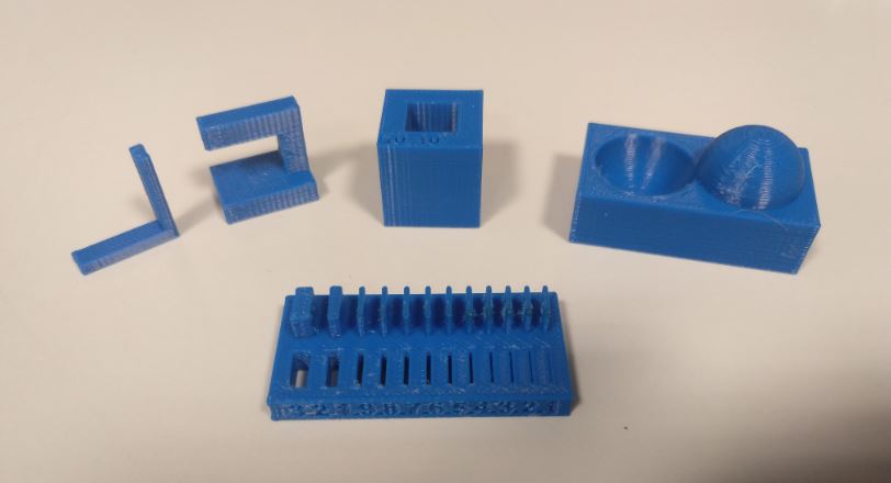
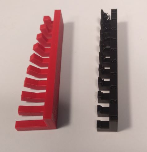
The surface finish looks smooth.
-
The bridges and overhangs are perfect since it always uses support material.
-
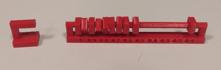
The minimum wall thickness is 1 mm, if in the design the thickness is smaller it will also print it at 1 mm. For slots if it reaches 0.1mm.
-
The difference between the actual and design thickness is + 0.1mm for wall and -0.1mm for holes.
-
The support material costs a lot to remove in narrow spaces. So it is not recommended for such parts. It must be taken into account in the design.
-
Vertical surfaces break more easily than horizontal surfaces under stress. Although it holds a lot because it is ABSplus.
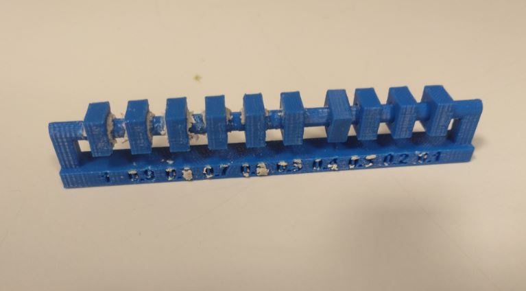
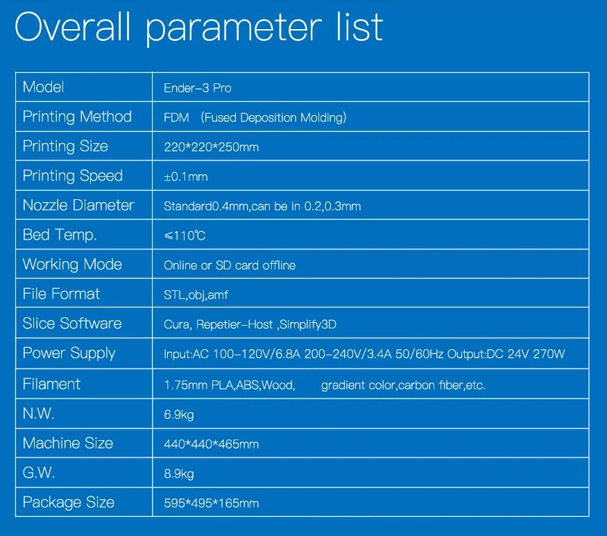
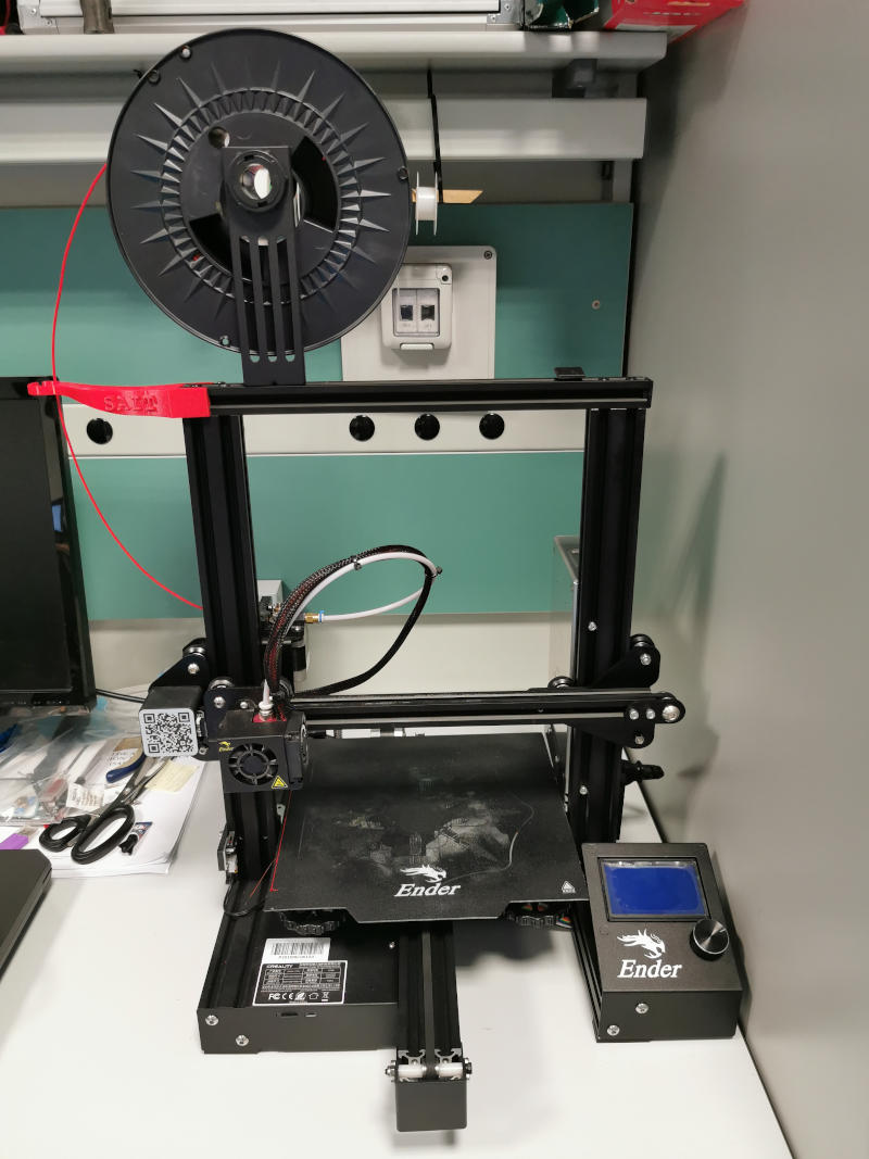
6.A.2. Ender 3 Pro
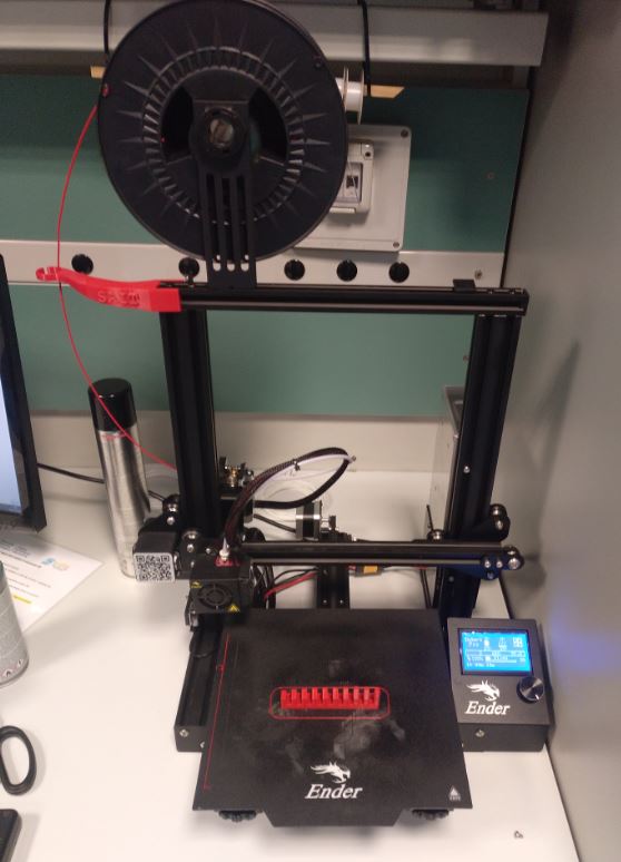
6.A.2.1. Characteristics
This printer is of the FDM type.
6.A.2.2. Software and print settings
To use this printer we use Ultimaker Cura , free software. We use the 0.4 mm diameter nozzle.
We configure on the one hand the pieces without support material and on the other hand the pieces with support material.
6.A.2.3. Results
-
The surface finish looks smooth.
-
The bridges are perfect.
-
The lower part of the overhangs of more than 3 mm has threads that have come loose. To get a better finish you need support material.
-
The angles look perfect until 20 degrees of inclination.
-
The minimum wall thickness is 0.5 mm. For slots if it reaches 0.1mm.
-
The difference between the actual and design thickness is + 0.1mm for wall and -0.1mm for holes.
-
The minimum clearance for joints is 0.2 mm.
-
Vertical surfaces break more easily than horizontal surfaces under stress.
6.A.3. Object 30 Pro
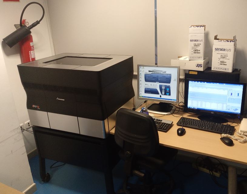
6.A.3.1. Characteristics
This printer is of the Polyjet type.
6.A.3.2. Software and print settings
This 3d printer necessarily uses its own software, Object Studio.
It has almost no parameters that can be configured. Always add support material. We can only choose the surface finish (Gloss or matt).
For the tests we have used VeroClear for the model material and SUP705 for support material.
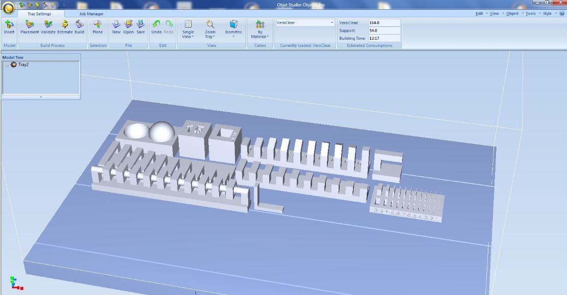
6.A.3.3. Results
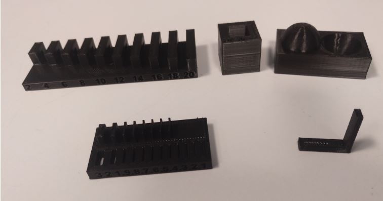
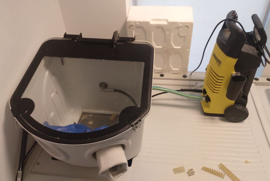
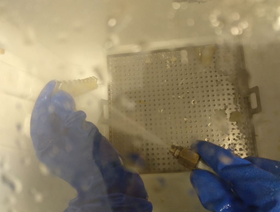
To remove the support material a bucket with pressurized water jet is used.
-
The surface finish is perfect.
-
All geometries are perfect.
-
The difference between the actual and design thickness is + 0.05mm for wall and -0.05mm for holes.
-
The minimum wall thickness is 0.1 mm. For slots if it reaches 0.2mm.
-
The minimum clearance for joints is 0.2 mm.
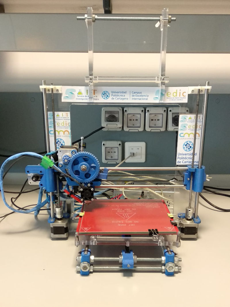
6.B. Individual Assignment
6.B.1. Design and 3D print an object
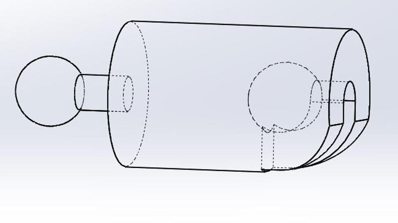
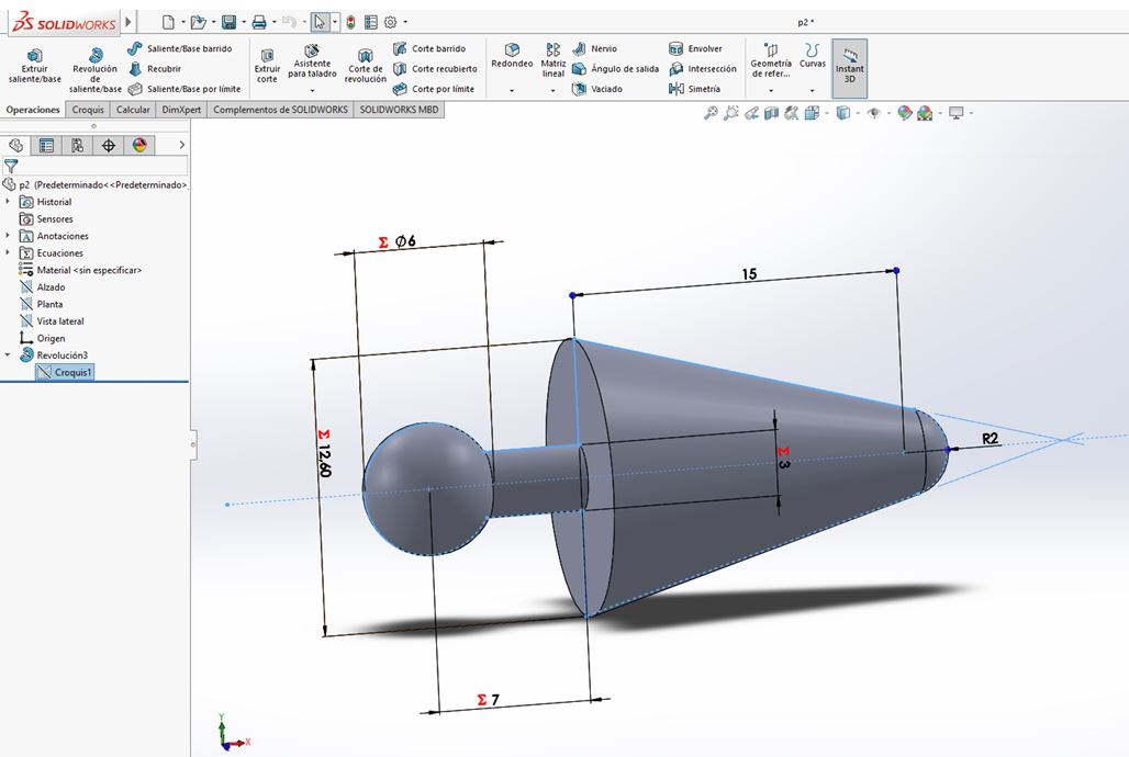
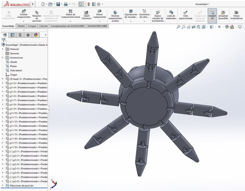
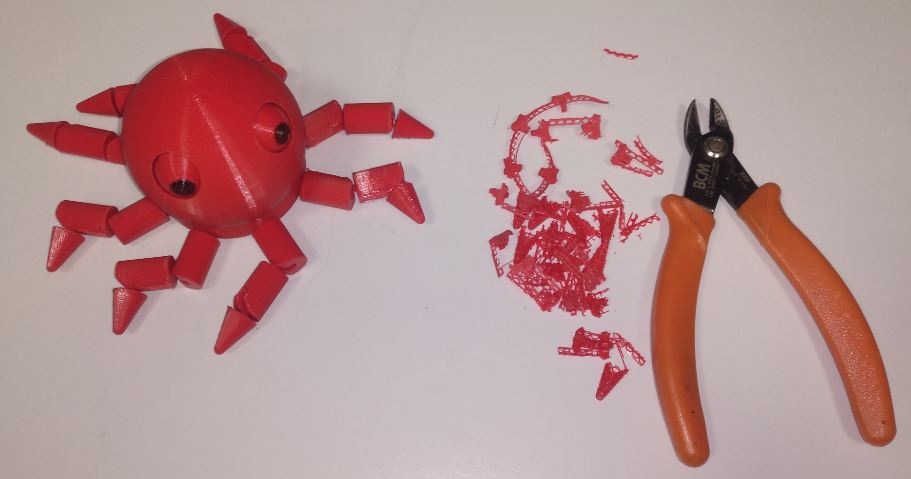
My idea has been to design and print articulated doll, an octopus.
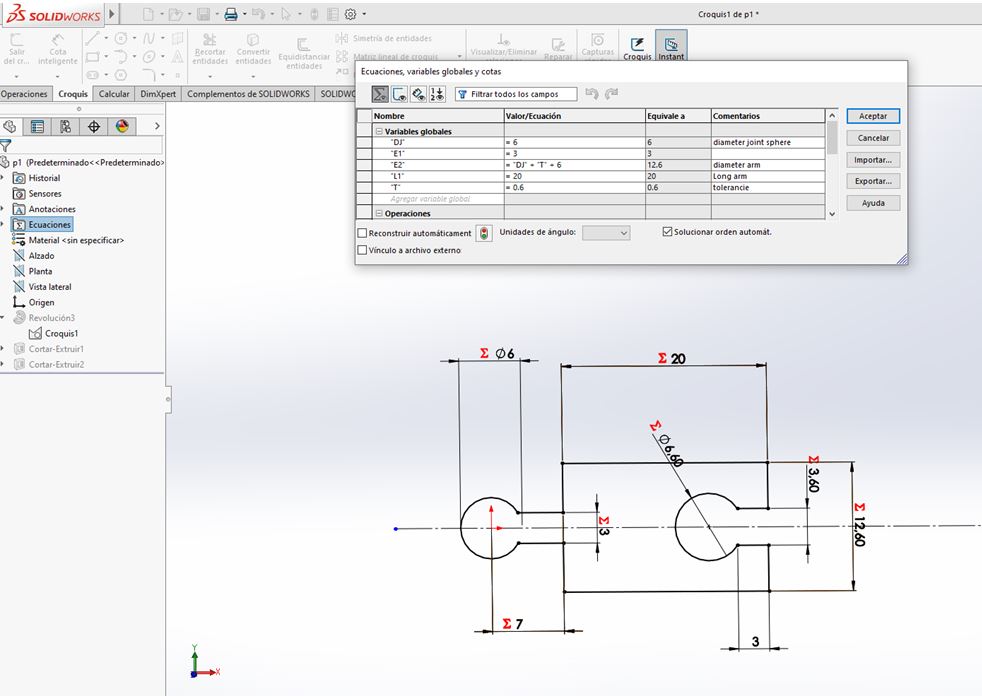
I have used Solidworks to design the parts that compose it. And then I have joined them in an assembly by positioning them so that the support material was easy to remove. I have made the joints with a clearance equal to 0.6mm.
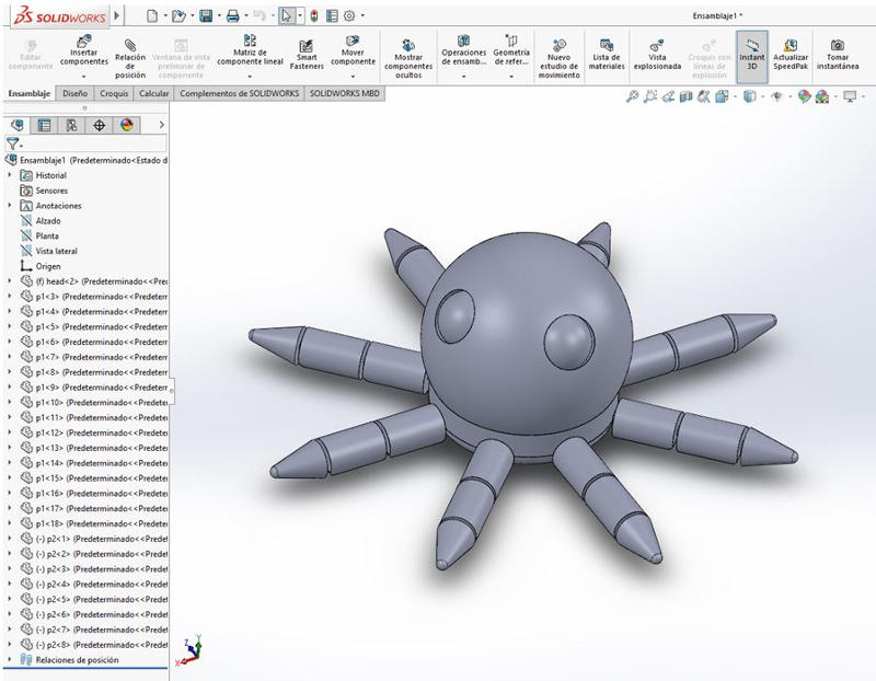
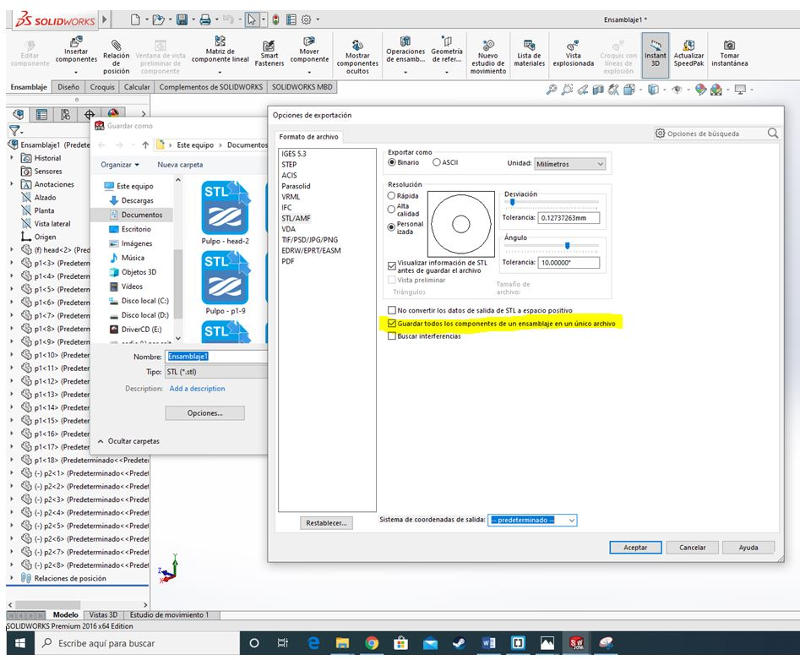
Important!!! I have finally saved the assembly as STL, but in the advanced options I have marked “Save all components of an assembly as a single file” so that they maintain the position when importing them into Cura.
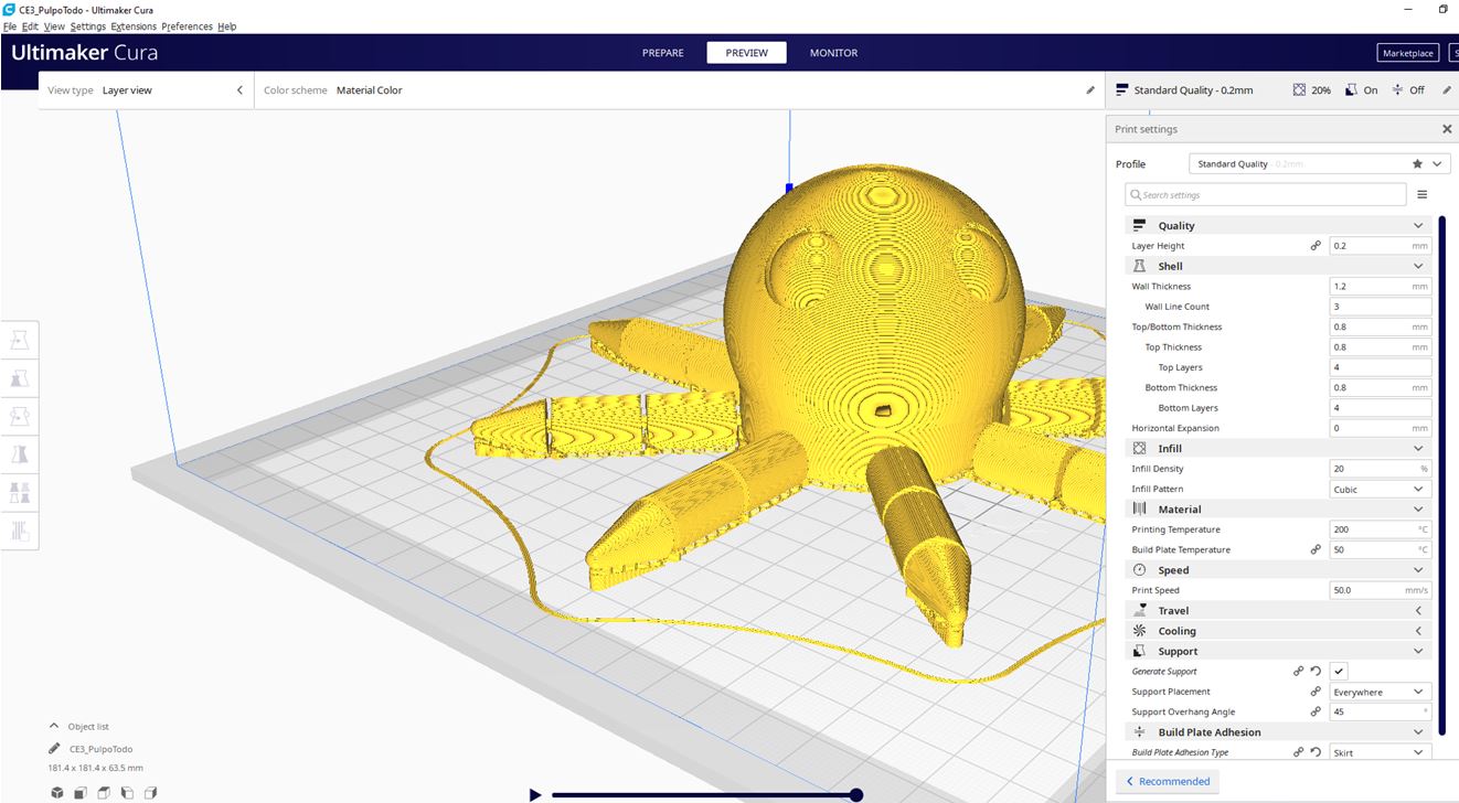
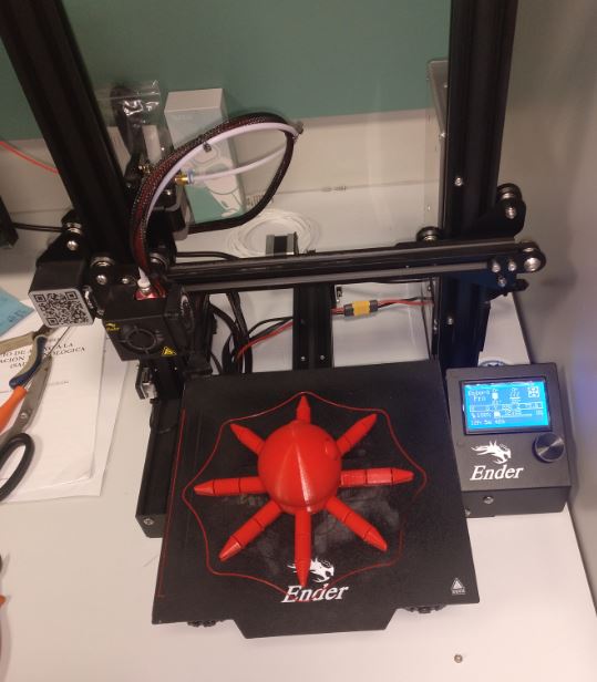
I’m going to print it with the Ender 3 Pro 3D printer. Using PLA and 0.4mm diameter nozzle. So I use Ultimaker Cura to prepare the print. It takes 12 hours.
- Video of my octopus
- Archive to print of my octopus
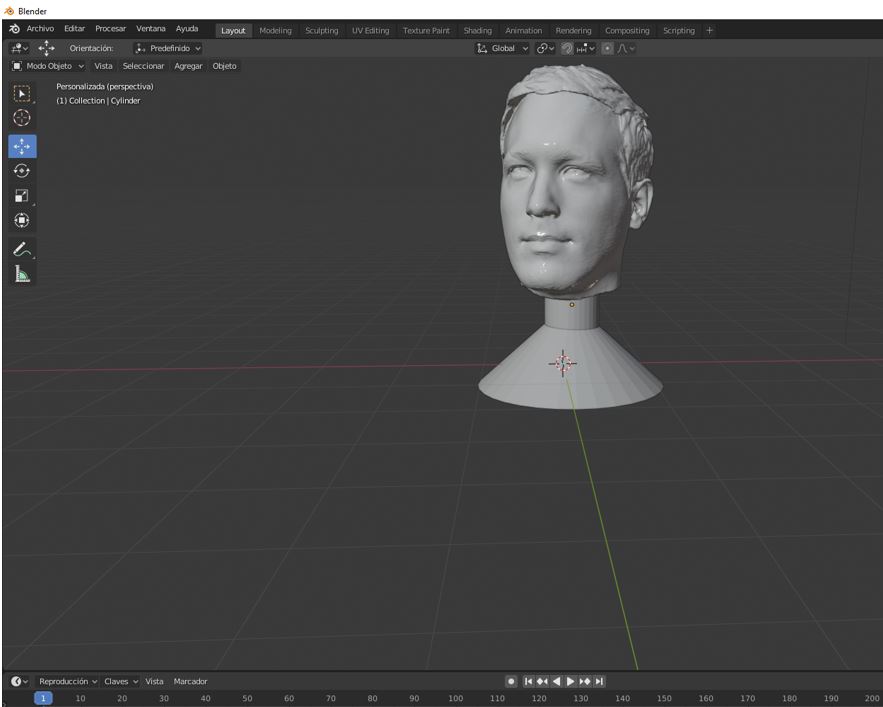
6.B.2. 3D scan an object, try to prepare it for printing
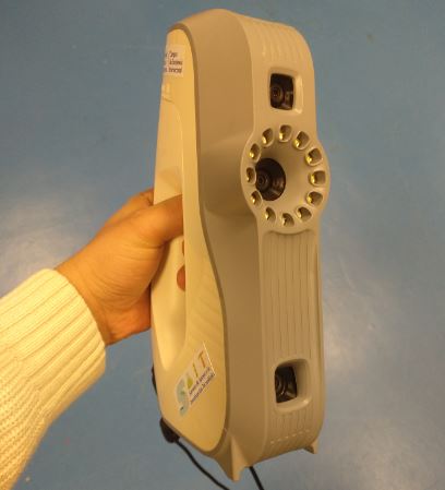
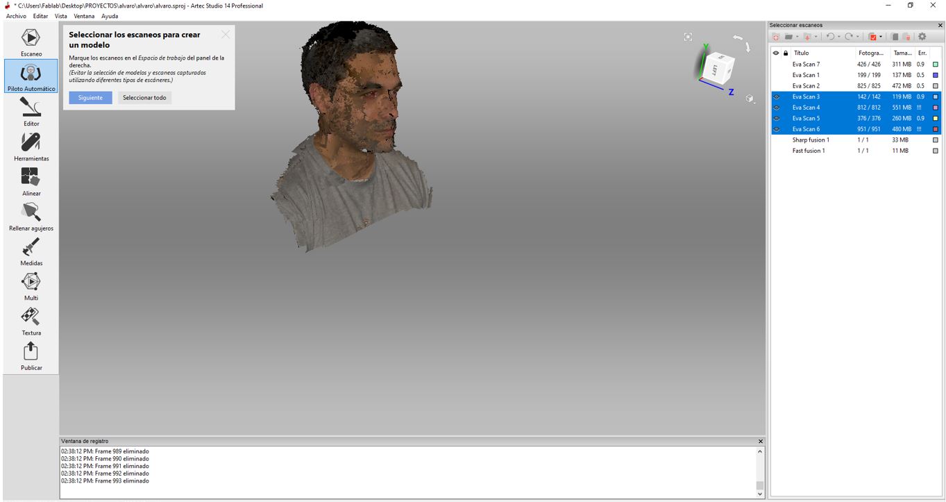
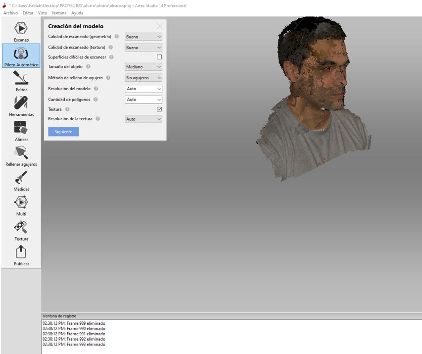
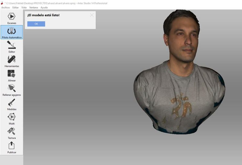
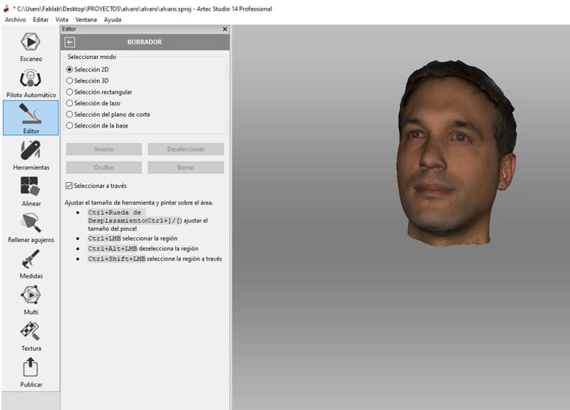
I’m going to scan my head to make a mini bust. For this I used the Artec Eva 3D scanner. This 3D structured light scanner is ideal for making a fast, accurate and textured 3D model of a medium-sized object.
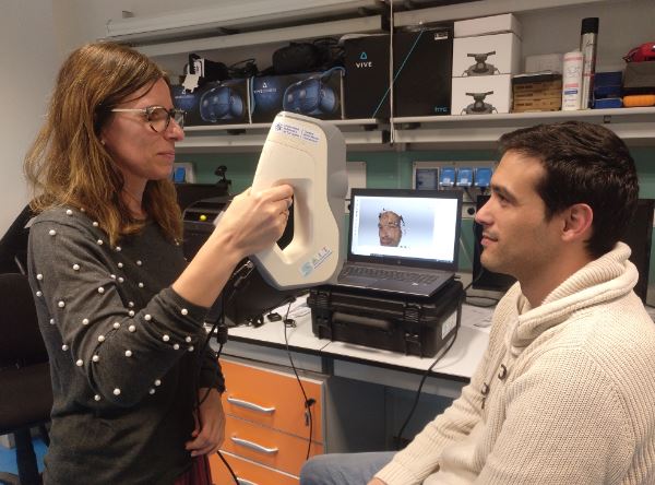
It is used with its Artec Studio software, which makes scanning easier and has post-processing tools to clean and retouch the mesh. To scan my head I need the help of my partner Lola. I had to put talcum powder in my hair to facilitate scanning, since my hair is black and shiny …
- Deleting points cloud areas.
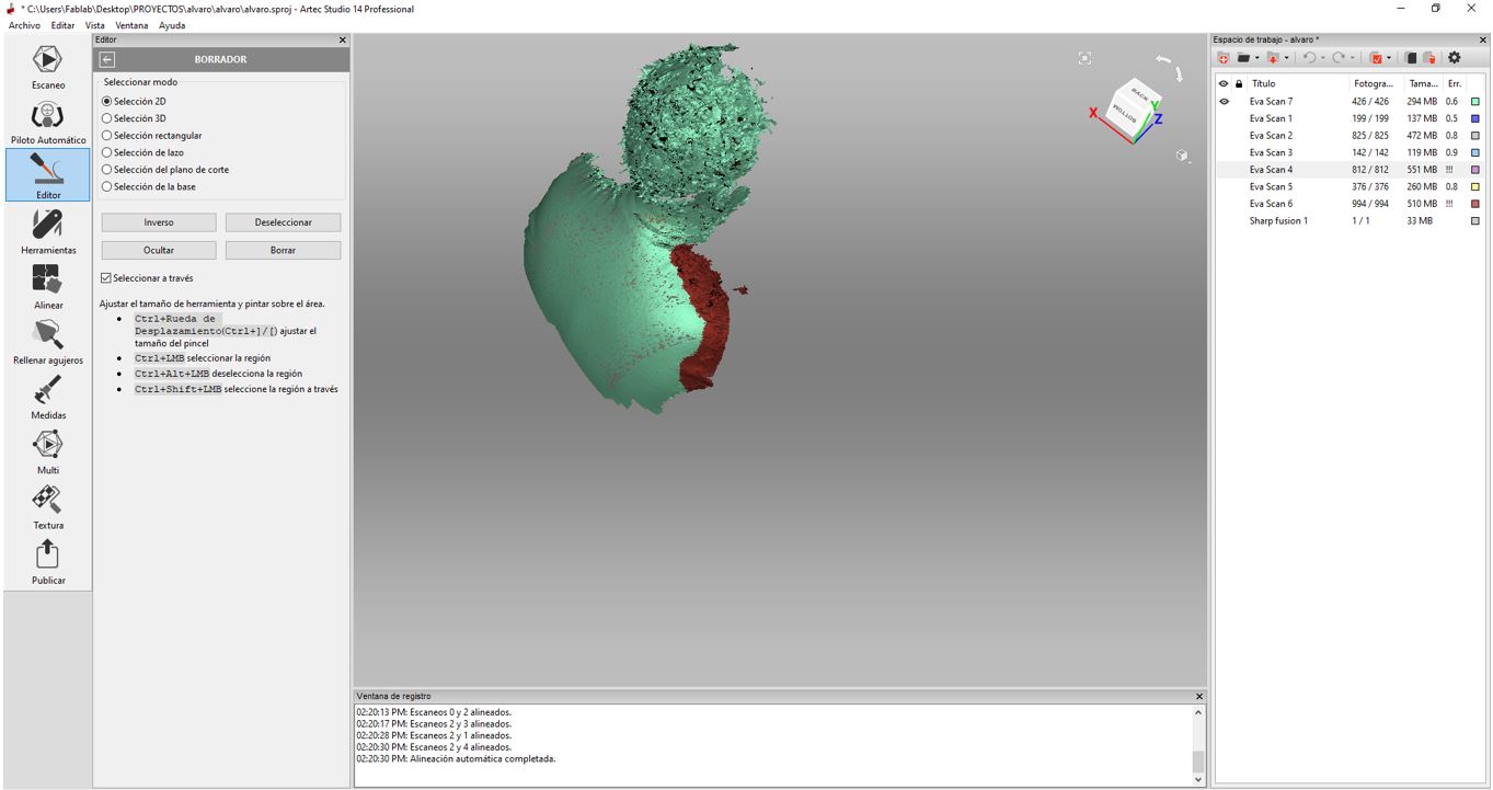
- Using the autopilot to merge the clouds of captured points.
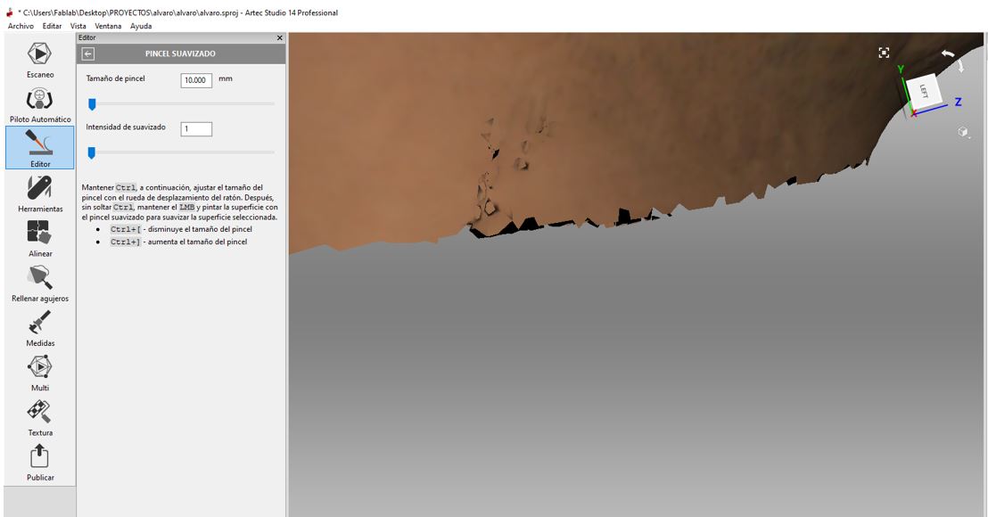
Post-Processing
- Removal of parts of the model with the “Eraser” tool.
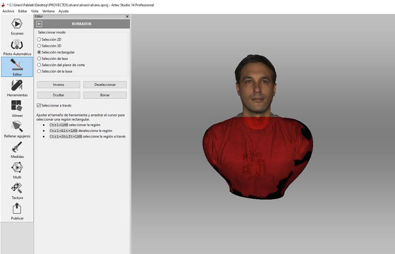
- Cover the holes with the “Fill holes” tool.
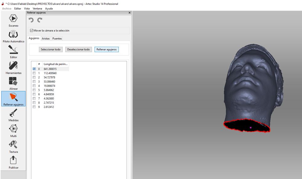
- Smooth mesh errors with the “Smoothing Brush” tool.
- And finally I get the optimized texture in case I get to use it for the next video game …
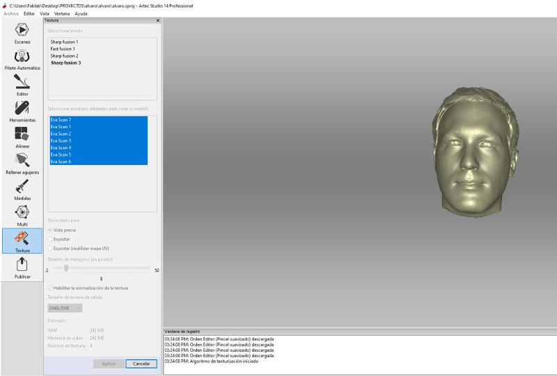
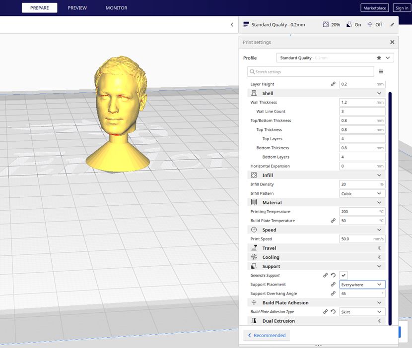
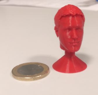
After retouching the mesh export the model in STL and OBJ. In Blender I made a stand and printed with Ultimaker Cura on the Ender 3 Pro 3D printer.
They’re going to freak out the next time I play a board game …
6.C. EXTRA ASSIGNMENT
(This part has been developed by my partner Lola)
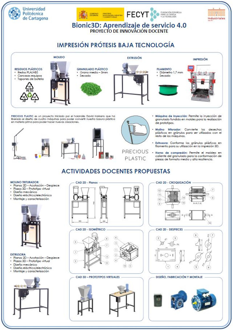
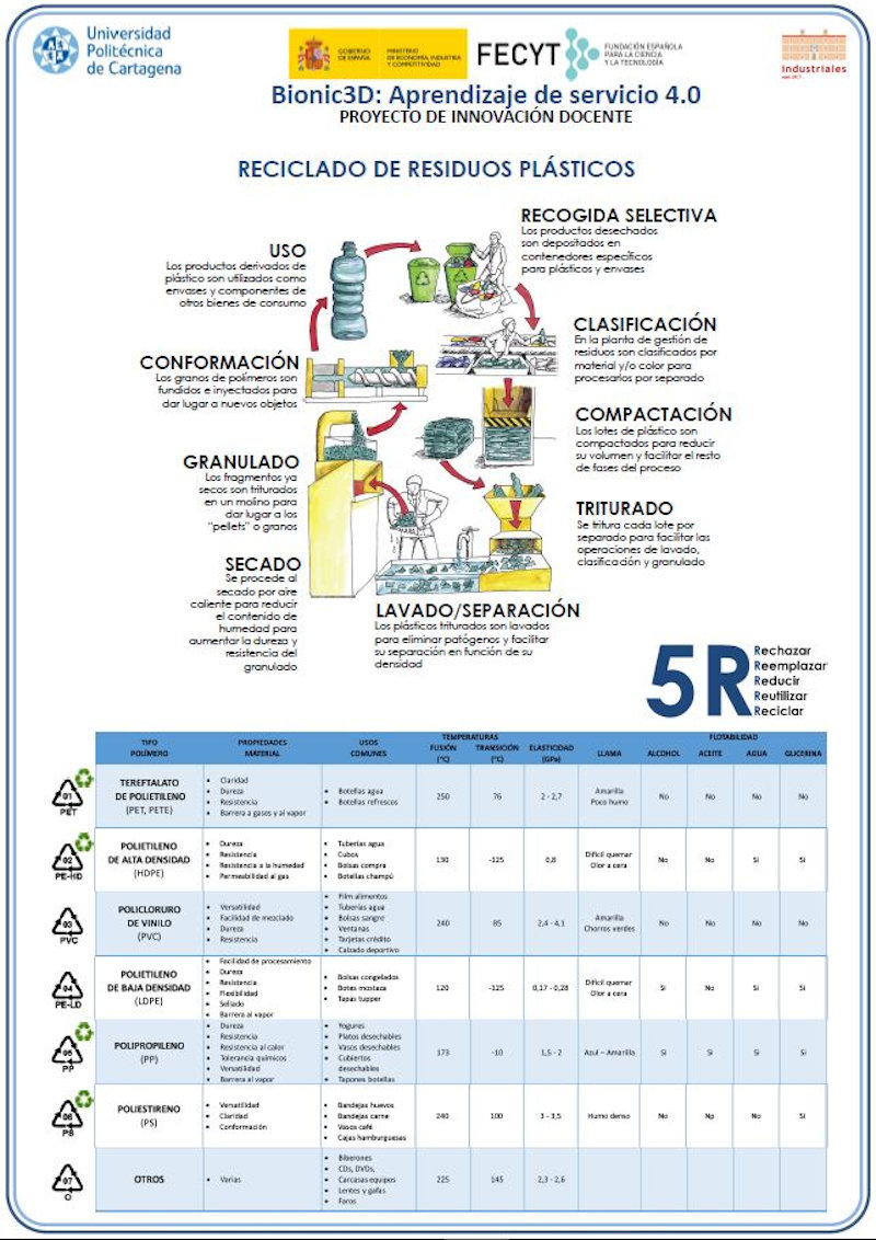
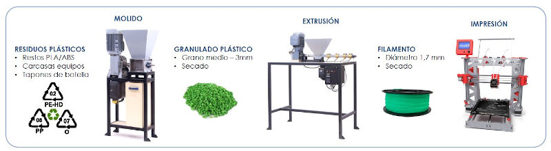
6.C.1. Recycled materials for 3D Printing
The first 3D printing machine in the SEDIC is a Dimension bst 1200es, of FDM technology, and the material used is ABSplus.
This machine has a base where parts are printed that is disposable.
It is the disposable fungible base:
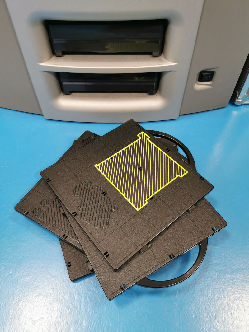
When buying the machine we did not know that the manufacturer was not responsible for removing this base or tray, they were times when sustainability was not taken into account.
But I thought it was a great waste not to reuse these bases and decided to do something with them.
In our own laboratories I did material composition analysis and wow!!
It is ABS similar to the filament used for printing.
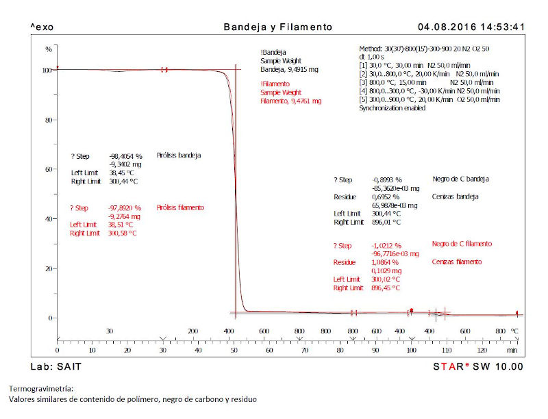
The red curve is that of the filament composition of the manufacturer who uses the printing machine, and the black curve is that of the composition of the disposable bases.
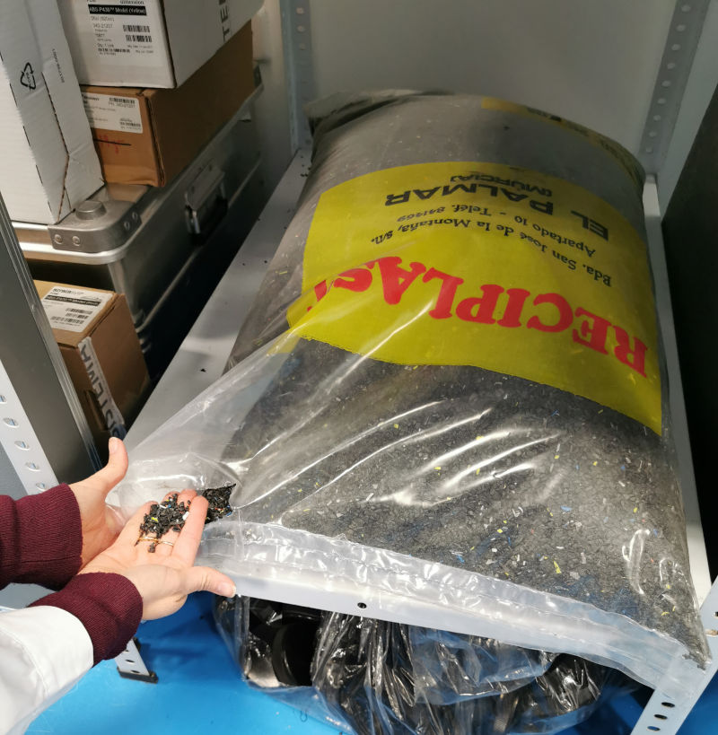
So I sent to crush the bases that I was storing for a long time so as not to throw them away with the rest of plastics.
Now I am assembling my own plastic mill.
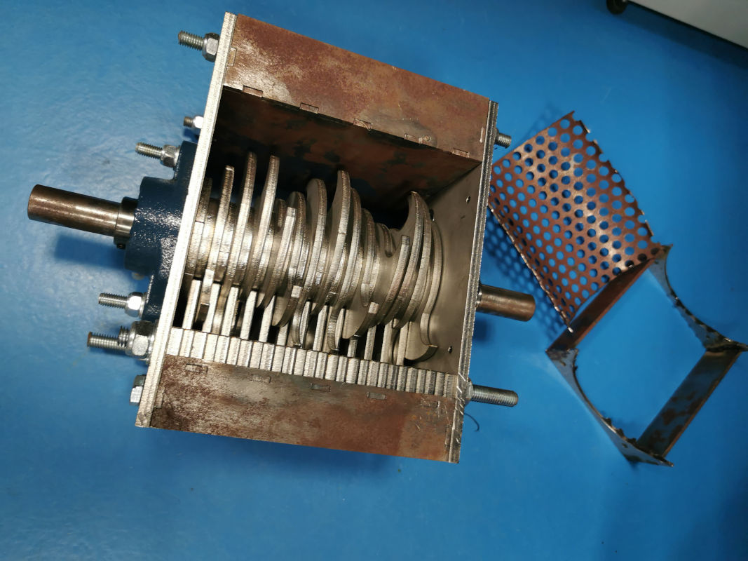
With an extruder and that crushed plastic we get our own filament.
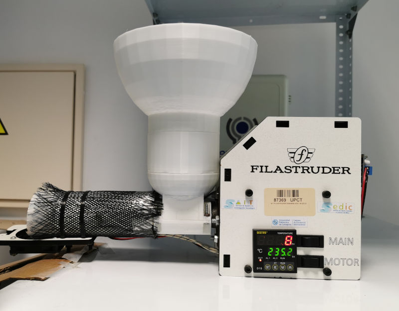
We have also made a winding for the filament that comes out of the extruder.
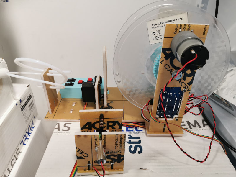
We use this recycled plastic filament in printers such as Prusa or Ender … and we get new models.
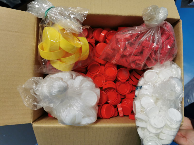
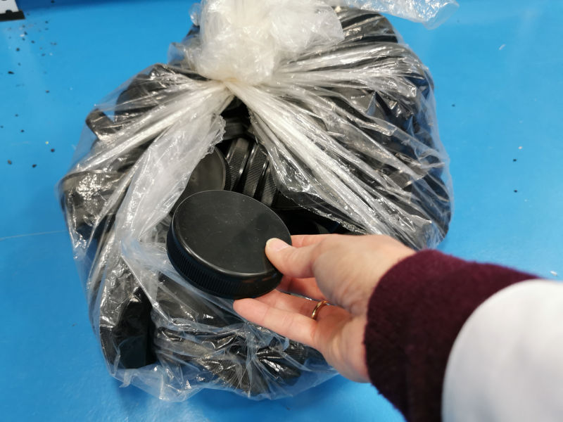
In addition to using these bases, we now recycle many types of plastic. In our laboratories there are containers that instead of throwing, we take advantage. Especially caps and containers.
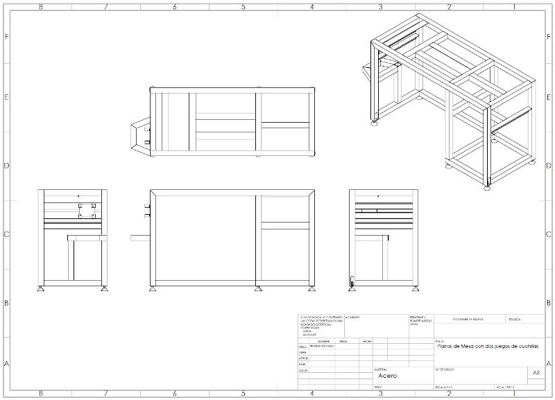
I am currently management a Final Degree Project to a student and we are creating a structure that integrates the entire recycling process, in which the plastic grinder mill takes the pellet to the extruder hopper and passes the filament to the extruder. overwhelming and we have our filament to place in the 3D printer. It will include safety measures so that the mill does not start up if it is not completely safe.
This is a diagram of the structure assembly that will integrate the plastic crushing mill, the extruder, the winding machine and all the accessories.
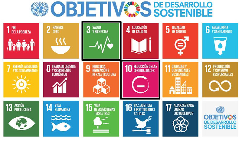
This Final Degree Project is framed within a Teaching Innovation Project, which aims to integrate the concept of the ODS objectives (Sustainable Development Goals) based on finding a sustainable way to manufacture prostheses, thus also doing social work.
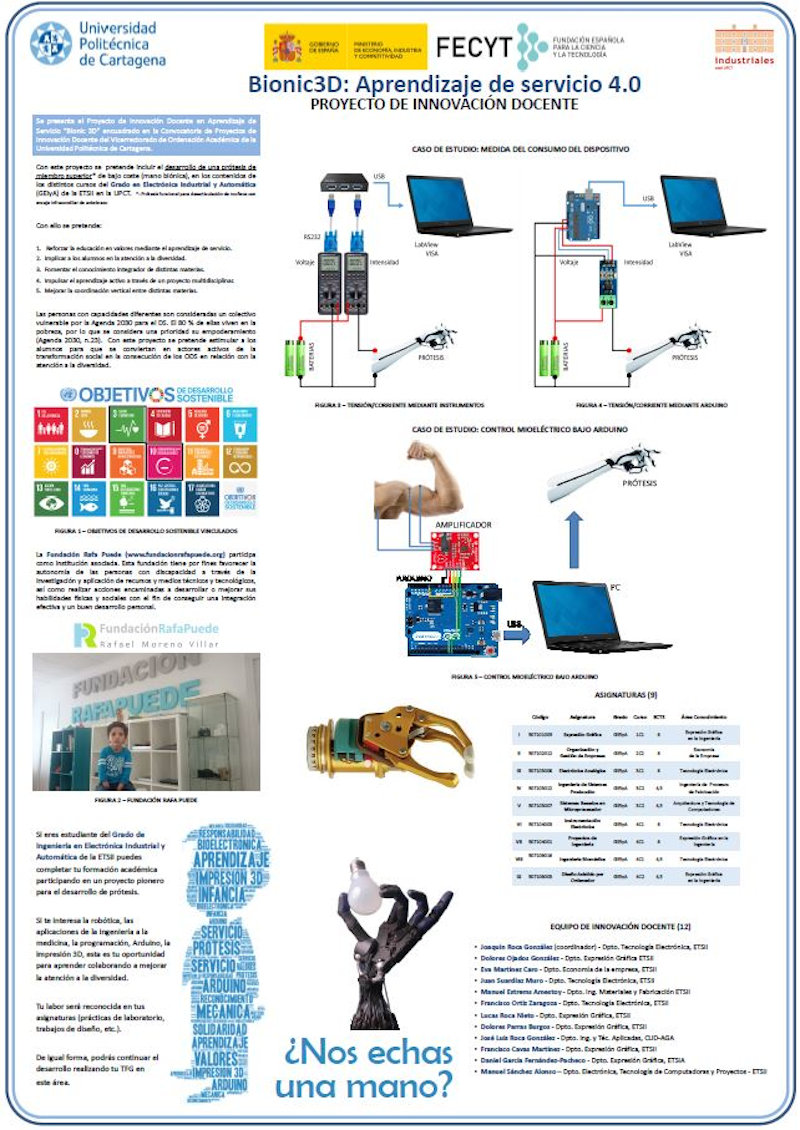
This is the part of the complete Teaching Innovation project that is being addressed in the Final Degree Project that I am currently leading.
On previous occasions other works have been to develop prostheses, especially for upper limbs, and mostly children.
These low-cost prostheses with recycled materials have allowed children to have a “hand” with which they were not afraid to play on the beach or do acrtivities that could damage the prosthesis. In most cases, they did not dare to carry out certain activities with their sophisticated prostheses of noble materials if they had one.
In this way, they have prostheses of their favorite superheroes that if broken can be fixed or reprinted.
6.C.2. Additive materials for 3D printing
In this field, we have carried out different studies to obtain our own additive material and to compare the results of these additives to the common 3D printing materials that are usually thermoplastic.
About five or six years ago I began to carry out research work to verify that this recycled plastic (ABS at first) and the models created with this material are of quality.
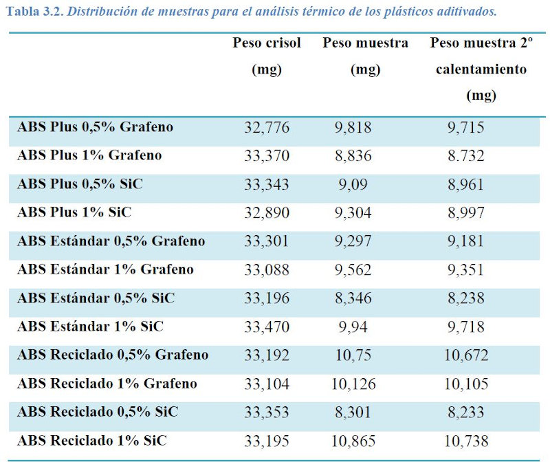
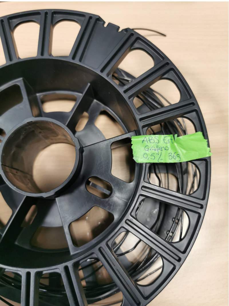
This results in another Final Degree Project directed by me in 2017 that studies the characteristics of this recycled plastic and additive with nanomaterials such as Graphene or Silicon Carbide.
STUDY OF THE IMPROVEMENT OF ABS PROPERTIES THROUGH THE ADDITION OF DIFFERENT NANOMATERIALS. RECYCLING AND REVALUATION
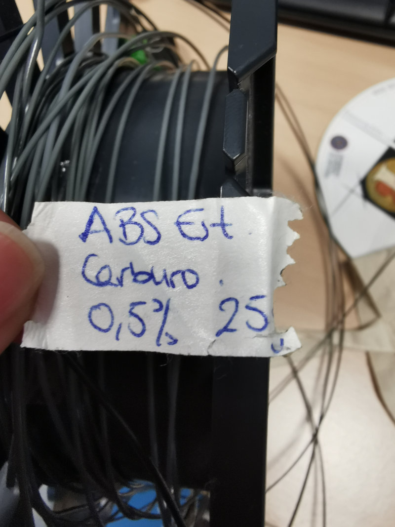
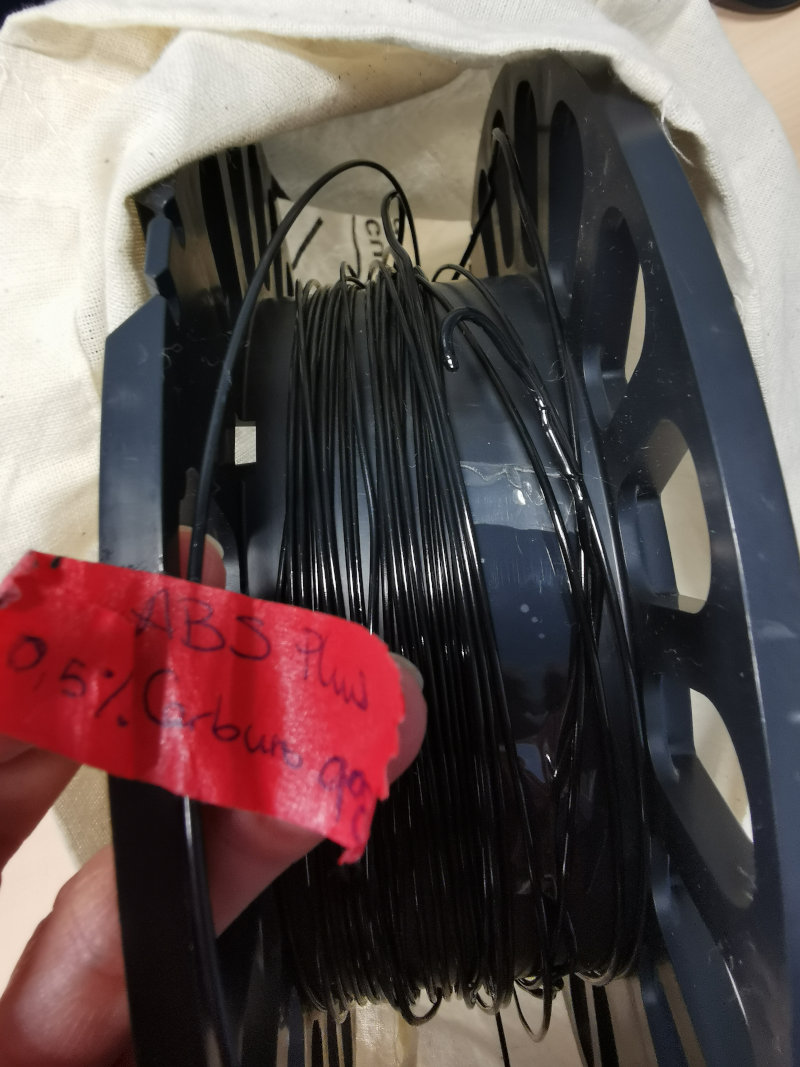
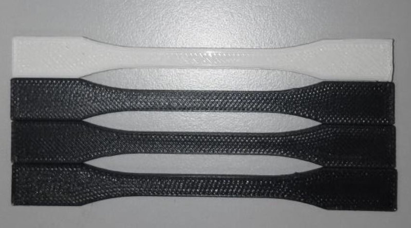
The trials of this study were performed on these patterns:
These are examples of the filaments obtained used to print 3D specimens subjected to tensile / traction, impact and hardness tests.
Some of the mechanical traction specimens tested::
These are the results and conclusions of this work:
Results:
The results obtained determine that the ABS can be recycled and reused, since very similar values have been obtained in the mechanical tests between commercial plastics (ABS Plus and Standard ABS) and the recycled ABS.
In addition, these values indicate that the recycling method used is appropriate, since what has been done has been to extrude the crushed plastic and reuse it, which does not affect the properties of the plastic and allows a new use to be established for material that has already fulfilled the function for which it had been designed.
This result can be very positive, as it helps not to pollute the environment, which is a great sustainability objective.
Conclusions:
It has been shown that an engineering plastic such as ABS, which has great properties on its own, can be even better with the addition of small amounts of nanomaterial, in this case, graphene or silicon carbide, which can place it as one of the best engineering plastics that currently exist, being able to meet the needs of very specific applications.
It has been concluded that the use of high-tech mechanisms is necessary to achieve good results in this area.
A new use for ABS has been determined, being able to be recycled and reused for other possible applications while maintaining their properties and even improving them, with the addition of nanomaterials.
Taking into account the amount of plastic that is produced daily on the planet, and the large amount that is disposed of polluting the environment, finding ways to recycle plastics to give them a new use is always a great find.
Future Research Lines:
This work may be the beginning of great discoveries, as there are possible future lines of research, such as:
-
Determine how much nanomaterial must be added to a plastic so that it starts to be a conductor of electricity.
-
Analyze at a chemical level the link that occurs between the polymer chains and the nanomaterial.
-
Optimize extrusion and printing techniques.
-
Carry out these tests with other materials such as PLA.
-
Deepen the study of 3D printing methods and geometries and positions of the models to be printed.
The drama was, that in less than a year after finishing the TFG this student died of sudden death, very young and everyone who worked with her was shocked.
It was terrible.
We continue to recycle plastic materials and perform tests, but we have not raised a study like this. Very recently, the mother of this girl called us to ask us to disclose and continue her work and now we have resumed it.
Other works related to 3D printing developed in the SEDIC and directed by me, have to do with the use of geometries obtained by 3D printing used as noise level reducers. As an example I refer to these two works that may be of interest:
NOISE ATTENTION USING 3D PRINTING METHODOLOGIES Link to document
ADDITIVE MANUFACTURING AND NOISE ATTENUATION IN OFFICE WORK Link to document
6.C.3. Surface finish of 3D printed parts
In this section I want to show some of the surface finishes that we apply to 3D printed parts and objects.
Sometimes we use products that reduce the stratification of material deposition layers.
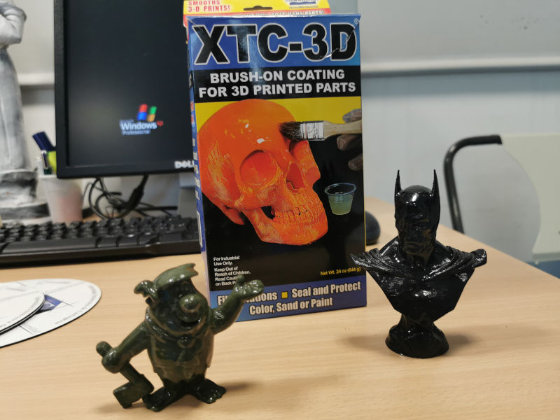
Other times we apply products and paints that simulate the material that the object originally had when it came from 3D scanning.
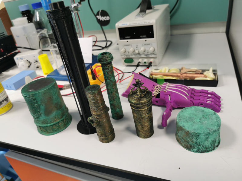
As is the case with these canyons rescued from the sea. From a sunken frigate called “Our Lady of the Mercedes” that carried within it a real treasure that Spain had to litigate with the treasure hunter company “Odisey” and won.
This treasure of gold and silver coins and valuable objects is now in the national museum of underwater archeology that is in our city, Cartagena.
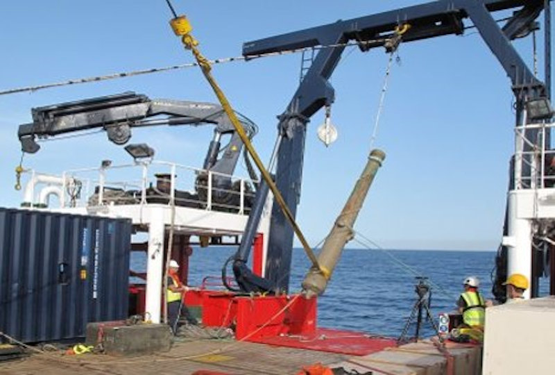
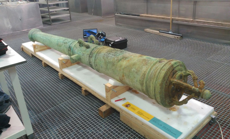
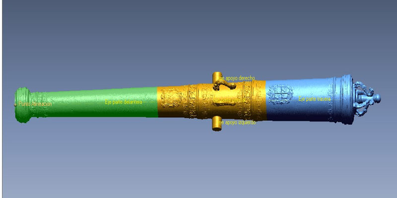
These are the two guns exposed in the museum at 1/2 size (approximately 2.5m in length)

This is one of the canyons scaled to 50cm in length.
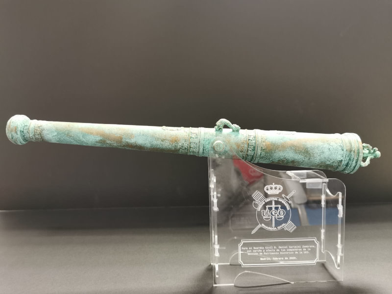
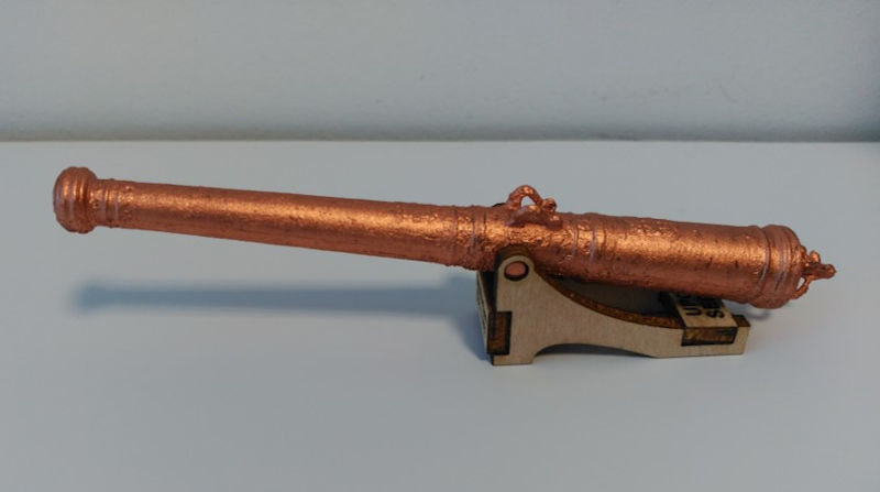
And this is a small replica of about 15cm in length and with another finish.
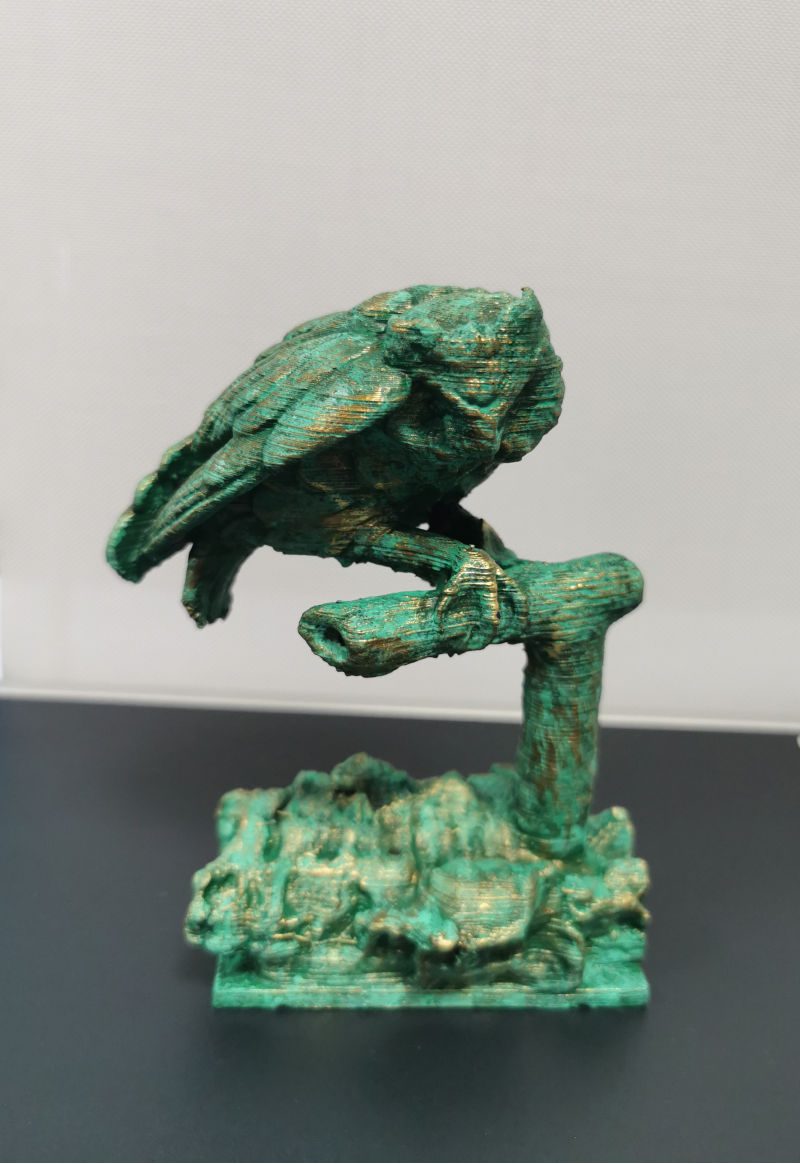
This other figure comes from a sculpture and its replicas were the trophies for the winners of a painting contest. We had to change the angle of position of the trunk to change the center of gravity of the set and that the bird did not fall forward due to its own weight.
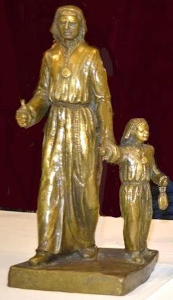
This other image is from a sculpture of Holy Week in our city.
It’s about casting imagination and looking for options so that the objects are as we have imagined or as they really are. We are always doing tests …
Sometimes we like the result and other times, not so much …