12. Molding and casting | Hook
- Review the safety data sheets for each of your molding and casting materials. Make and compare test casts with each of them:
Group assignment page: here.
My individual part:
I have reviewed the safety datasheets for each material in the Materials section.
I have compared and described them in the Casting the Mold and Casting the Model sections. We have skipped the test pieces due to restricted access to the FabLab and it’s also a process that takes a long time 😅
- Design a 3D mould around the stock and tooling that you’ll be using, mill it (rough cut + (at least) three-axis finish cut), and use it to cast parts:
Even when most of the experienced people in FabLabs seems not to be particularly interested on this kind of things, this resulted on one of the most interesting and funny assignments for me, cause it’s a very complete process where you are controlling every minimum aspect of it, involving from 3D modeling to fabricating the real physical object (like in 3D printing, but more complex and intended for mass production).
This is how we make Molding and casting:
- Molding: this stage is divided into two sub-stages:
- Pre-mold: or Mold preparation, consists of milling a material (which is wax in this case) to create a “negative mold”:
- 3D model and CNC program generation.
- Milling.
- Mold creation: consists of casting the pre-mold.
- Pre-mold: or Mold preparation, consists of milling a material (which is wax in this case) to create a “negative mold”:
- Casting: as the name suggests, it consists of casting the model using the Mold. 🤷♂️
Taking the description from above as foundation, my documentation is separated as:
- Mold preparation, that describes the from the 3D model to the Milling.
- Casting, described for the mold and the model itself.
- For 3D modeling and NC program generation, I used Fusion 360.
- The milling machine I used was the Roland MonoFab SRM-20.
- The tool I used end mill I used was a 3.8mm flat.
Mold preparation
I used Fusion 360 on its Manufacture Workspace.
3D model
Since I didn’t really need to cast anything for my final project, I made just a didactic piece for learning the technique.
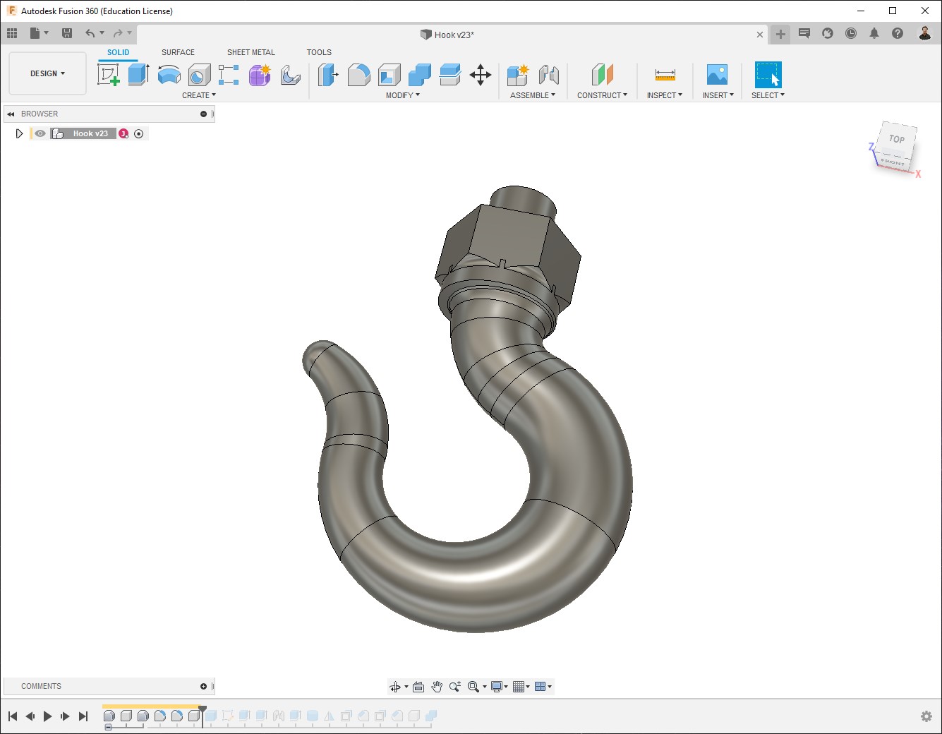
In this case, I used a hook that I modeled during the 2D and 3D Design week of the Fundamentals of Digital Fabrication course:
3D_Hook by Jeff Josue on Sketchfab
I used Fusion for this task, once there we work on the Design Workspace first…
-
I opened the model:
-
Since my design looks the same from the front and the back, I can just prepare one part and make mirror a the end, so in this case I drew a cube which size is half of the wax block I’ll use:
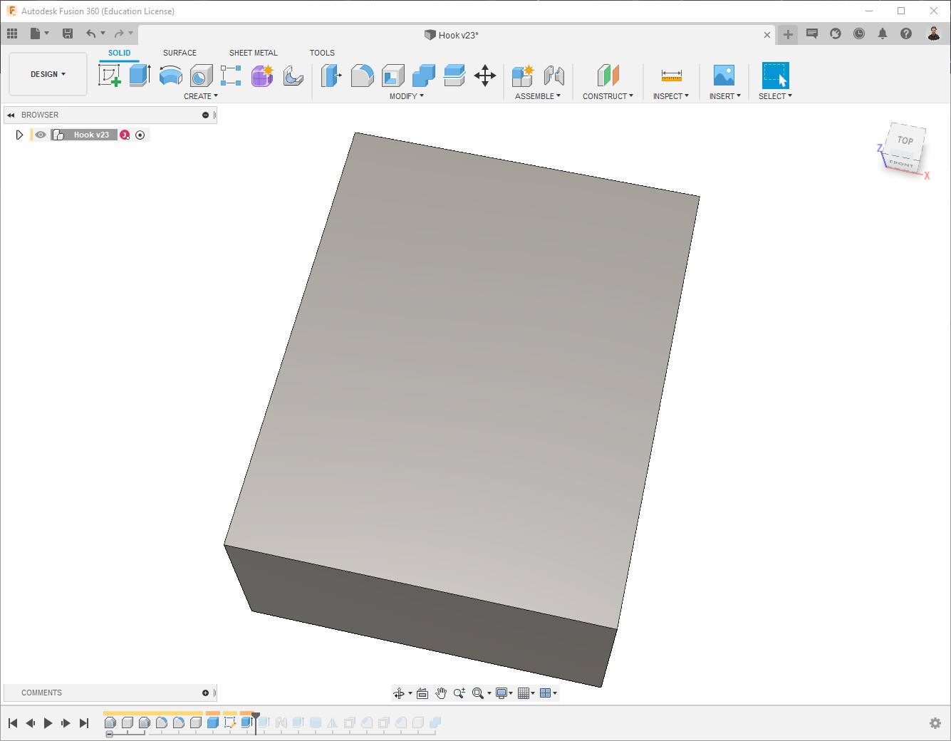
Block size: 141.5 x 91.5 x 37 mm; Then in the model it is 70.75 x91.5 x37 mm.
-
I re-sized the hook to make it fit into the block. (On real applications you would rather select the size of the block depending on the needs for your model, but in this case it’s just for learning).
-
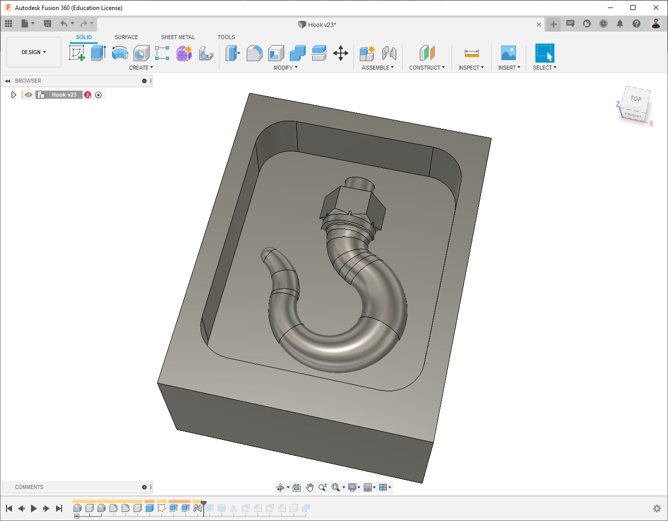
I made a pocket on the block and put the hook inside:
-
To make the mold match, it’s necessary to add guides; the guides can be either pins or a contour, I chose pins.
-
Also to pour the substance to make the mold, I added a cylinder on top:
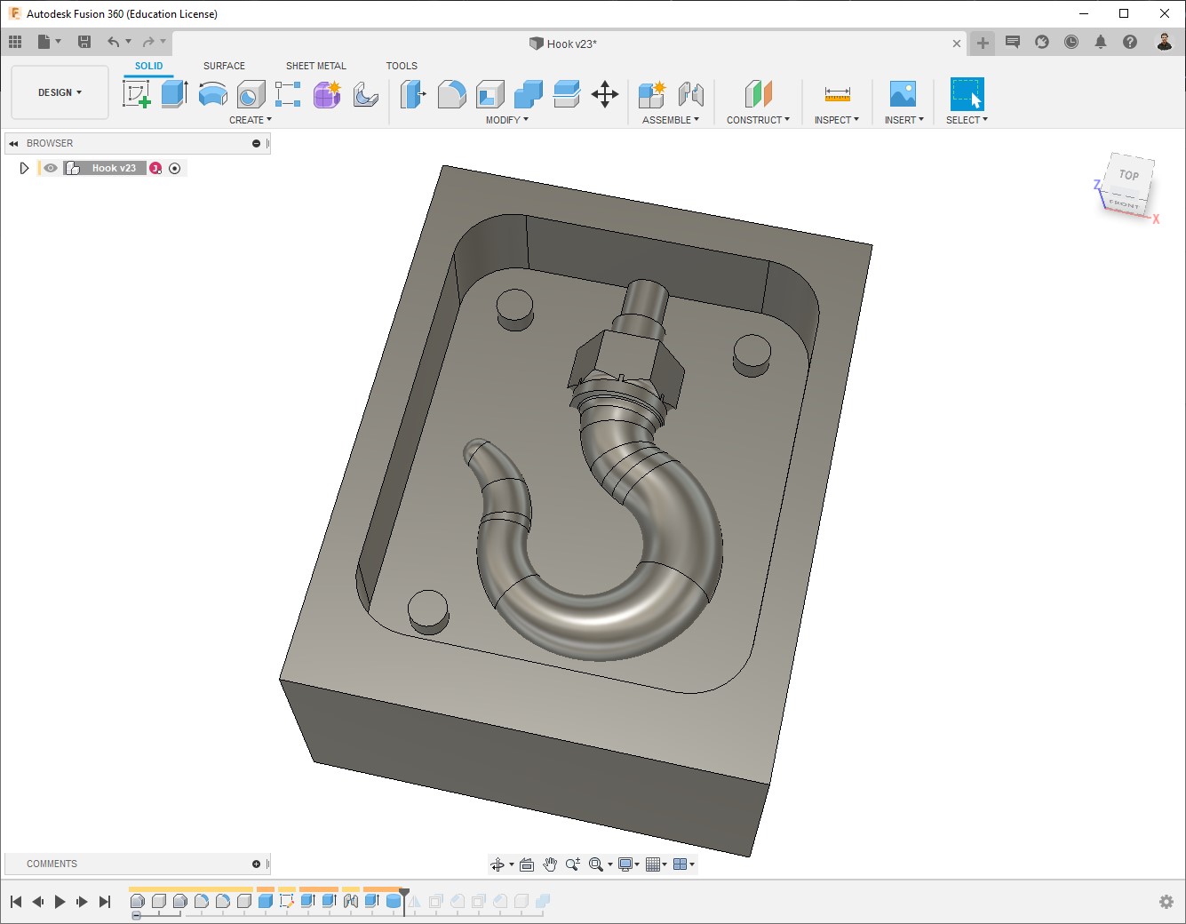
This hole can be made directly on the mold afterwards, don’t really need to be part of the model.
-
I made mirror and pushed the pins, then I have one part with male pins and the other part with female pins. If you rather using contour instead of pins, make sure you do the same. A good recommendation is not to make the guides completely straight, but with an angle so then fit a bit easier, also take in account some tolerance so the male guide is slightly smaller then the female one:
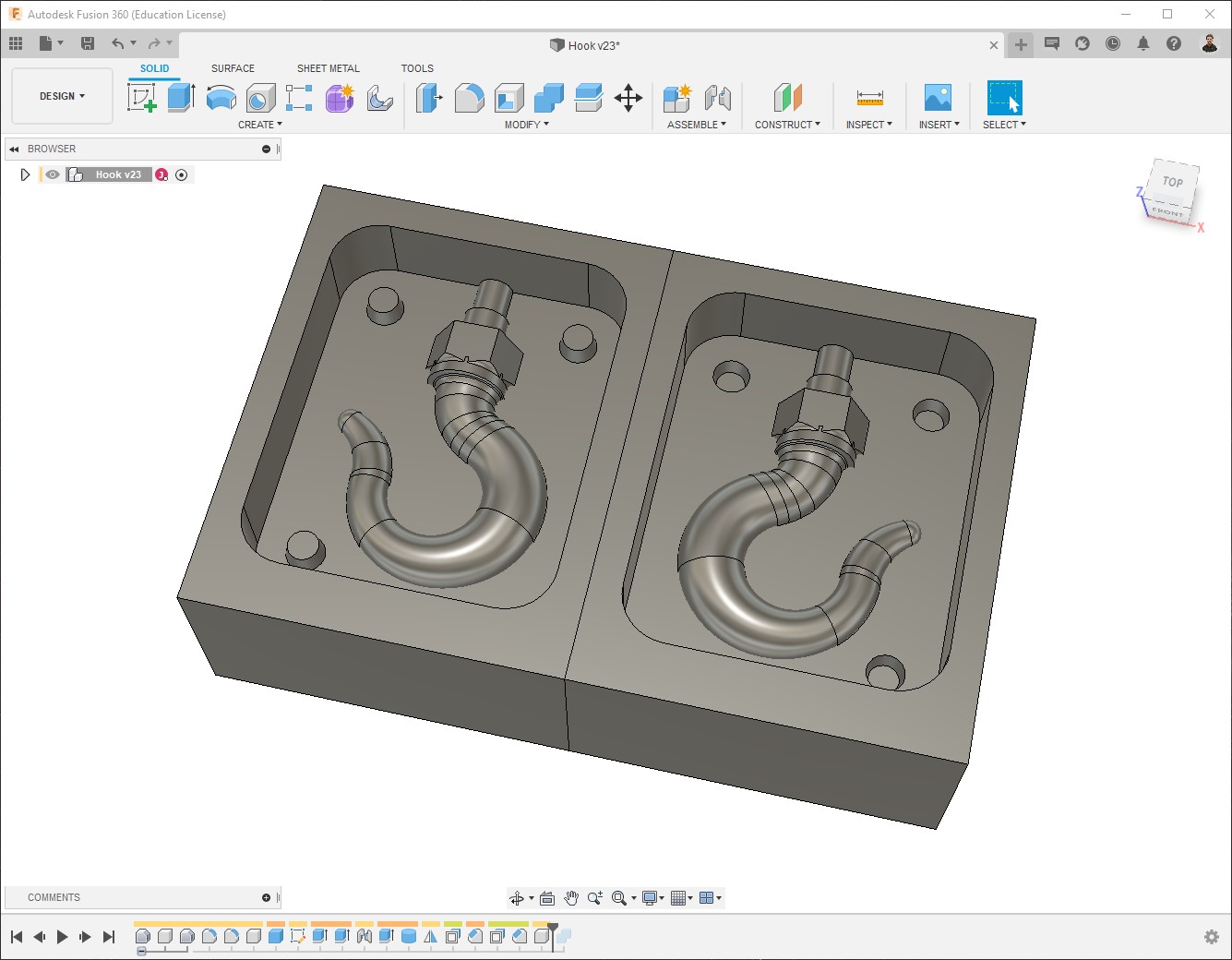
-
Eventually I merged them together, creating a new component so the Manufacture section is easier:
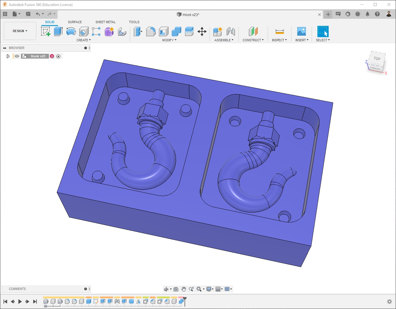
Also made it blue, just to match the color of the wax 😁.
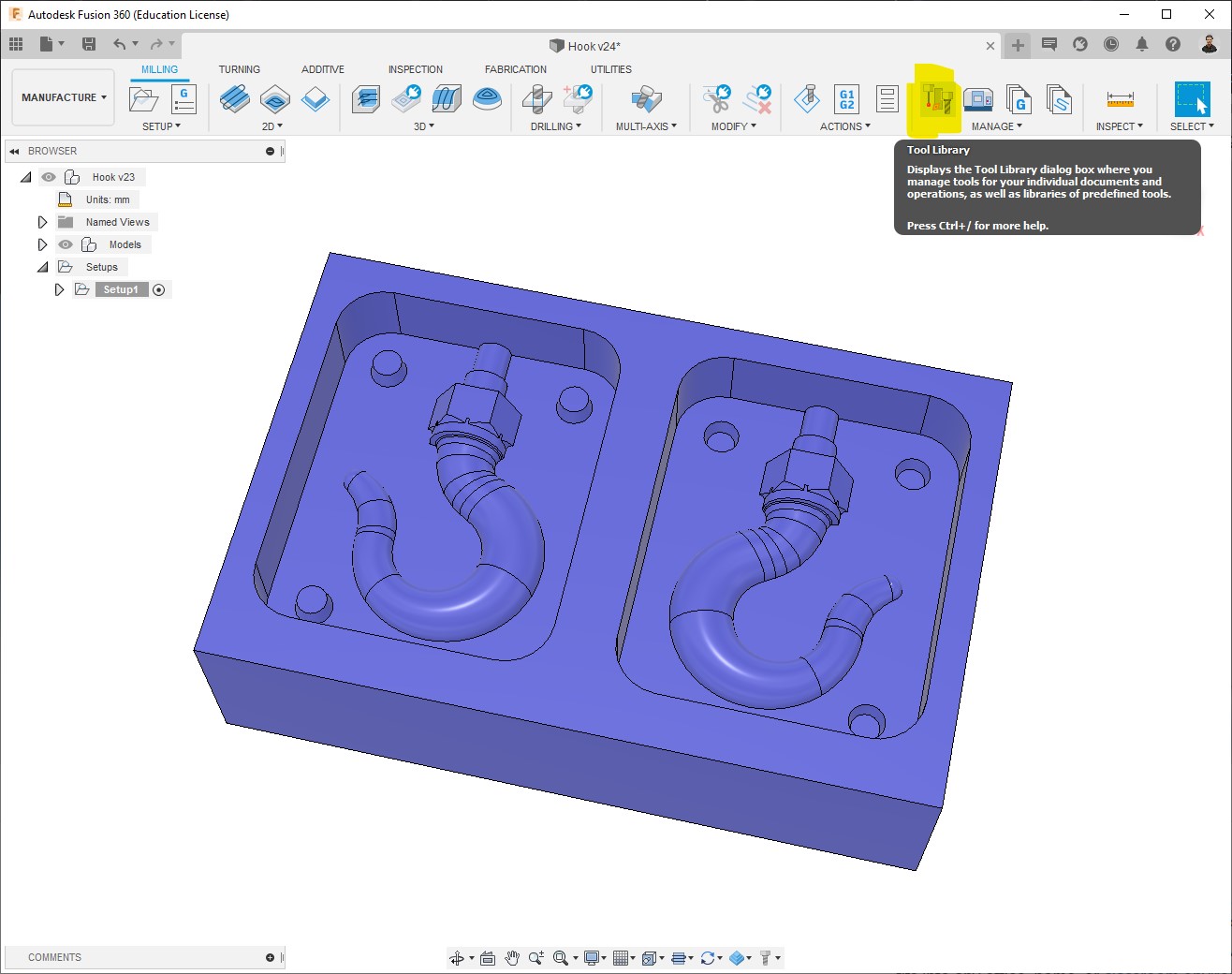
CNC program generation
Tool configuration
Fusion 360 already offers a library of tools for drilling, milling, and more; but to customize and make it fit with our reality, it’s good to configure by ourselves the tools that we are going to use.
In this case, due to different reasons (mainly Corona restrictions), it was possible for me to use only a 3.8mm flat end mill, so I’ll be using it for all of the process.
-
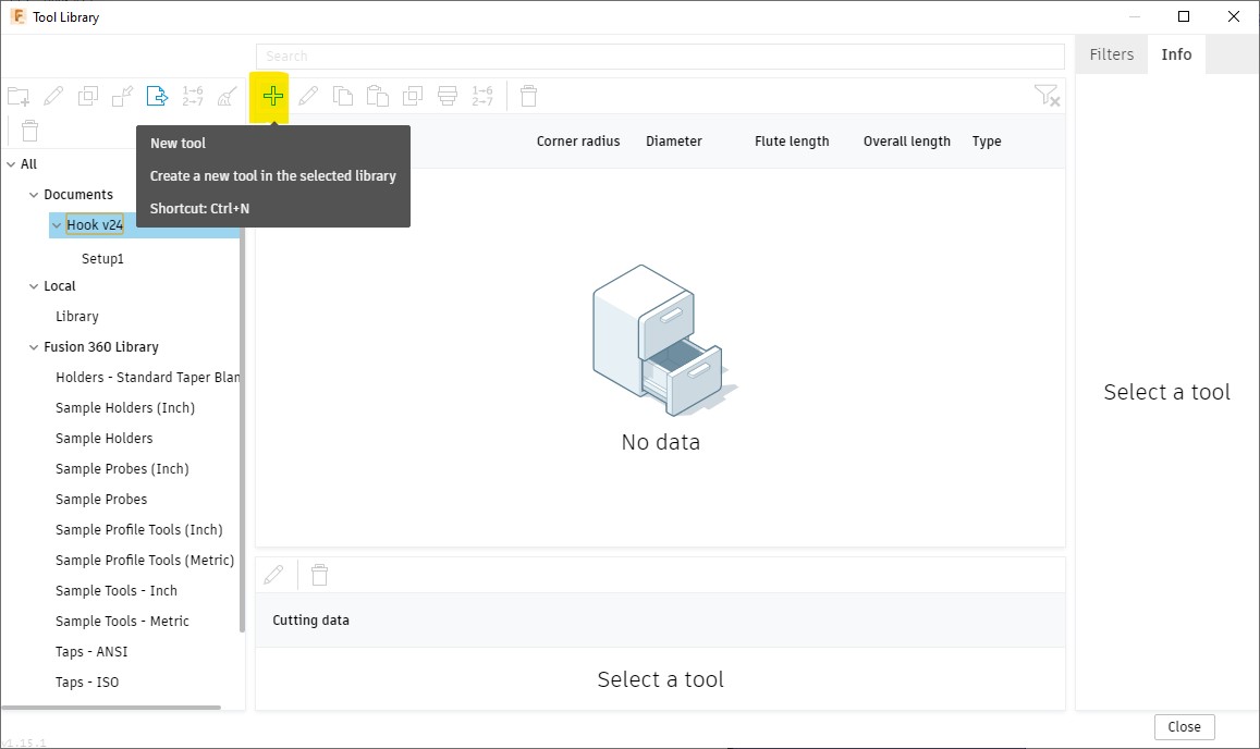
Open Milling > Manage > Tool library:
-
Create a New tool:
-
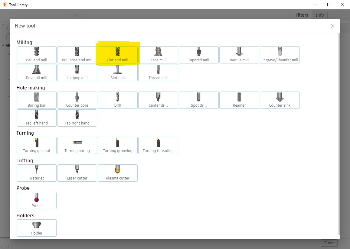
Select the type of tool, in my case it’s a Flat end mill:
-
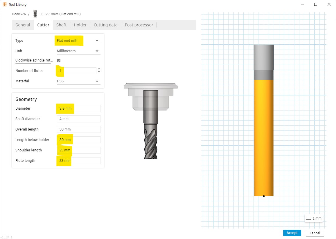
The Cutter tab is the most important to configure at this point, Cutting data can be configured independently for each process when using the same tool for more than one, also it can be easily changed during the machining. Diameter is used for creating the toolpath; and the highlighted lengths are essential afterwards, during simulation, to detect possible collisions:
-
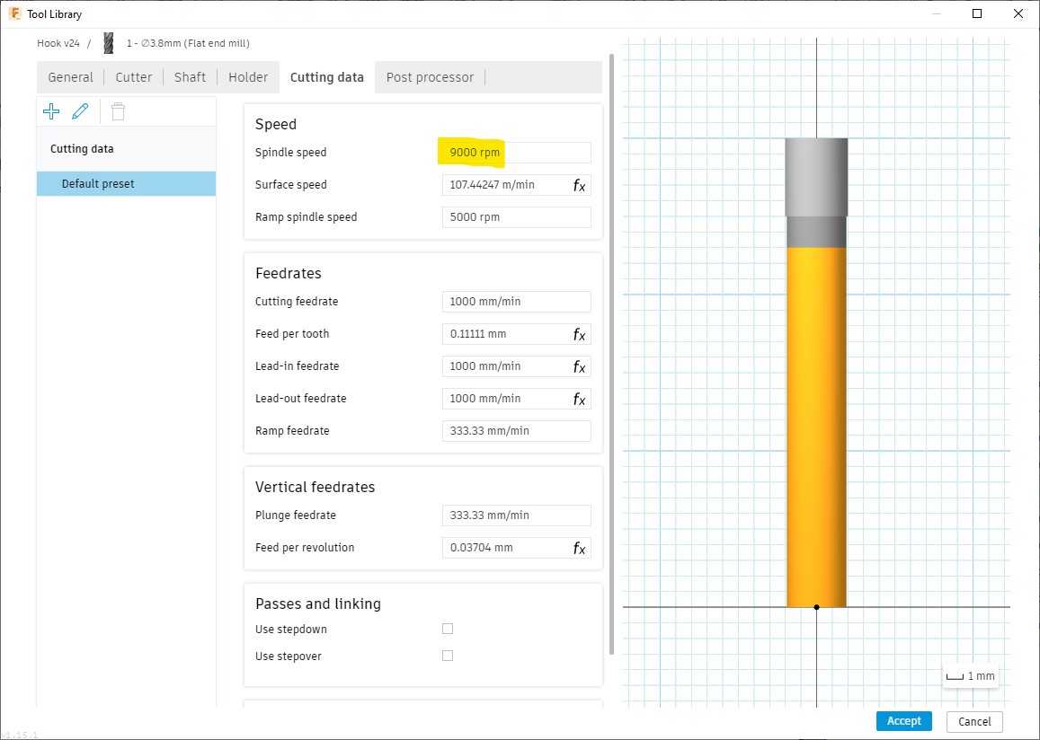
I also set the Cutting data already cause I didn’t change it in any process, just set the Spindle speed to 9,000RPM which is approximately the maximum speed I have seen on the V-Panel software for this machine, I left the rest of parameters by default, since the material to machine is wax, there is practically no danger of accidents:
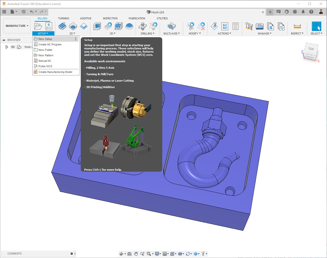
Setup preparation
This is the first step before configuring the processes.
-
Create a New setup:
-
Edit the Setup:
-
Select WCS (Work Coordinate System); it depends on the machine we are going to use, in this case is on the bottom-left corner:
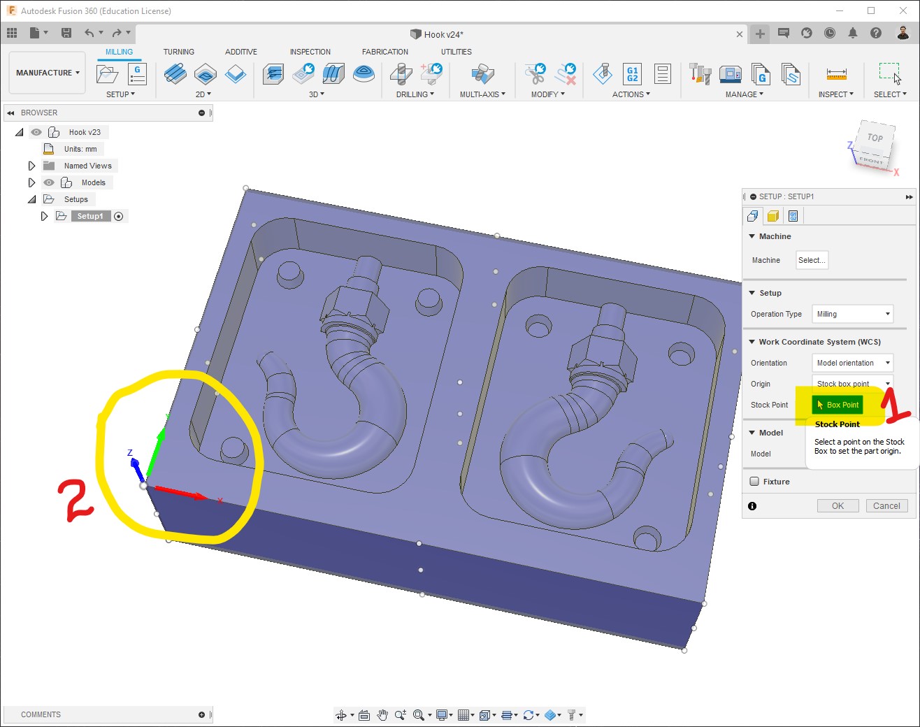
-
Select Model, clicking on it:
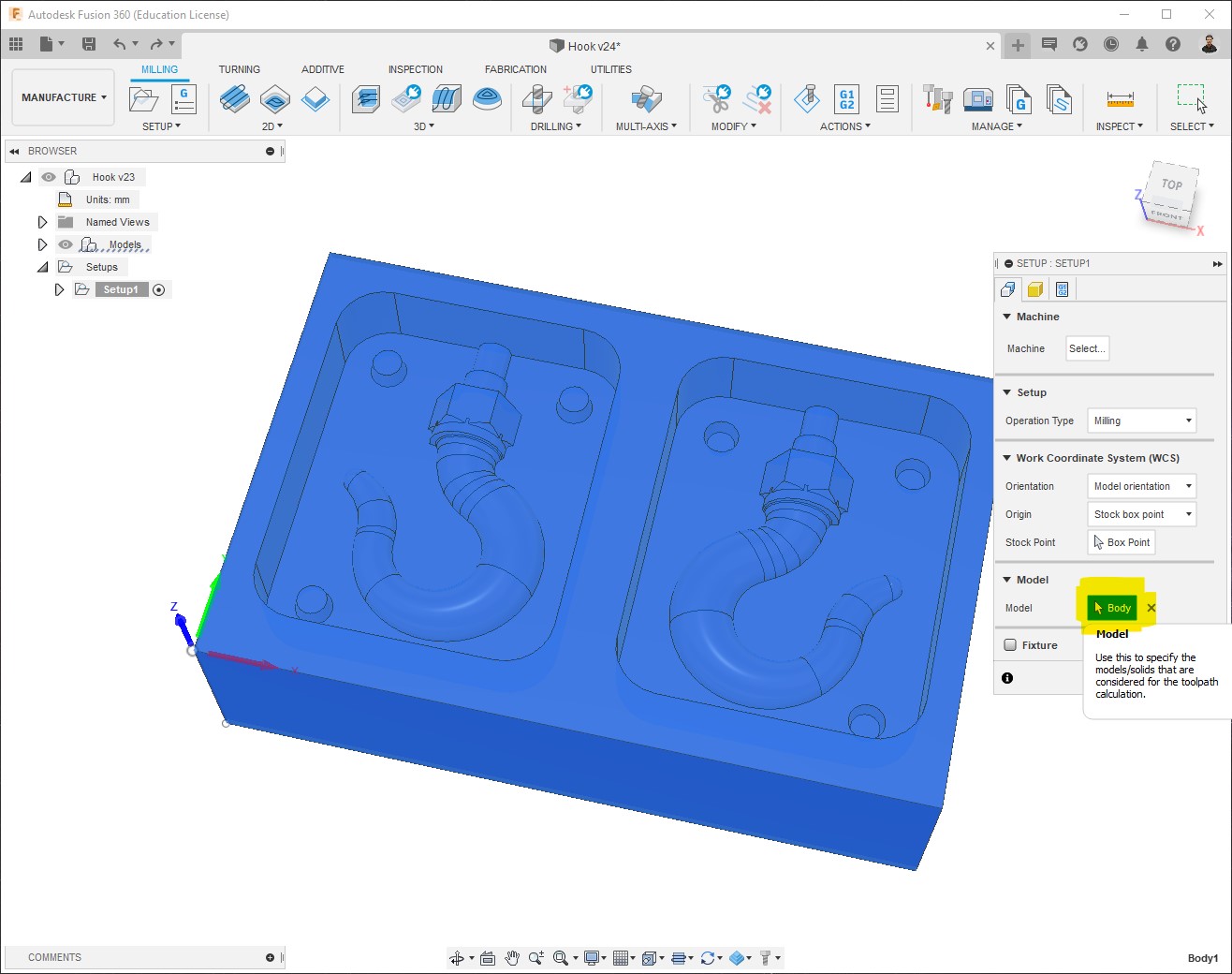
-
I select “No additional stock”, and make sure that the Stock dimensions are right, it is automatically set when we selected the WCS:
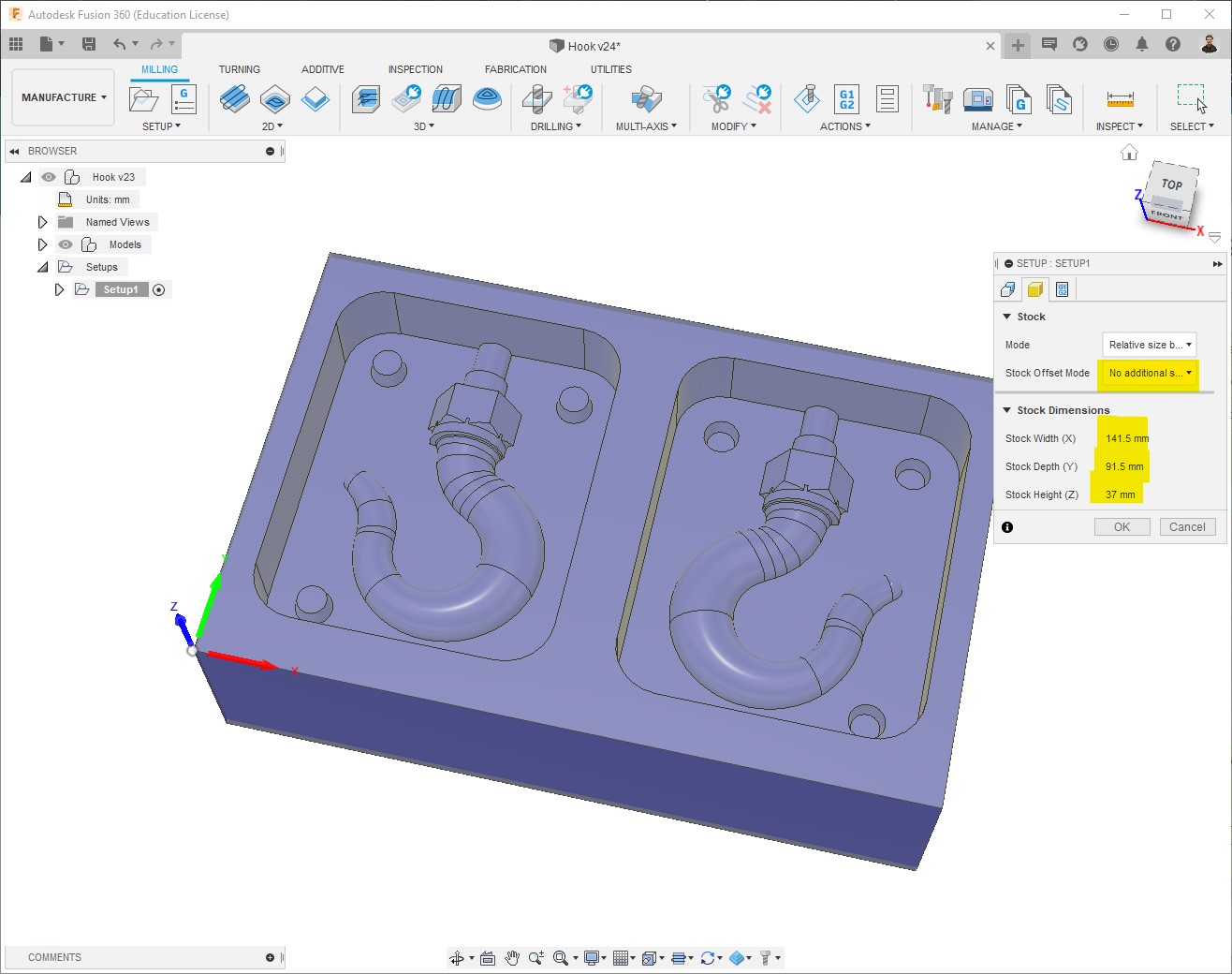
-
Toolpath configuration
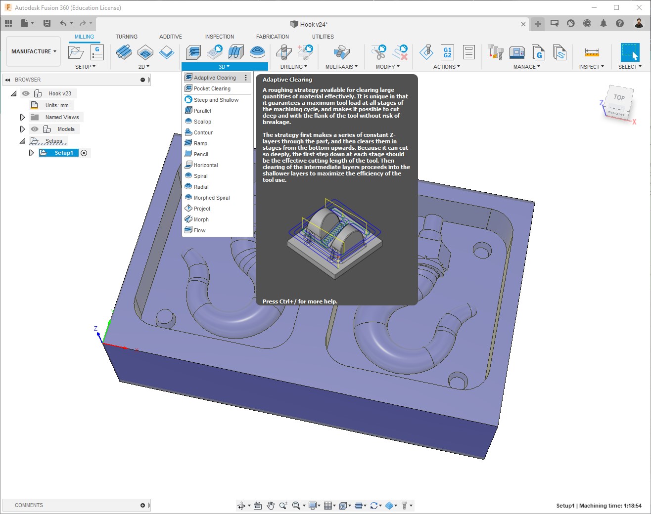
Rough Cut
The first process consists of removing the biggest amount of material, for that I used Adaptive clearing:
-
Select Tool:
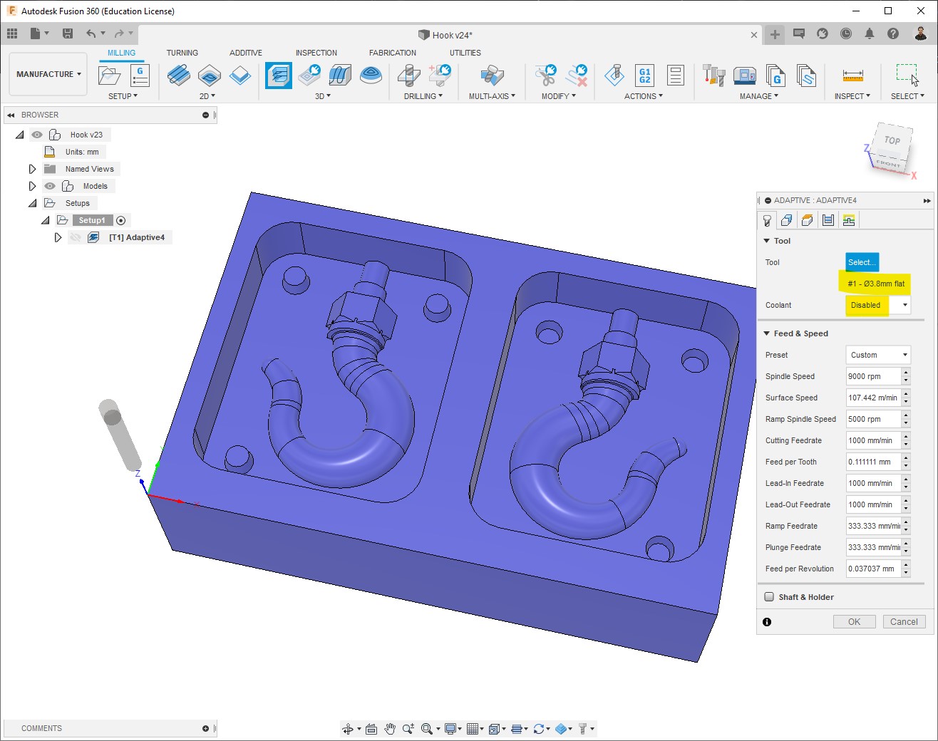
-
This is the Passes configuration that I used:
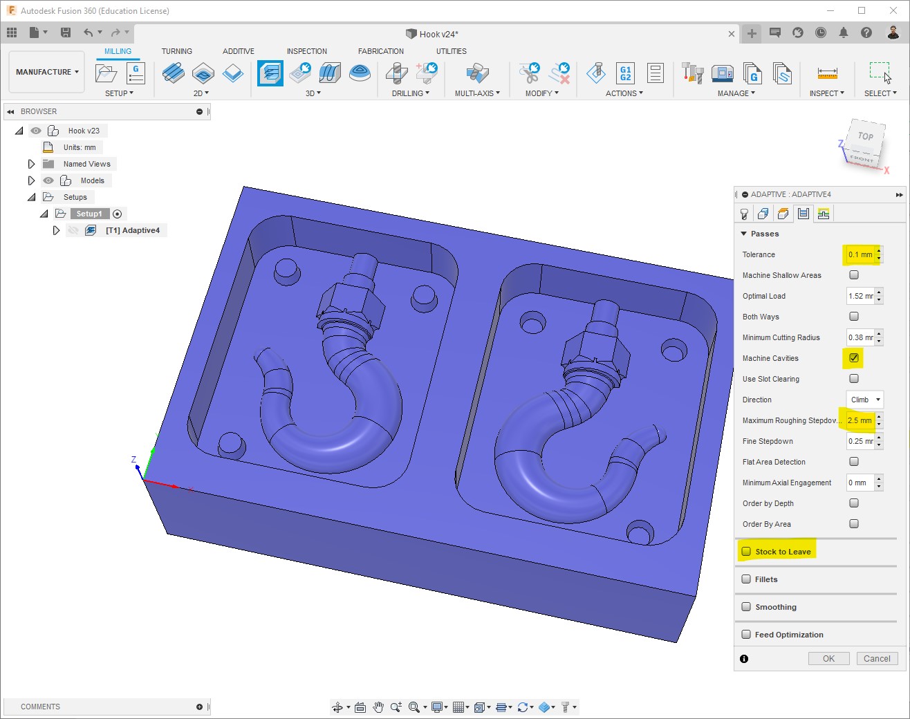
-
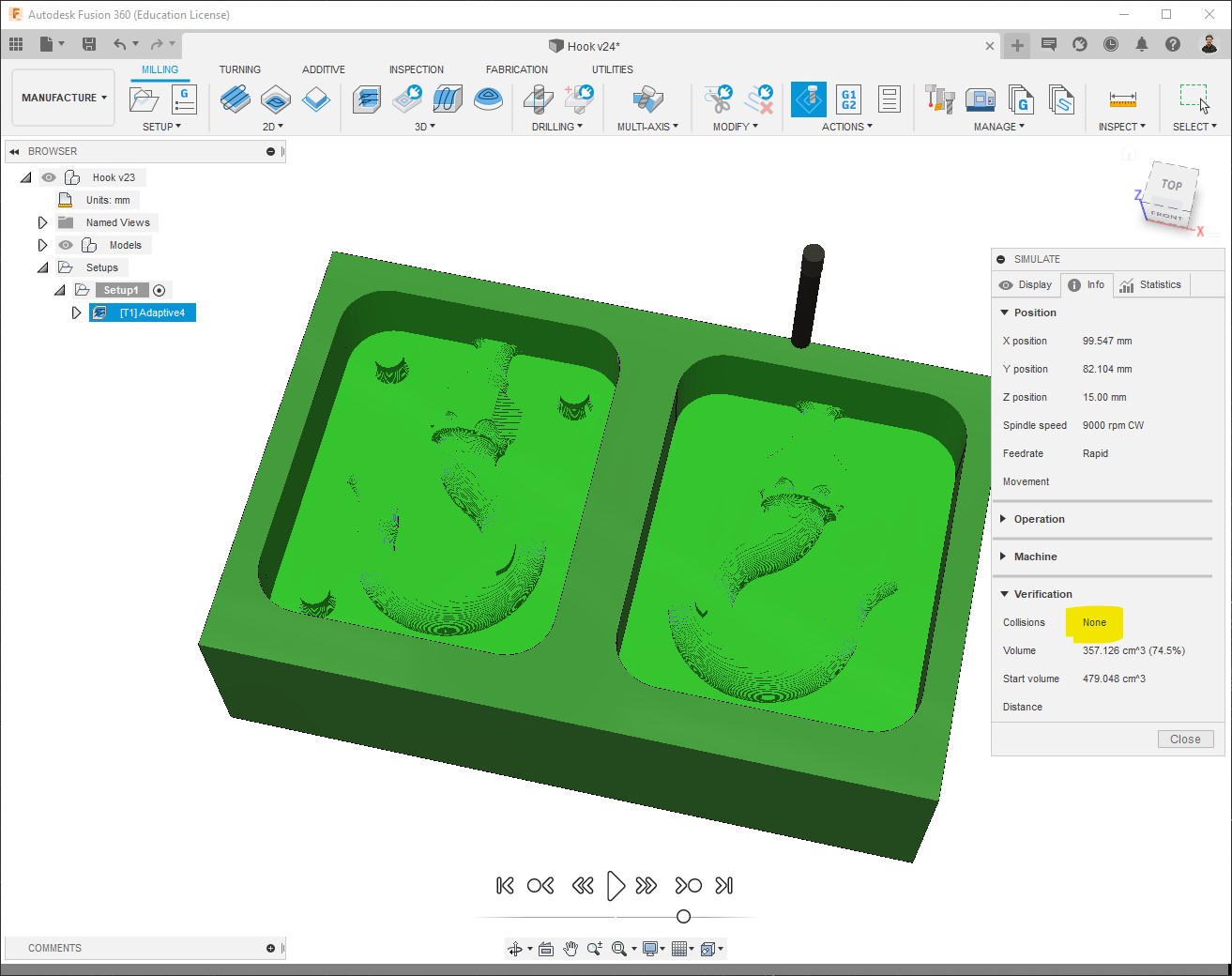
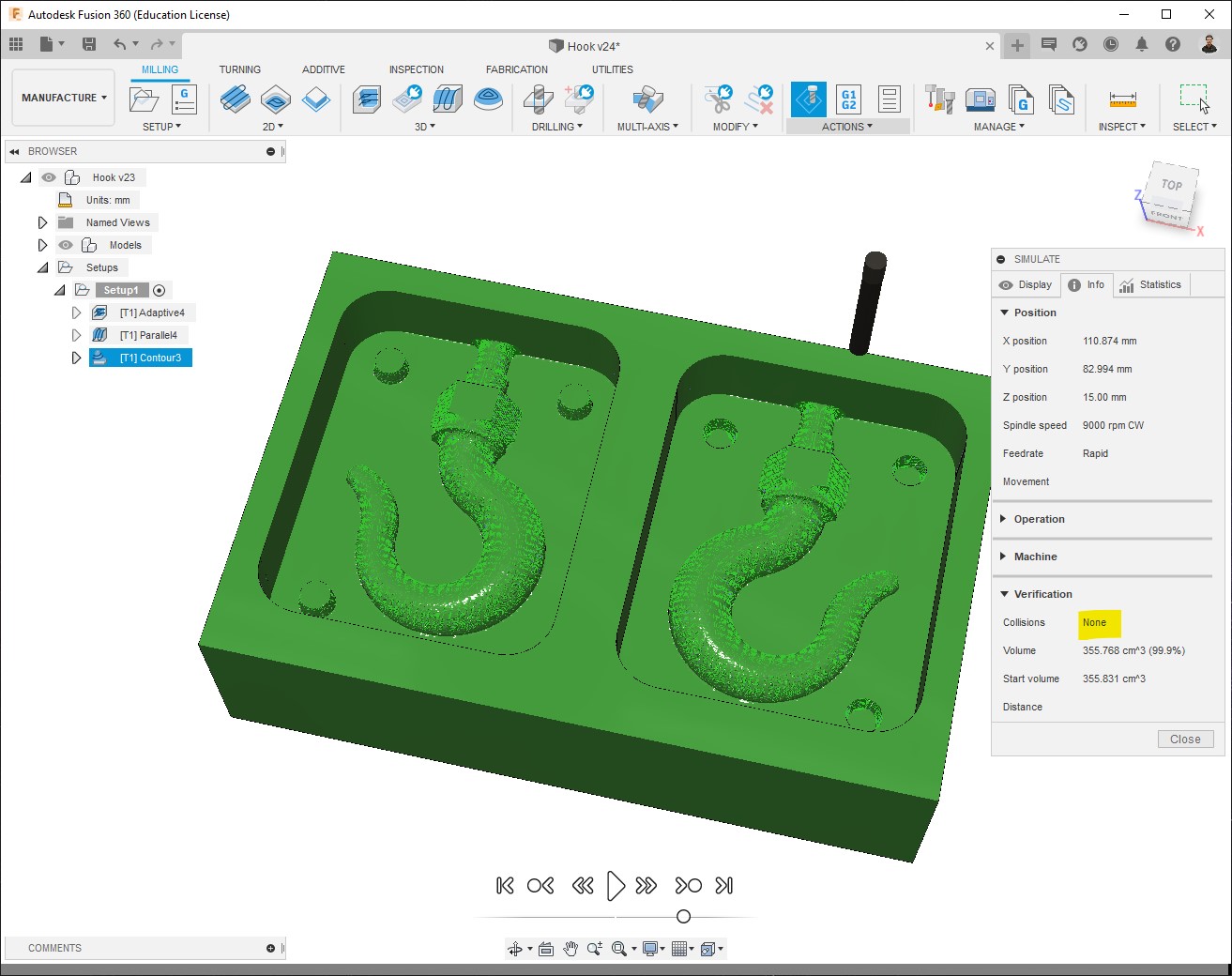
The toolpath will be generated, it could take a few seconds depending on the process, then you can see at the bottom right the machining time, which is 1h06mins for this first process, this time is in reality just an approximate value. Next step is to Simulate:
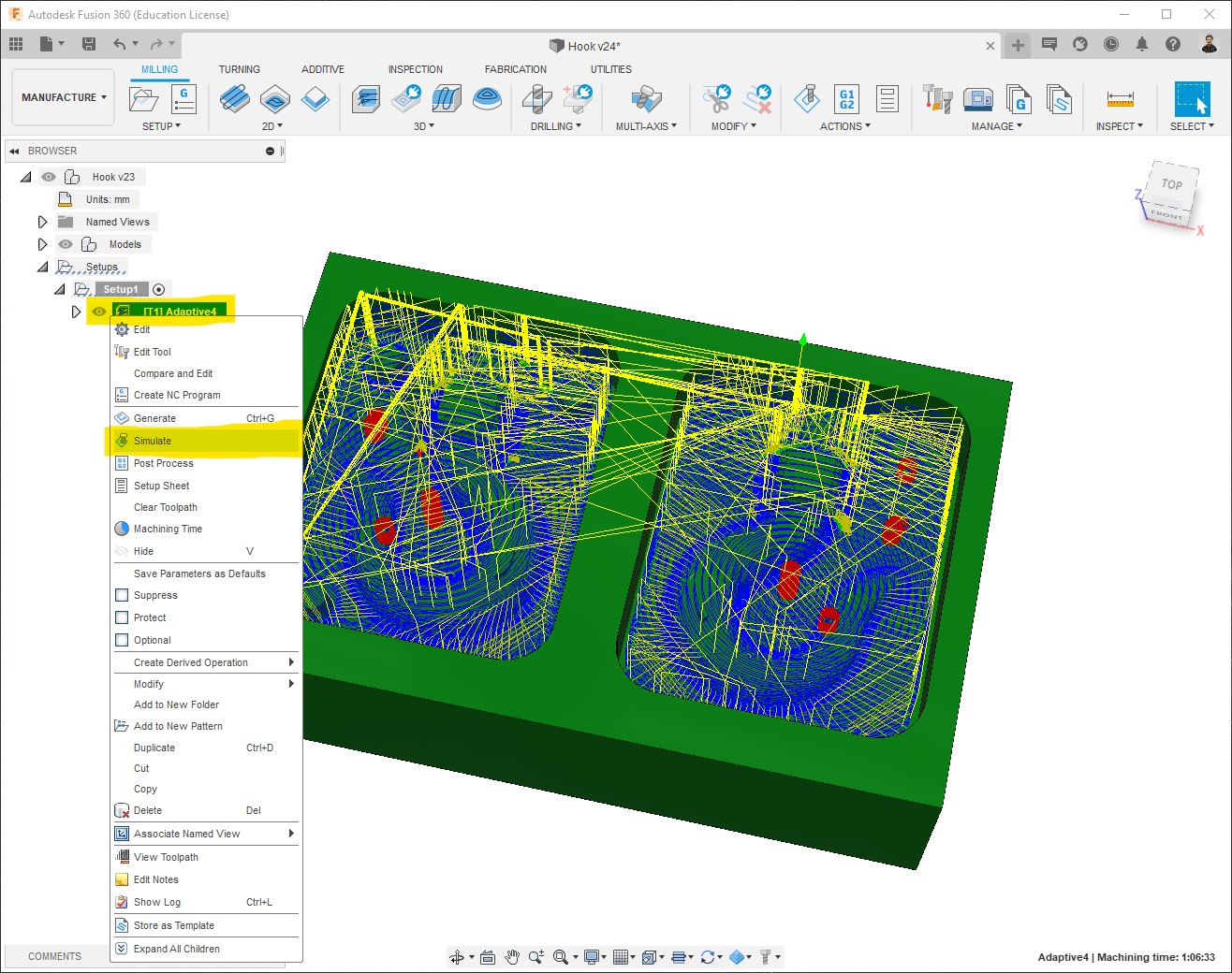
-
In addition to have a preview of the machining, what we need to check here is the info > Verification, to make sure that there are no Collisions:
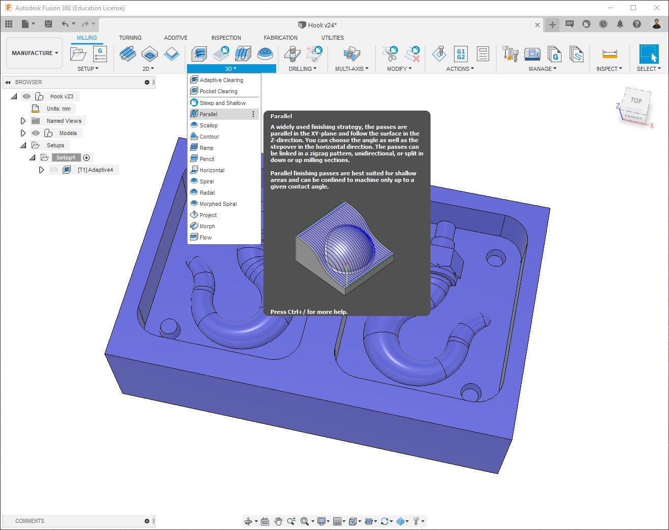
Pre-finish Cut
The second process consists of removing rather smaller amount of material to prepare the piece for the finest process, for that I used Parallel:
-
Using the same tool:

-
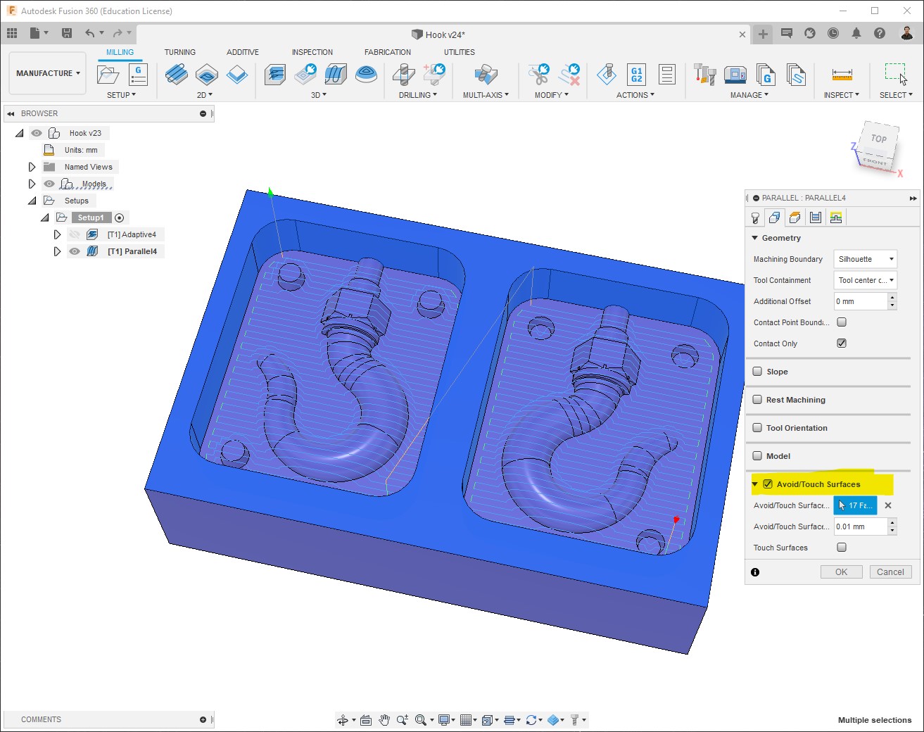
For this process, since it automatically passes over the whole model, we can use the Avoid surfaces option to ignore the top of the stock and its walls to save some time:
-
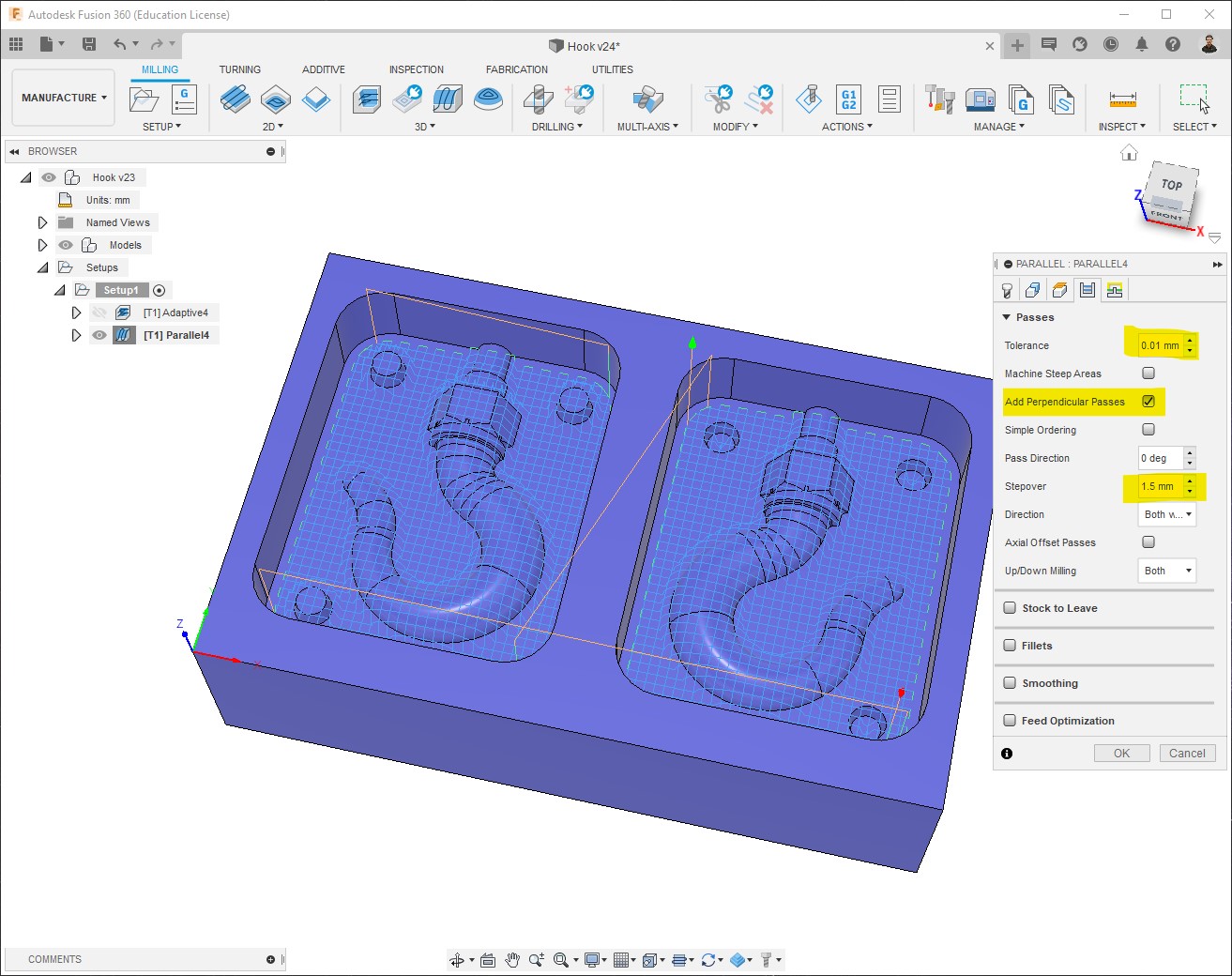
For the Passes, I set a stepover of approx. half the diameter of the end mill:
-
Machining time = ~0h12m. No collisions:

Finish Cut
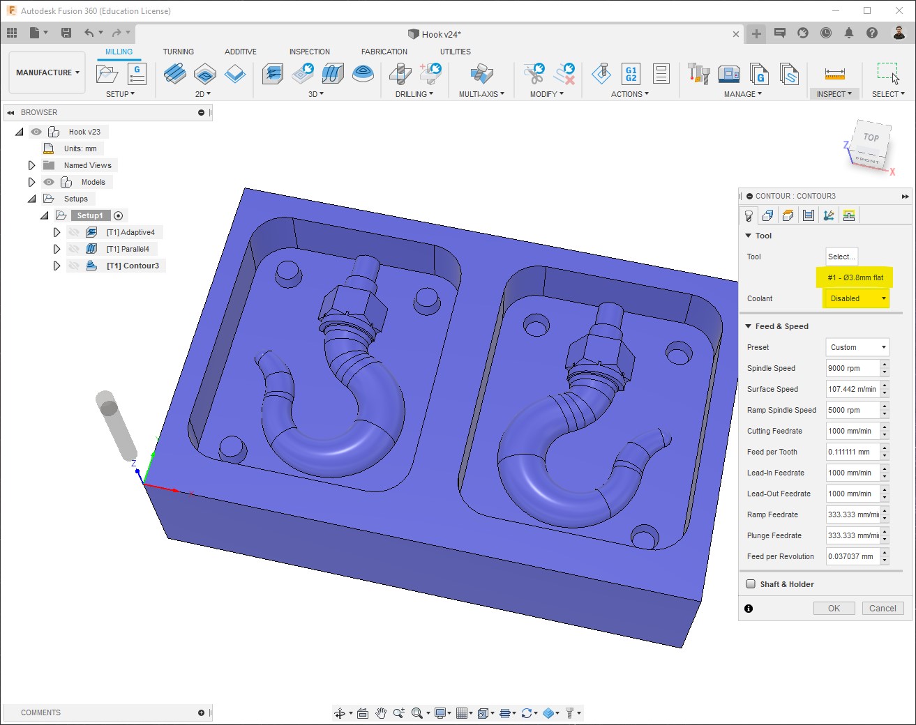
The third and las process consists of a finish cut, to minimize as more as possible any roughness, for that I used Contour. I chose it based on what I consider is the best for the shapes of my design, other models could require different process types for the finish:
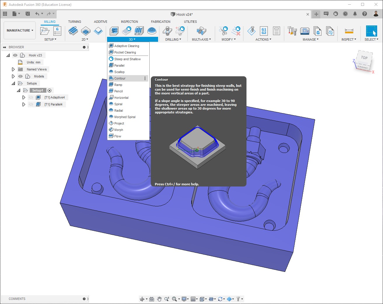
-
Using the same 3.8mm flat end mill:
Note: the best tool for a finish is a Ball and mill, which offers a smoother and nicer result, but as I mentioned before I used the same tool for the whole work.
-
For this process, since it automatically machines every vertical surface, we can use the Avoid surfaces option to ignore walls of the stock to save some time:
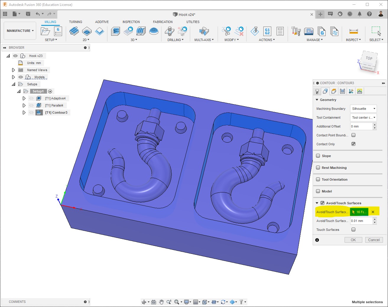
-
For the Passes, I set a stepdown 0.1mm which is the key parameter to achieve a better result on this process:
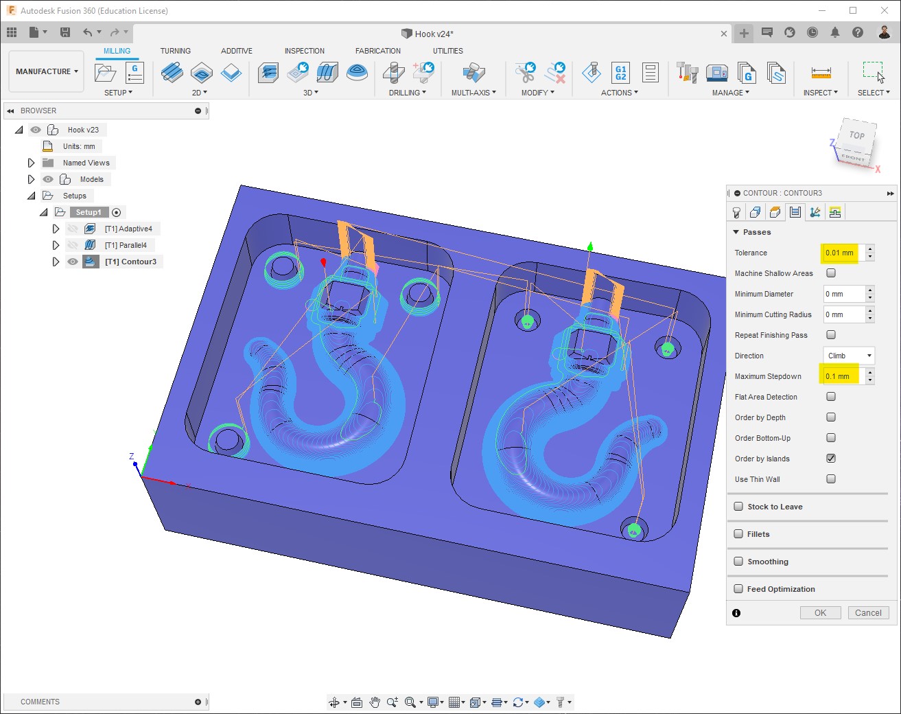
-
Machining time = ~0h34m. No collisions:
G-code generation
Once we have our toolpaths and we made sure there are no collisions, we can create the Numerical control (NC) program. It is also done on the Manufacture workspace.
-
Milling > Setup > Create NC program:
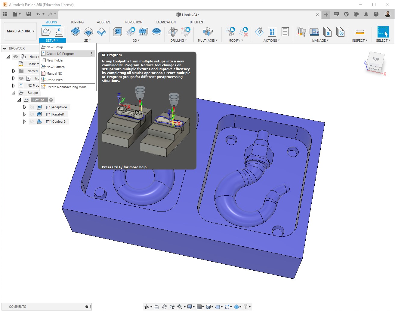
-
In Settings what we need is to configure the machine to use, since I used the Roland SRM-20, but Fusion doesn’t have that machine on list, I selected the Roland MDX-40 which works perfectly:
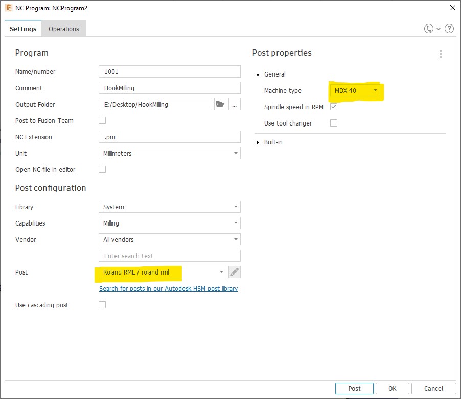
Note: If Roland MDX-20 was selected, the result would have been noticeably.
-
In Operations we just need to select the processes for which we want to create the program, then Post:
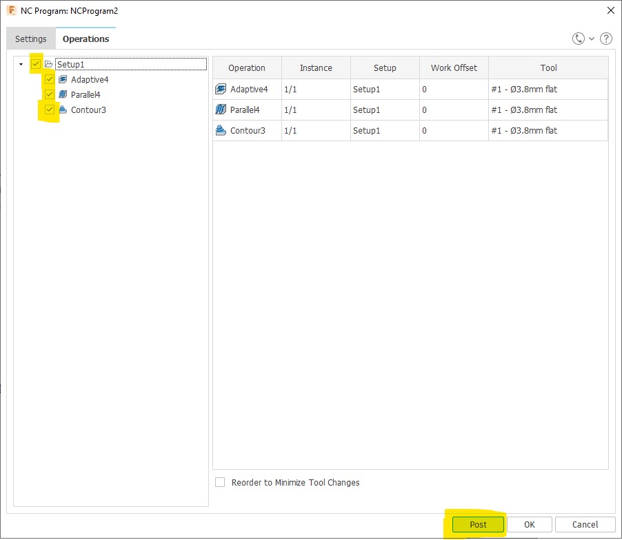
-
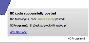
Done!
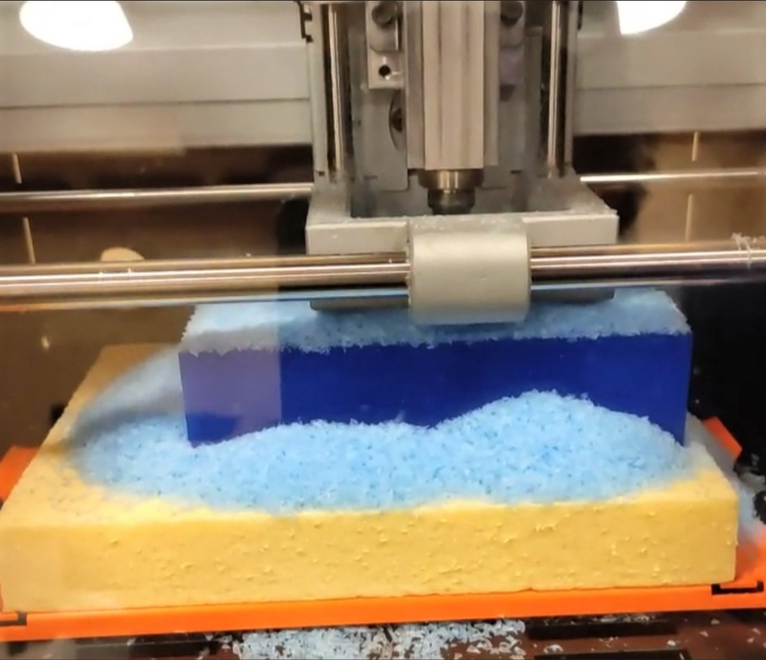
Milling
In this section I don’t describe the whole process, cause every machine has its own dimension, software, ways to set home, etc.; Then the my results from each process are:
Material milled: wax
Dimensions: 141.5 x 91.5 x 37 mm
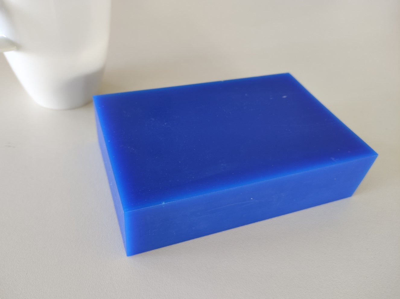
-
Rough Cut:
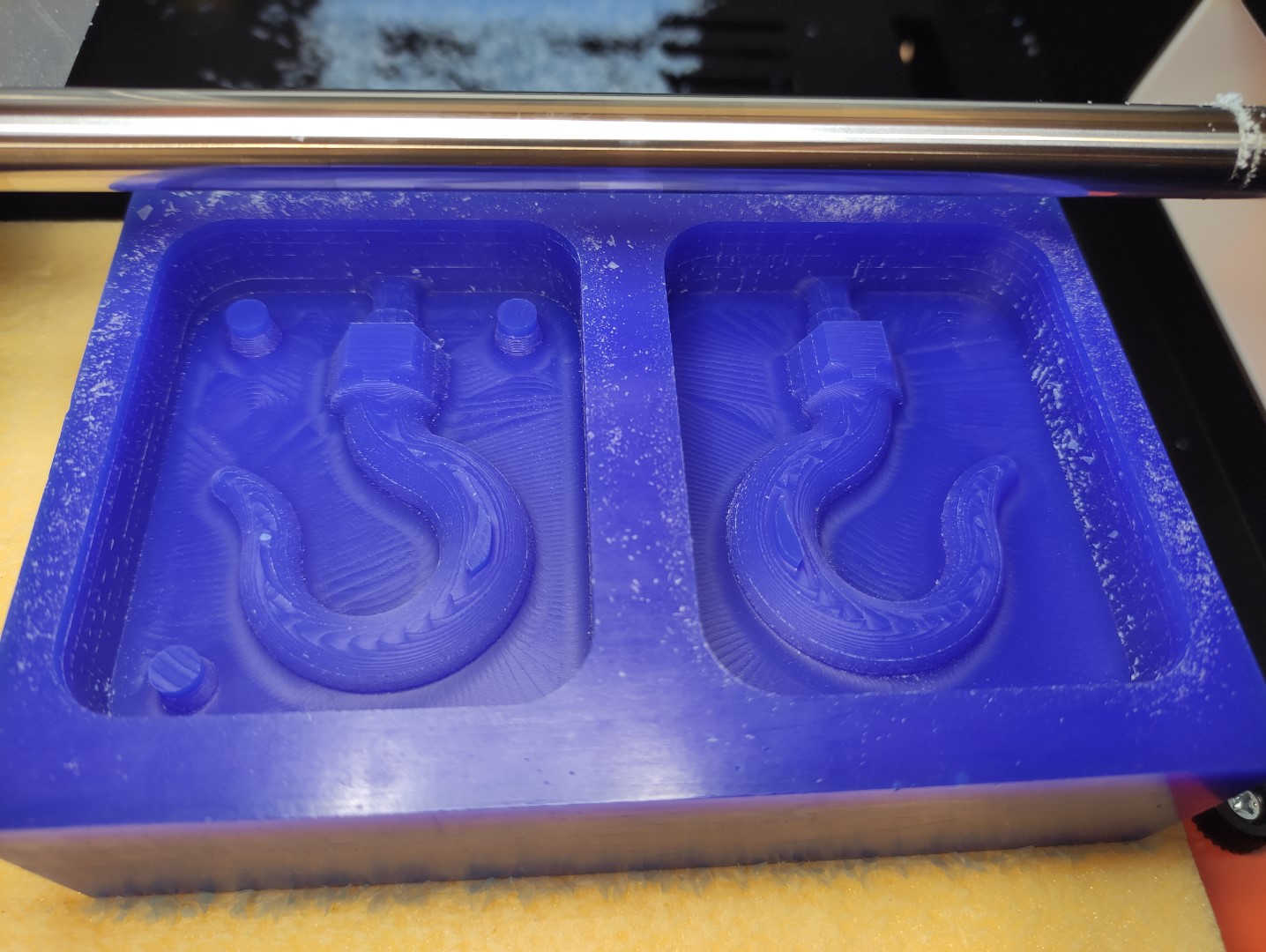
-
Pre-finish Cut:
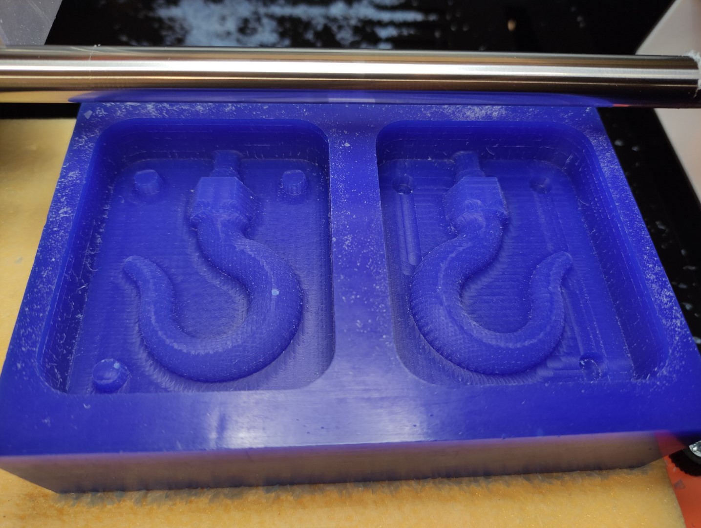
-
Finish Cut:
Some noticeable scratches were made done while vacuum cleaning. 😒
I think that it’s worth mentioning that this is rather a dirty process, often cleaning is recommended.
Casting
Materials
I used different materials (find attached their datasheets in the Files section).
For all of the following materials it’s recommended to work in a well ventilated area, and wear gloves due to irritation risks.
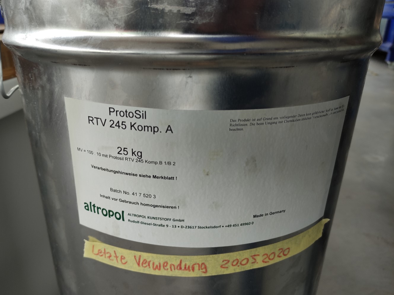
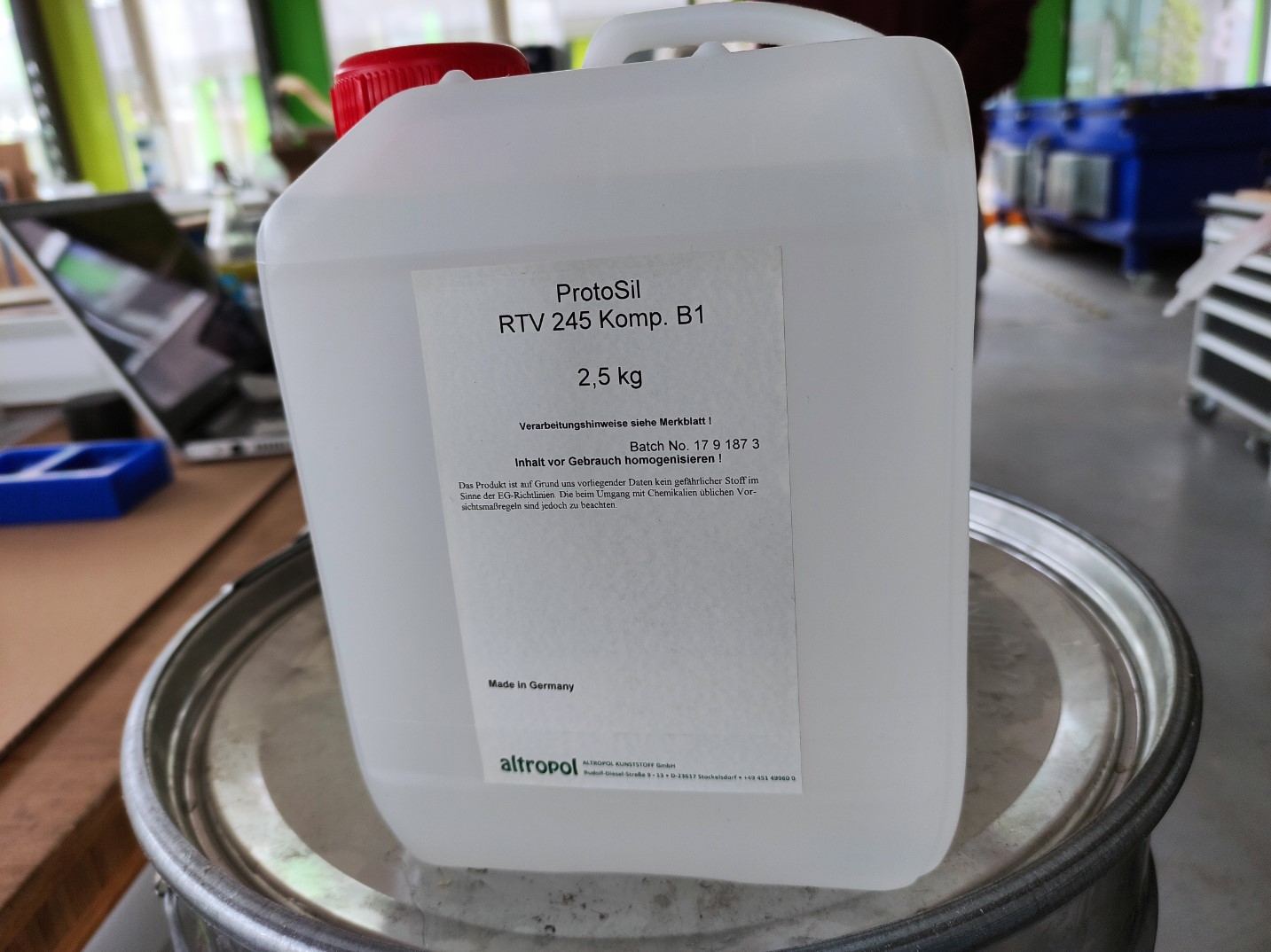
ProtoSil RTV 245
Reviewing safety datasheet
-
First of all, we can see the materials with which it can be mixed and the ratios:
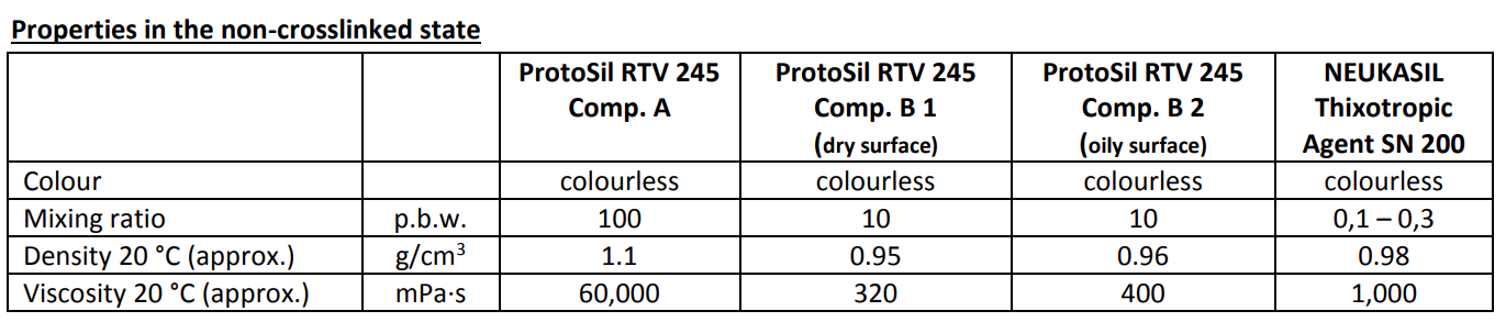
In this FabLab we had the ProtoSil RTV 245 Comp. A and the ProtoSil RTV 245 Comp. B 1 (dry surface) -
Secondly, we have the Properties of the mixture:
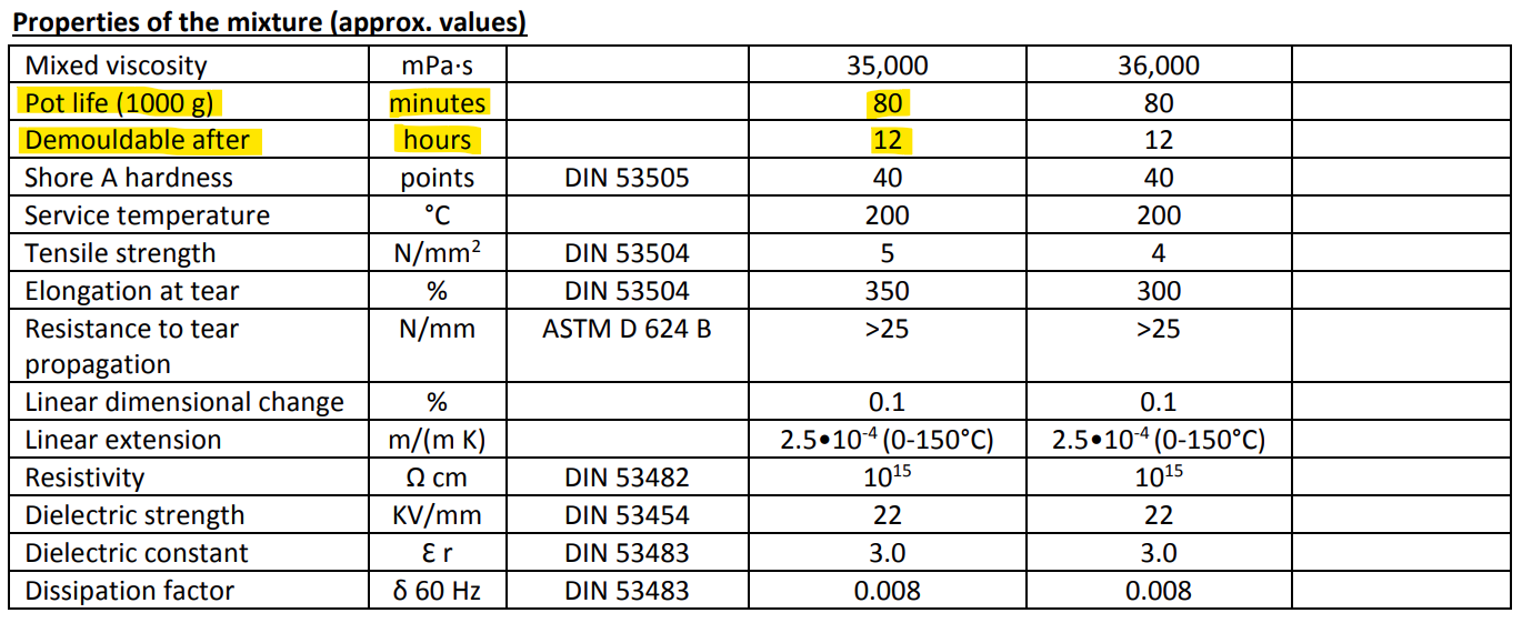
In this case, the most important properties were Pot life (80mins) and Curing time (12h). -
Then, we have the instructions to process the material.
-
At the bottom we have the Storage data:
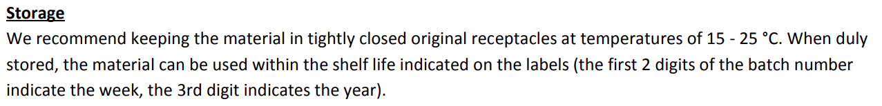
It is recommended to keep this material closed in its original container at a temperature of 15 to 25°C.
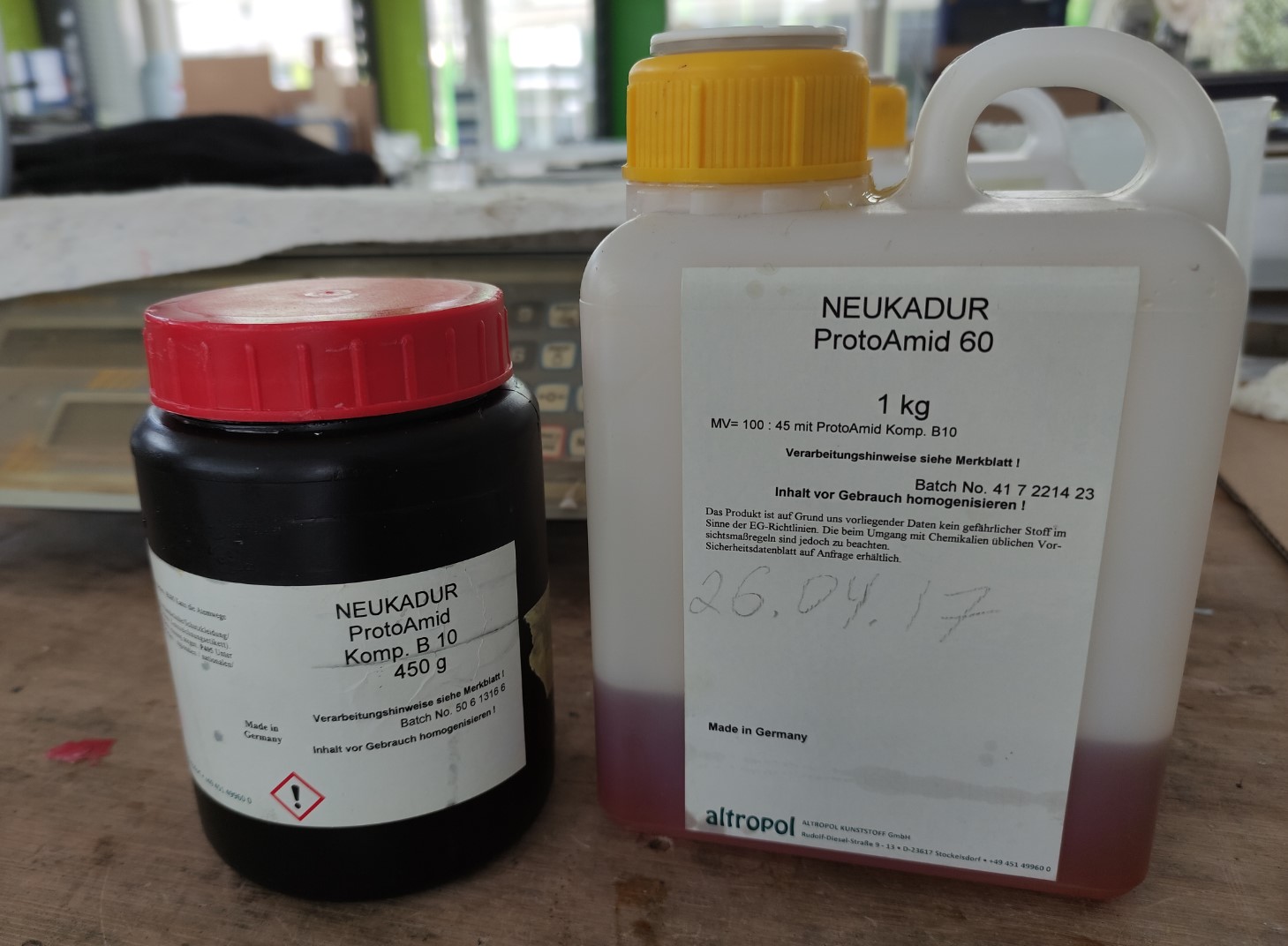
NEUKADUR ProtoAmid 60
Reviewing safety datasheet
-
First of all, we can see the materials with which it can be mixed and the ratios:
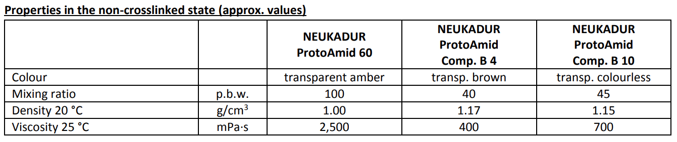
In this FabLab we had the NEUKADUR ProtoAmid 60 and the NEUKADUR ProtoAmid Comp. B 10. -
Secondly, we have the Properties of the mixture:
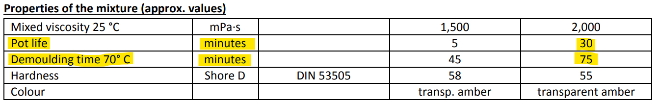
In this case, the most important properties were Pot life (5mins) and Curing time (45mins). -
Then, we have the instructions to process the material.
-
At the bottom we have the Storage data:
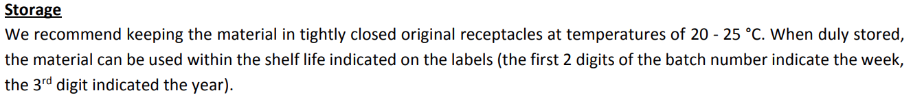
It is recommended to keep this material closed in its original container at a temperature of 20 to 25°C.
NEUKADUR ProtoCast 105
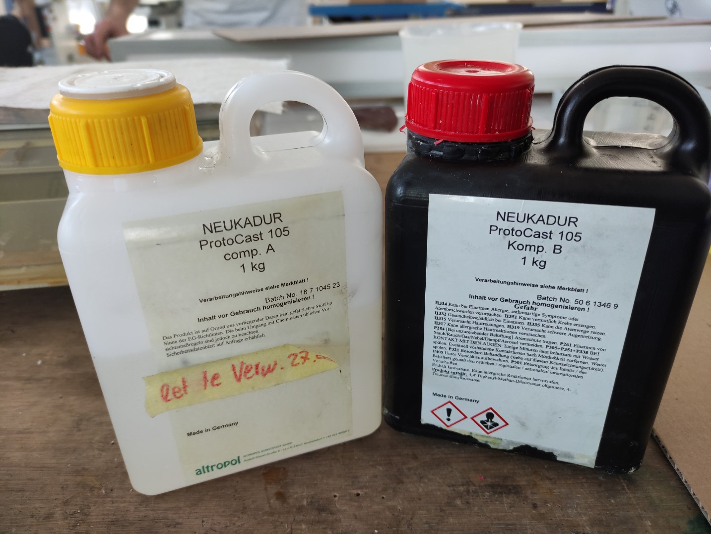
-
First of all, we can see the material with which it can be mixed and the ratio:
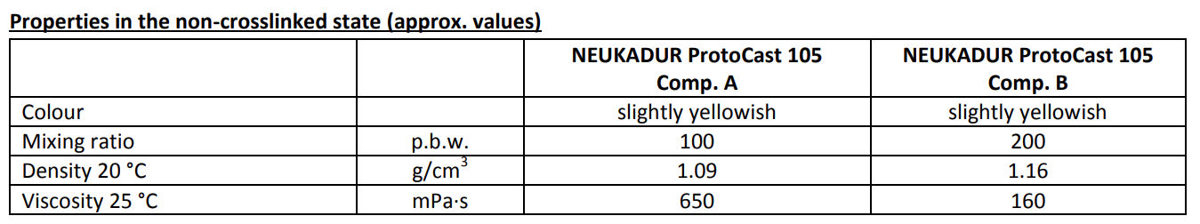
-
Secondly, we have the Properties of the mixture:
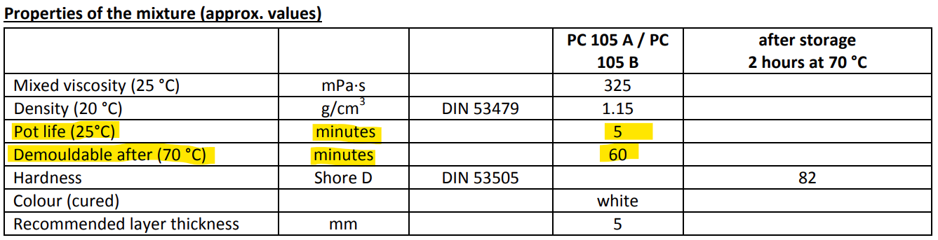
In this case, the most important properties were Pot life (80mins) and Curing time (12h). -
Then, we have the instructions to process the material.
-
At the bottom we have the Storage data:
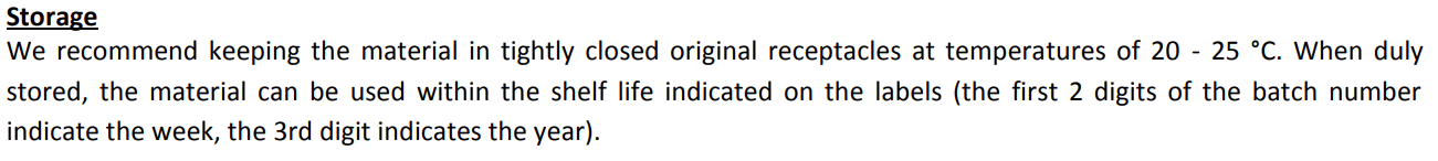
It is recommended to keep this material closed in its original container at a temperature of 20 to 25°C.
Tools
Vacuum machine
According to the instructions of each material, a vacuum step step is needed.
Schüchl UHG-500 Easy vacuum casting machine:
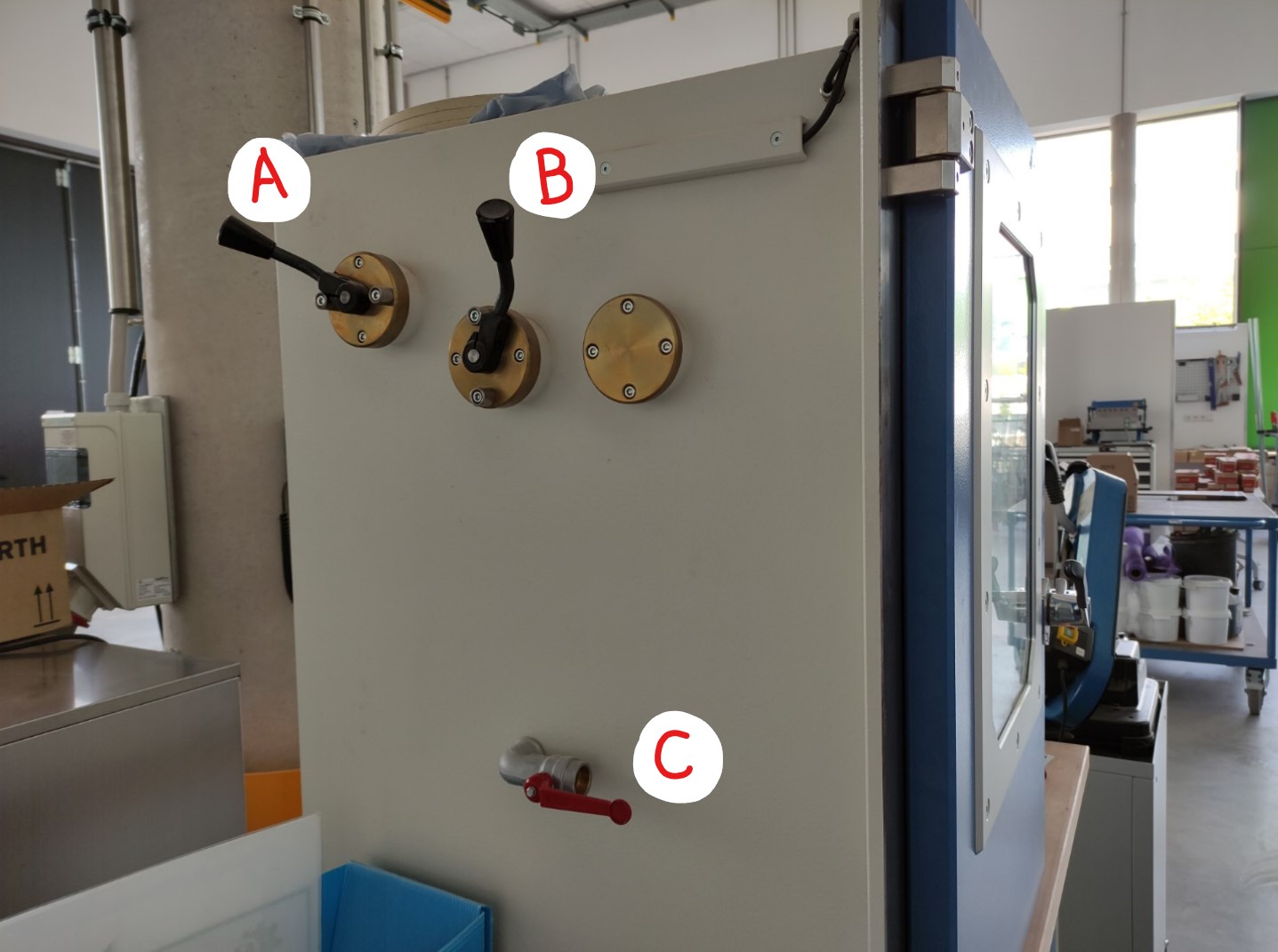
A) Hand lever, to tilt component B.
B) Hand lever, to tilt component A.
C) Vacuum release valve.
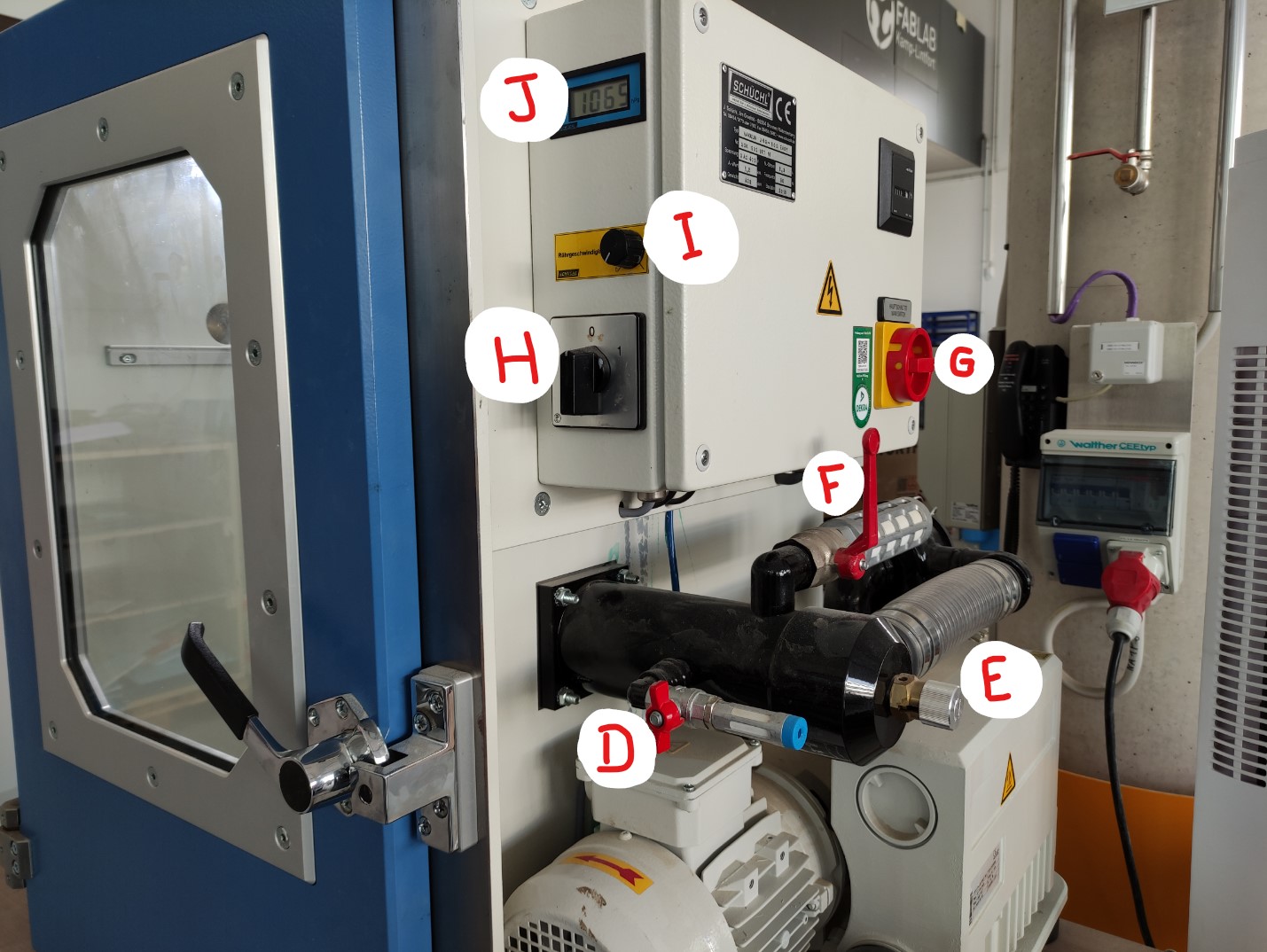
D) Mix pressure valve, simplified the adjustment.
E) Vacuum regulation valve, for variable vacuum.
F) Chamber aeration, to flood the vacuum chamber.
G) Main power switch (ON/OFF).
H) Vacuum switch (ON/OFF).
I) Mixer speed: variable mixer speed controller.
J) Vacuum display.
Video: Component B been poured into Component A under vacuum.
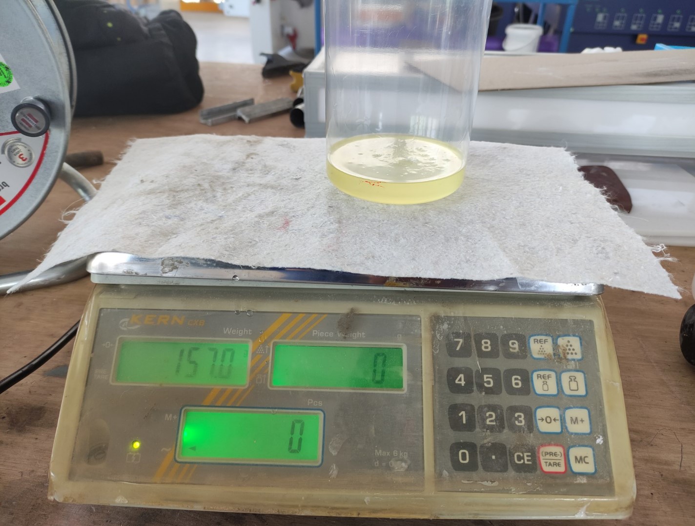
Scale
According to the instructions of each material, exact proportions of components are needed for the mixes, then for that we used a scale.
Extra support
- Clamps, to keep the mold together during casting.
- Compressed air, to clean containers and molds.
Casting the Mold
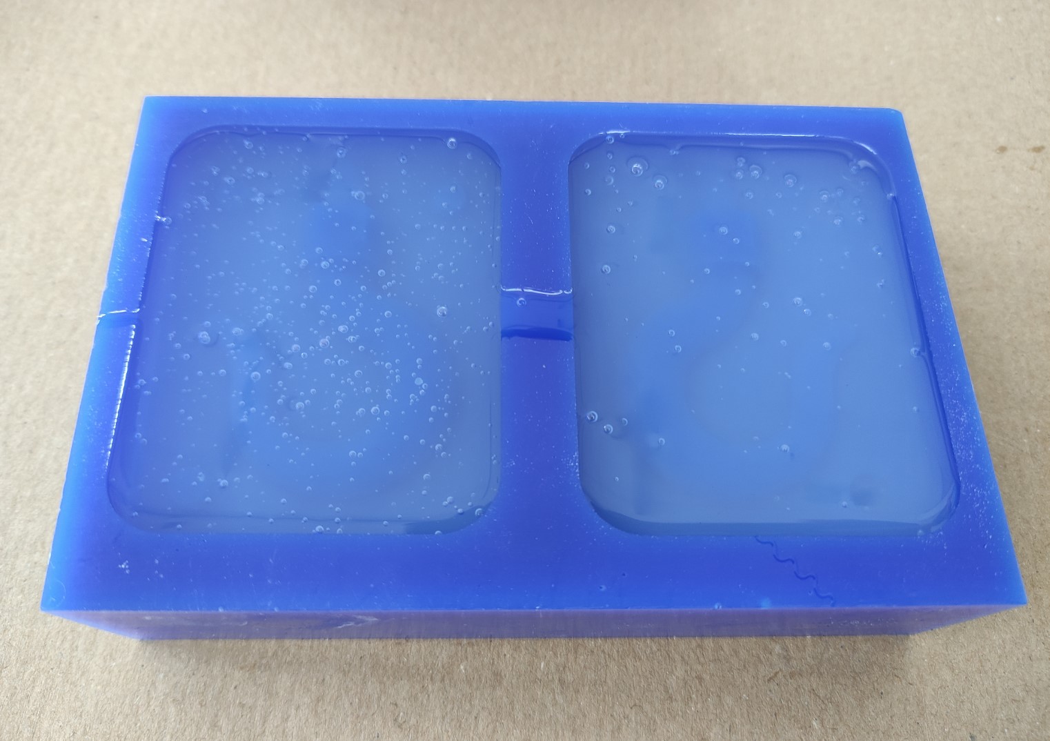
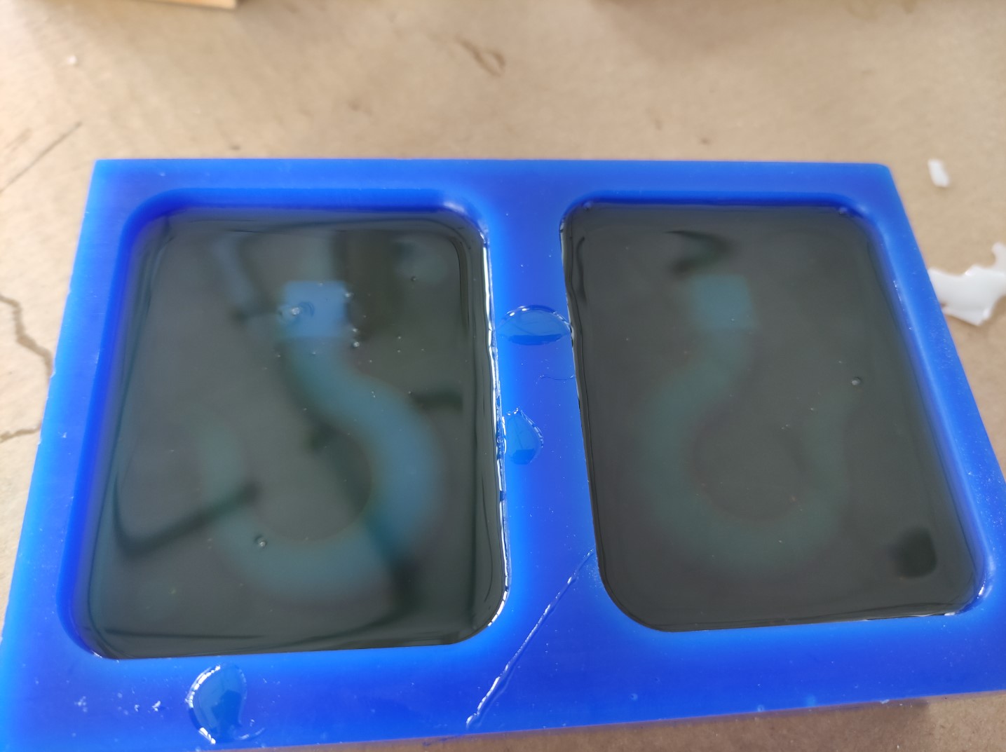
ProtoSil RTV 245:
-
When the mix was just poured, it had a lot of bubbles; It’s ok since they will come out during the drying time:
-
According to the material instructions, it takes 12h to dry out completely, in this case I went back to the lab after ~20h:
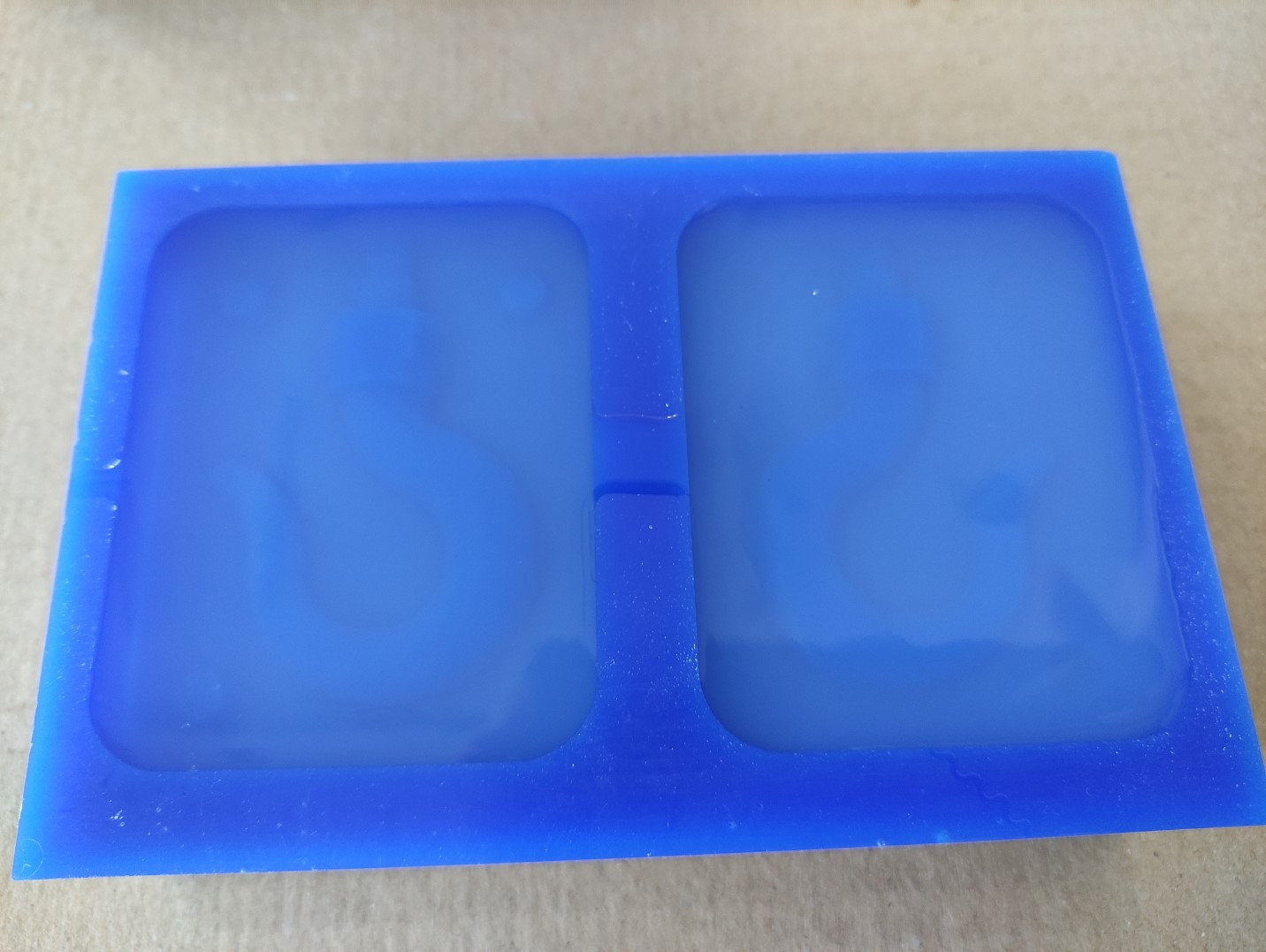
-
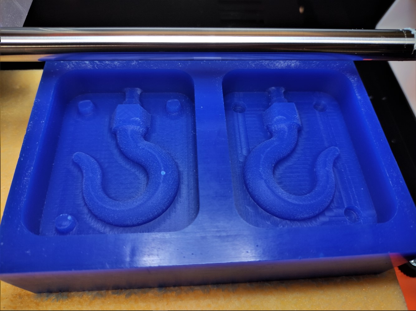
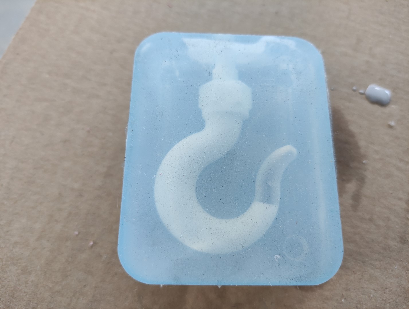
Demolded:
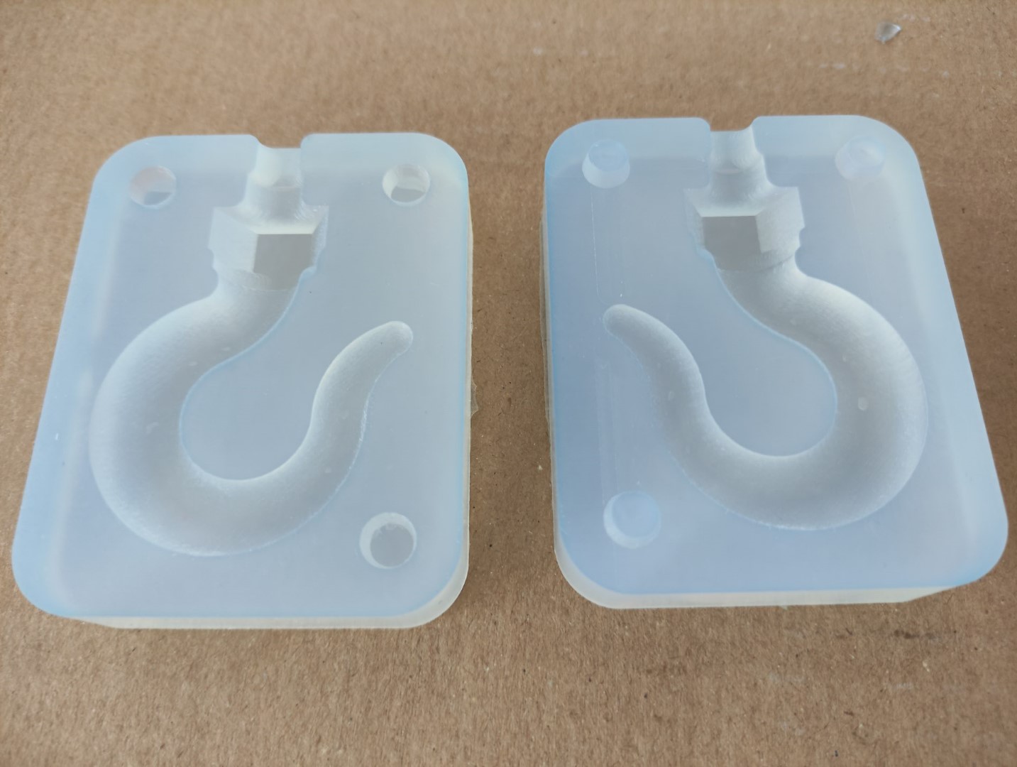
NEUKADUR ProtoAmid 60:
-
Material just poured:
-
Even when the instructions indicate a drying time of 75mins, I demolded it after 3h20m, but it was really hard to take out. The result was a useless mold and also a pin from the wax was destroyed:
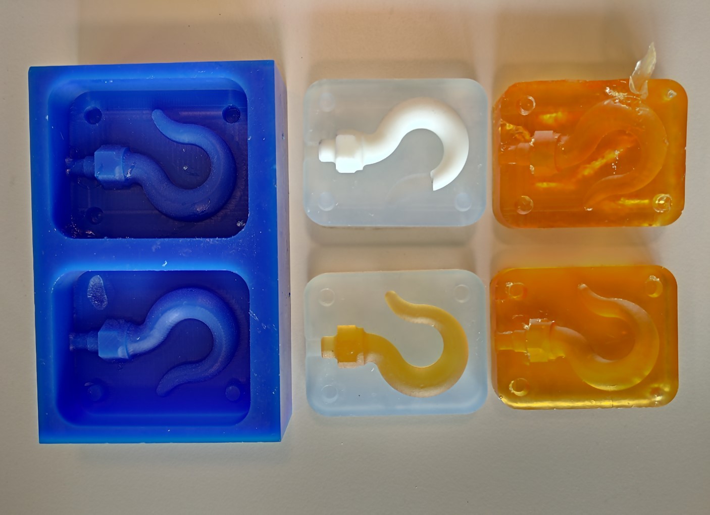
Casting the Model
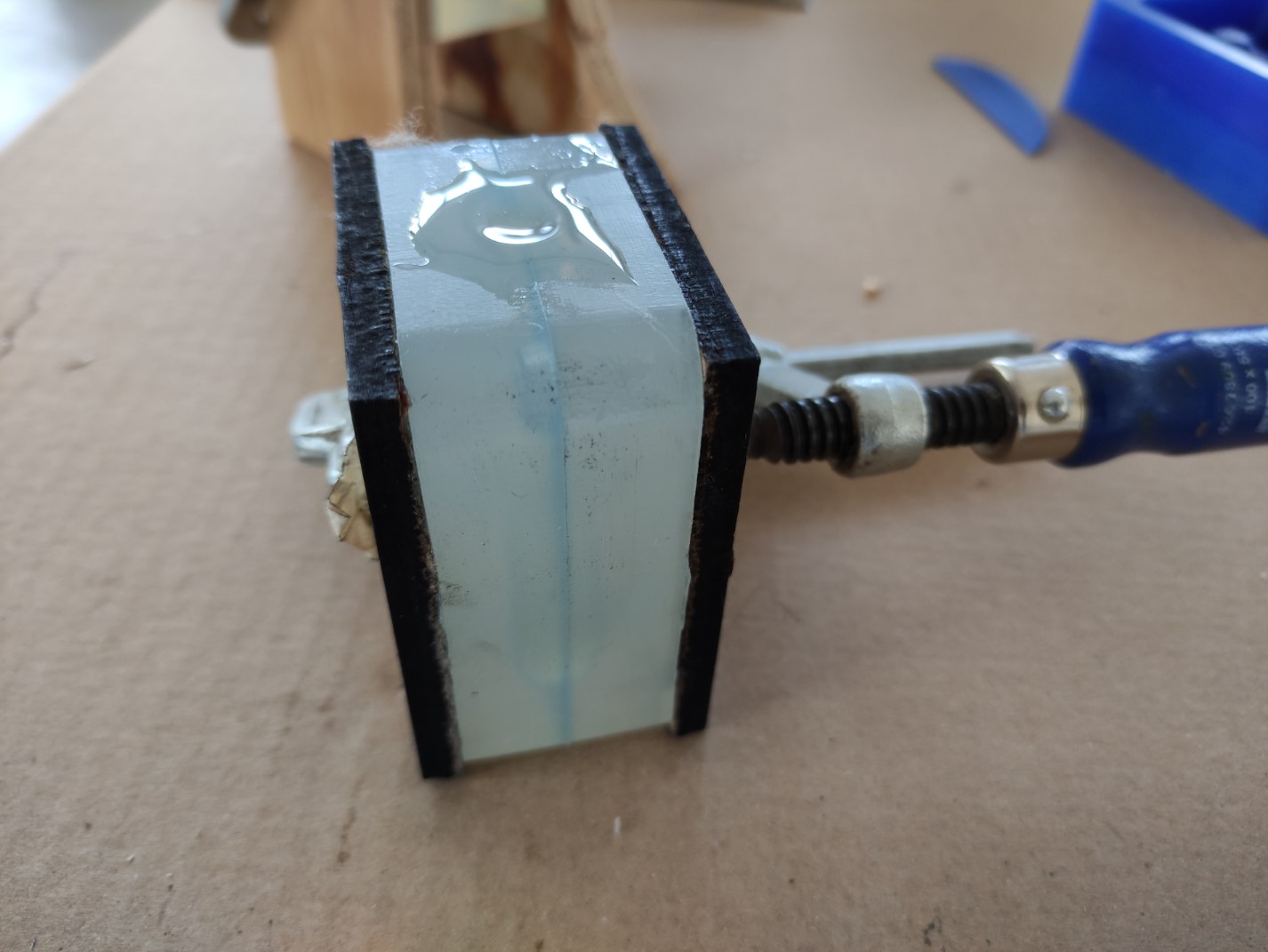
NEUKADUR ProtoCast 105:
In this case, since it’s not an “open” mold, but a two-piece mold, it’s needed keep them together using a rope or a clamp, using some extra hard material sheets.
-
Material just poured:
-
Just in this moment I noticed that, due to the shape of my model, I had to make another hole to release air from the tip of the Hook when pouring the material:
-
Demolded:
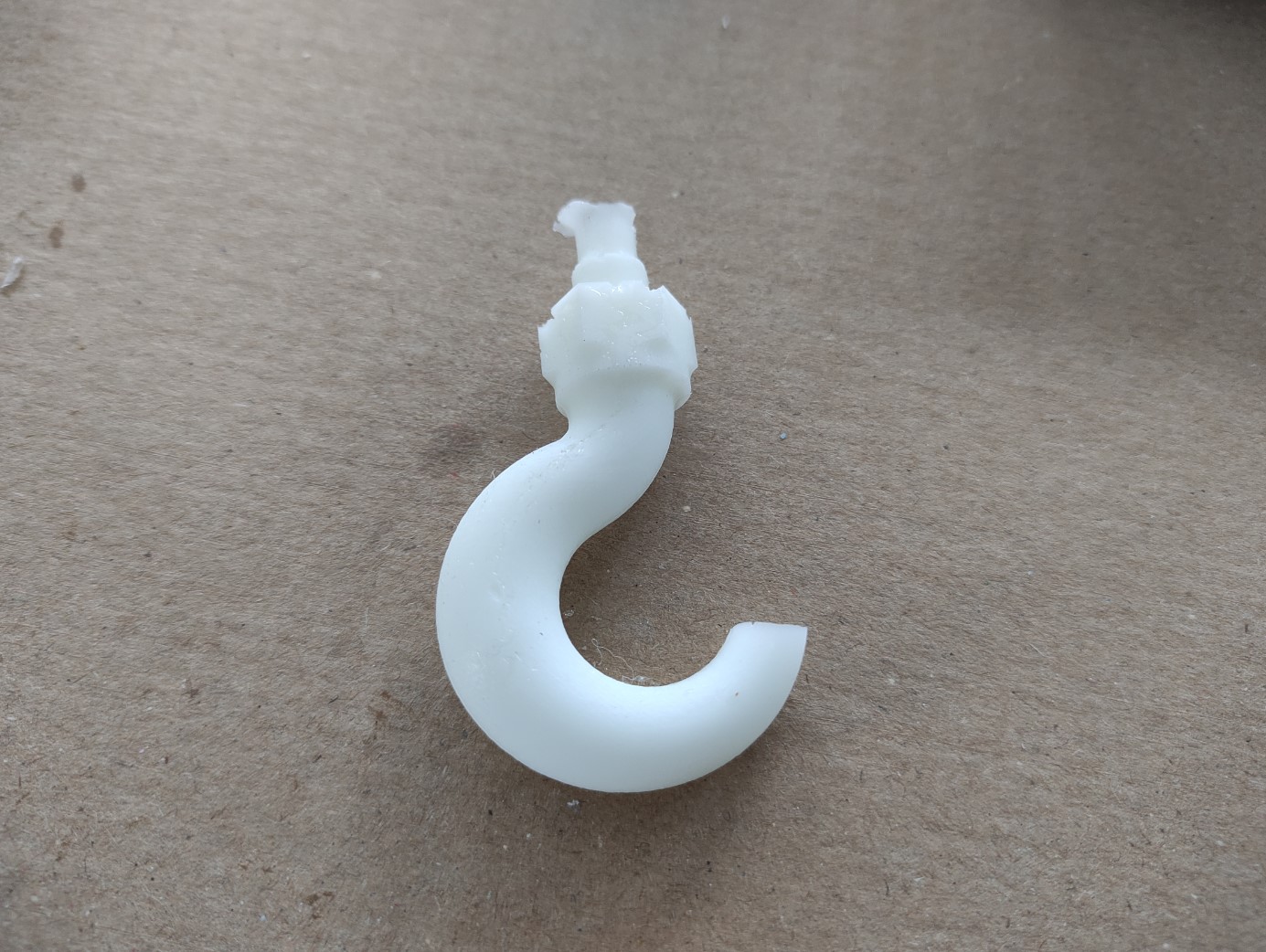
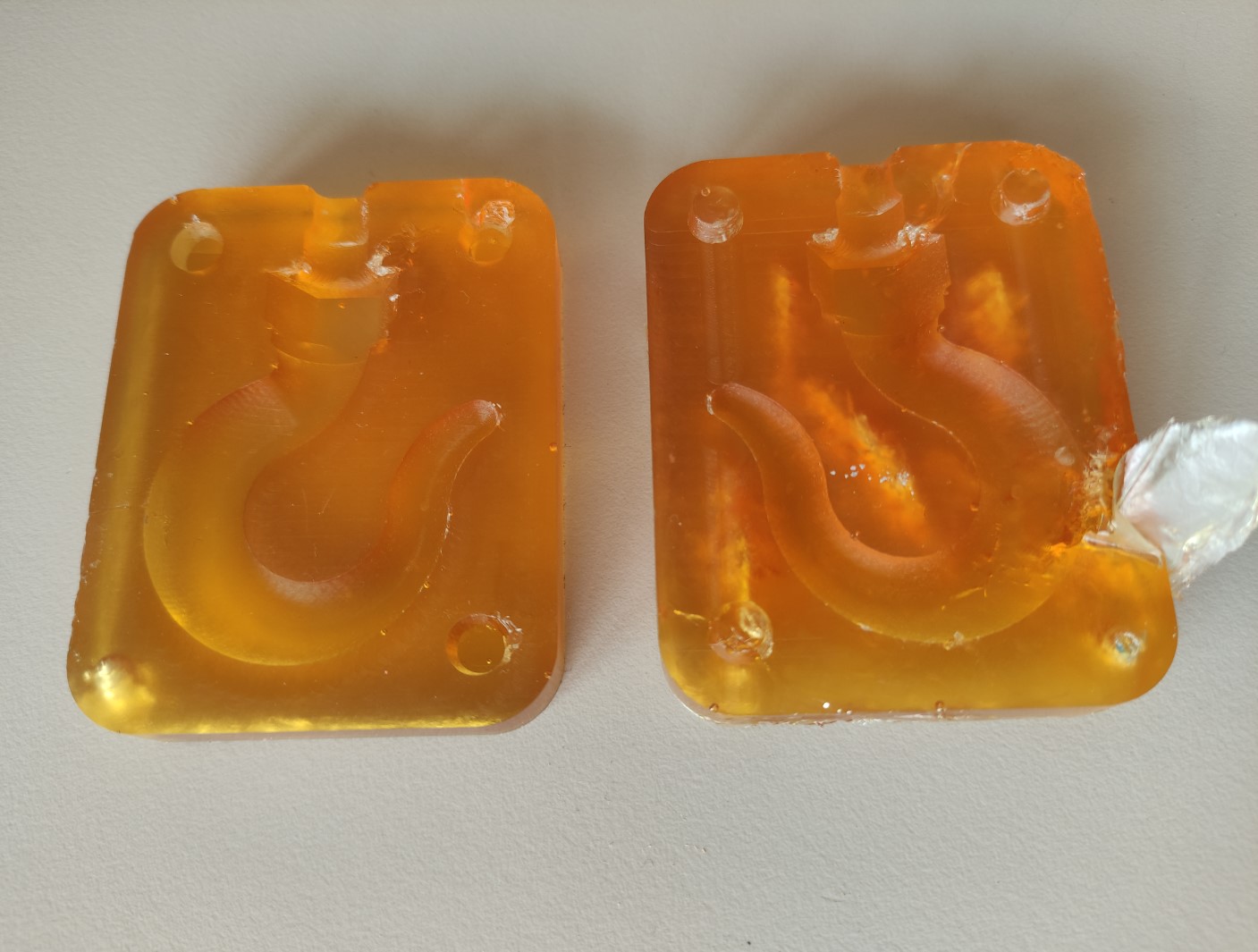
NEUKADUR ProtoAmid 60:
-
To avoid the problem that I had with the ProtoCast 105, of the air in the tip, I used a syringe to suck put the air in it; I also used this time acrylic pieces from the trash, so I can completely see how it was going:
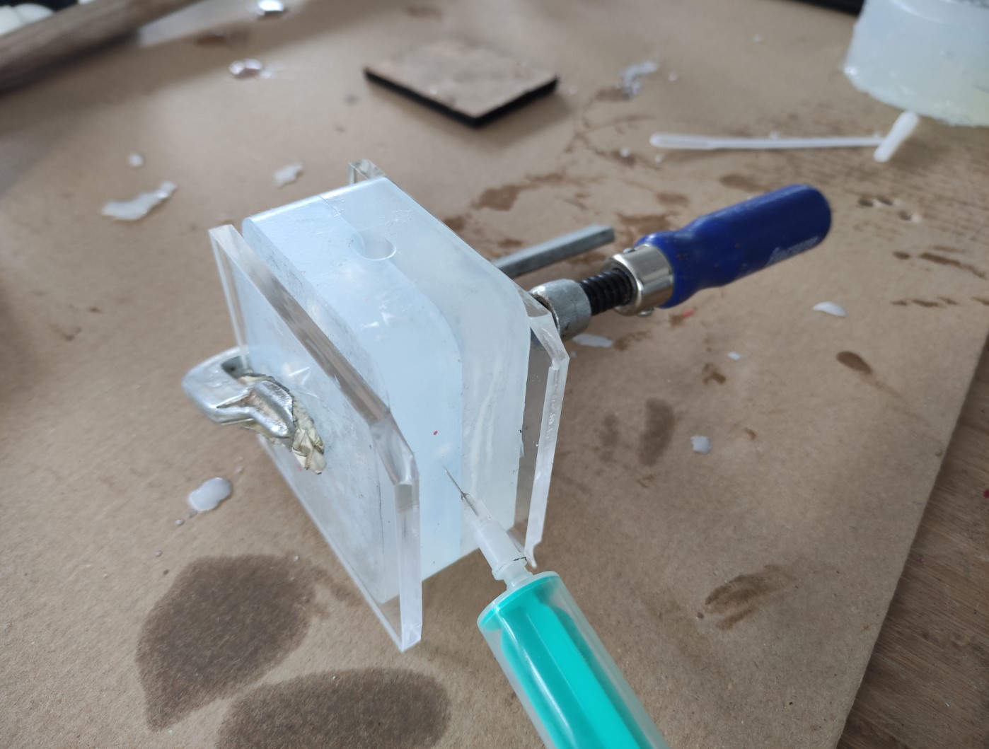
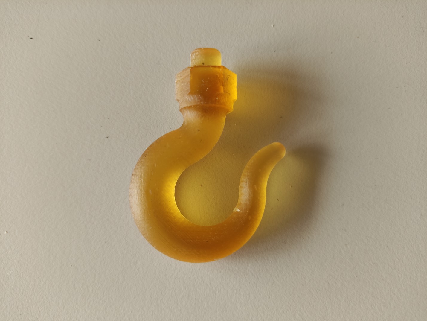
-
Even when the instructions indicate a drying time of 75mins, I demolded it after 3h20m and. Unlike the mold made out the same material, the model resulted easy to take out and looks very nice. Extra parts were filed:
Files and references
- Hook - 3D model
- Hook mold - 3D model
Support documentation
- Albot Dima. 2017. Molding and casting. FabLab KampLintfort
- Hashim Al Sakkaf. 2017. Molding and casting. FabLab Dubai
Datasheets
- NEUKADUR ProtoAmid 60
- NEUKADUR ProtoCast 105
- ProtoSill RTV 245