- Robot
Circuit
This section has been pre-worked during my Output devices and Embedded Networking and Communications assignments.
Components:
- Microcontroller board:
1x Fab-OmniBot board, whose documentation is in the next section:
- Input devices:
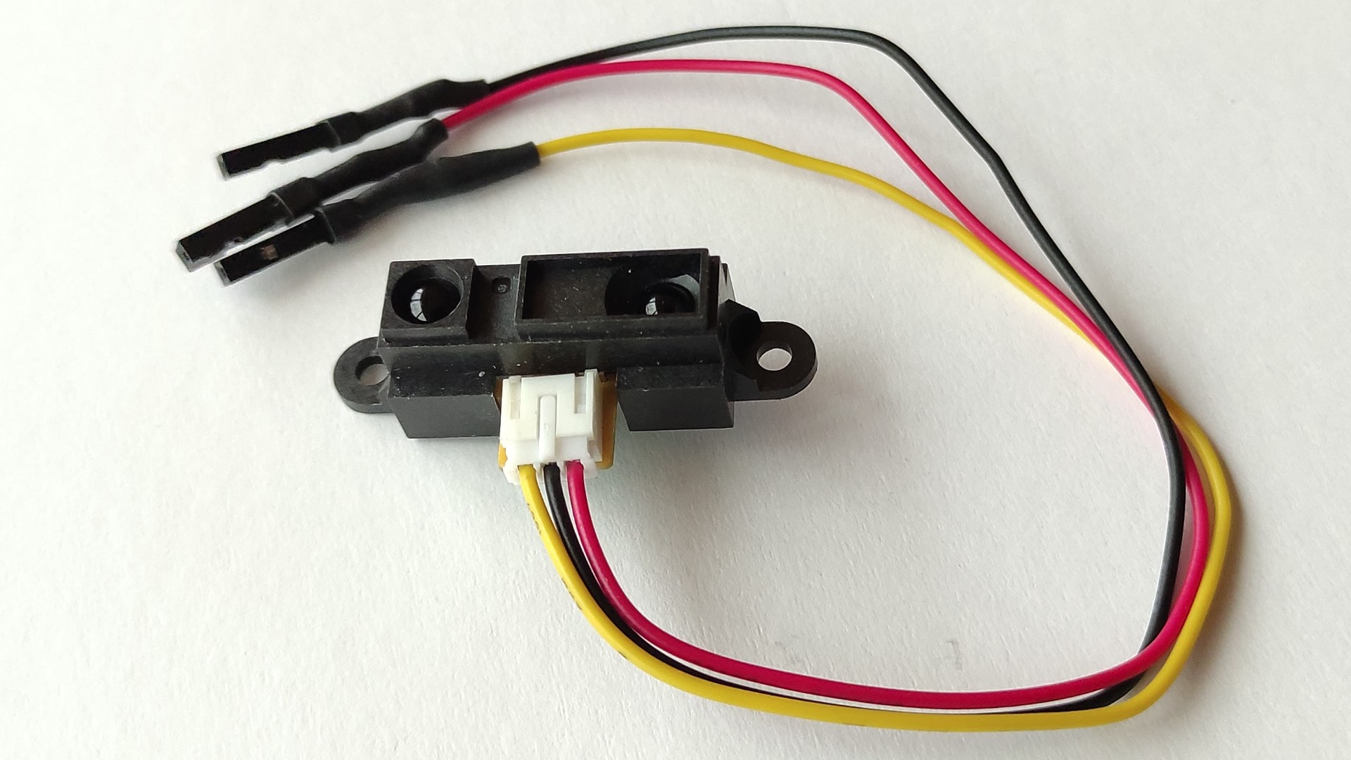
Since I wanted to add a collision avoidance property, I have added a distance sensor. The basic sensor that most people use for projects like this one is the ultrasonic sensor but, since it has the precision problem on irregular surfaces, I chose an infrared sensor cause it has a better performance in these situations.
1x GP2Y0A21YK which is a Grove - 80cm Infrared Proximity Sensor:
- Output devices
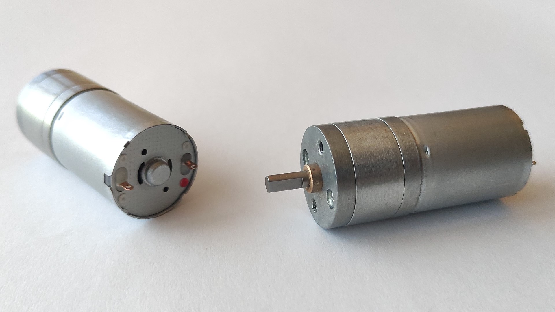
3x JGA25-370 12V geared DC motor, 350RPM, 1.4Kg*cm:
- Wireless communication:
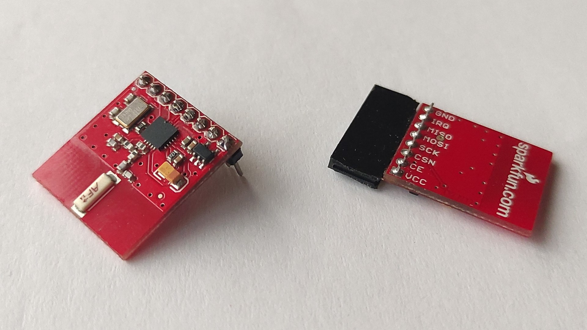
1x nRF24 module: this one has the antenna on board; I have also replaced the pin header to adapt it to me needs/idea:
- Power:
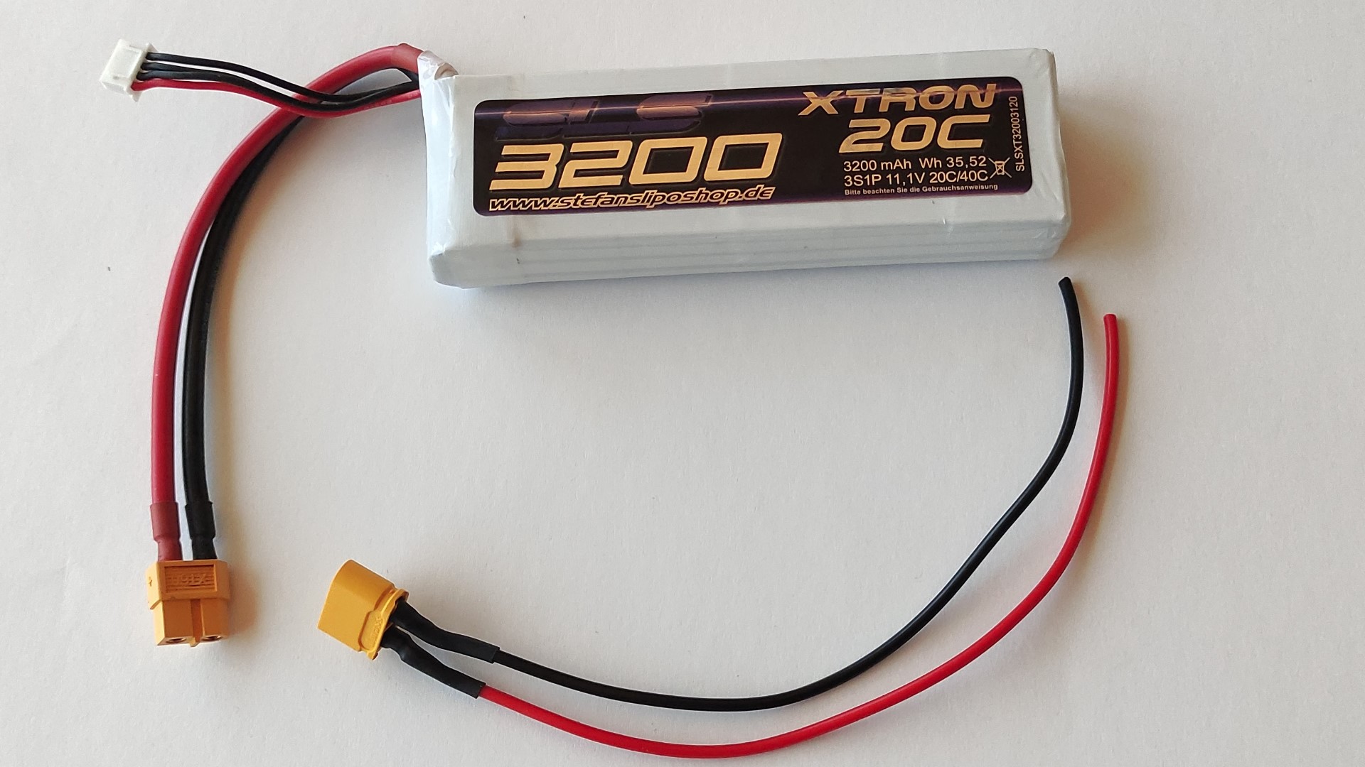
1x 3S Lipo Battery 3200mAh 11.1V:
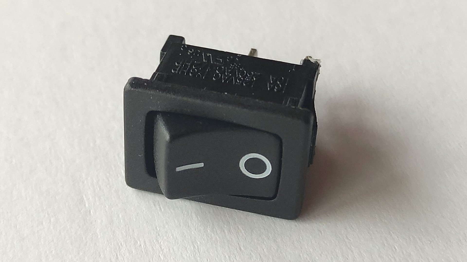
1x On/Off switch:
Fab-OmniBot board
Requirements, considerations and component selection:
It’s worth mentioning first that I wanted all of the boards for my final project to be double sided.
- I used an ATtiny3216 microcontroller cause it has the necessary pins and memory for this application.
Image taken from SpenceKonde.
- I used a nRF24 module for communication, then I have arranged pin headers for connecting this module.
- A 3.3V voltage regulator (since the nRF24 module works at 3.3V, the laser sensor can work at 3.3-5V, and also the ATtiny3216 can work at that voltage).
- 1uF capacitor for microcontroller voltage stabilization.
- A LED (with a 499Ω resistor) to indicate that the board is getting energy.
- 220uF capacitor for microcontroller voltage stabilization.
- UPDI + VCC + GND connection for programming and powering my board.
- FTDI connection to see the serial monitor.
- I have used the footprint of TH pin headers for the laser sensor.
- L298 motor drivers.
- Screw terminals to connect the battery and the motors.
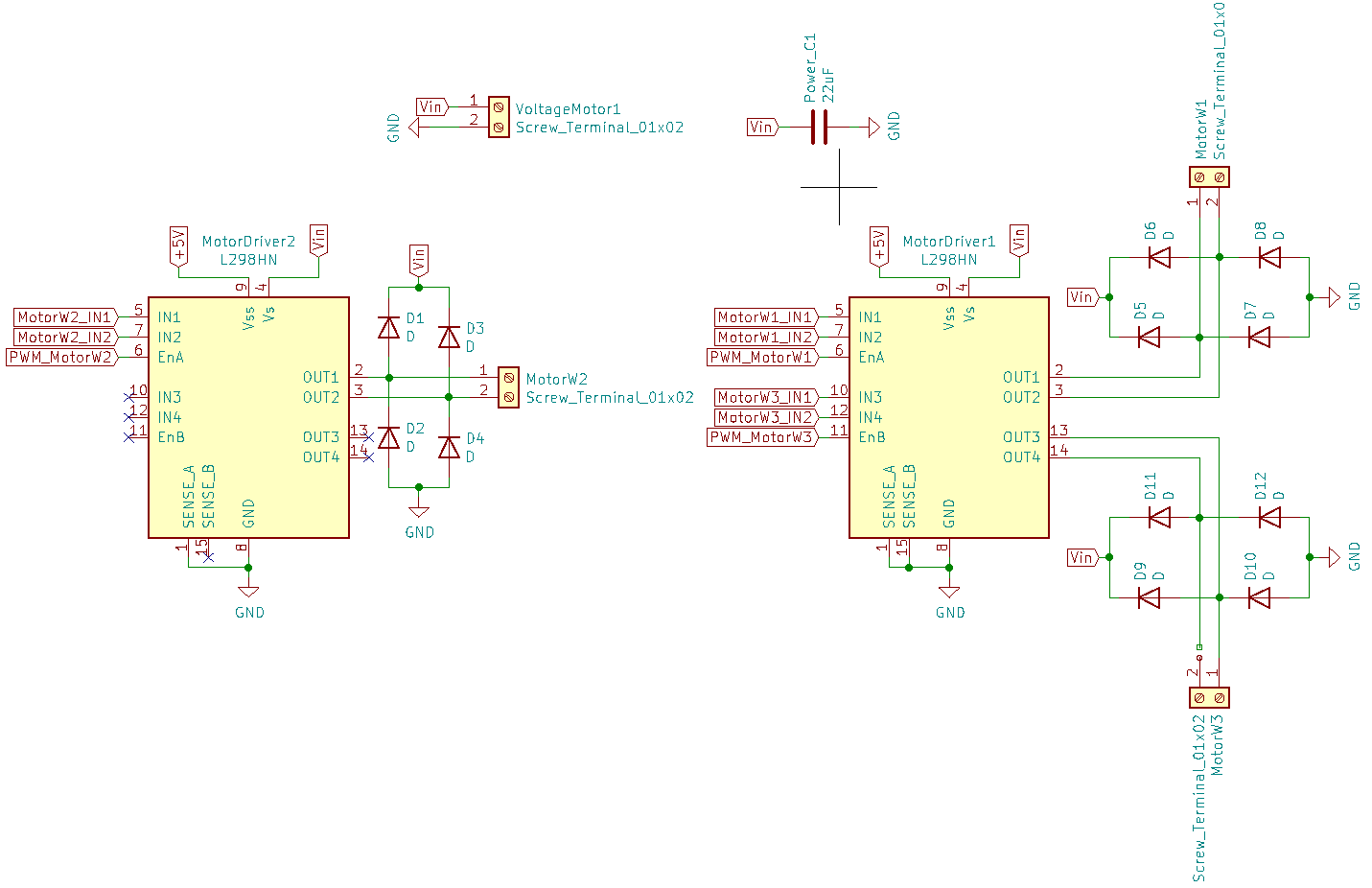
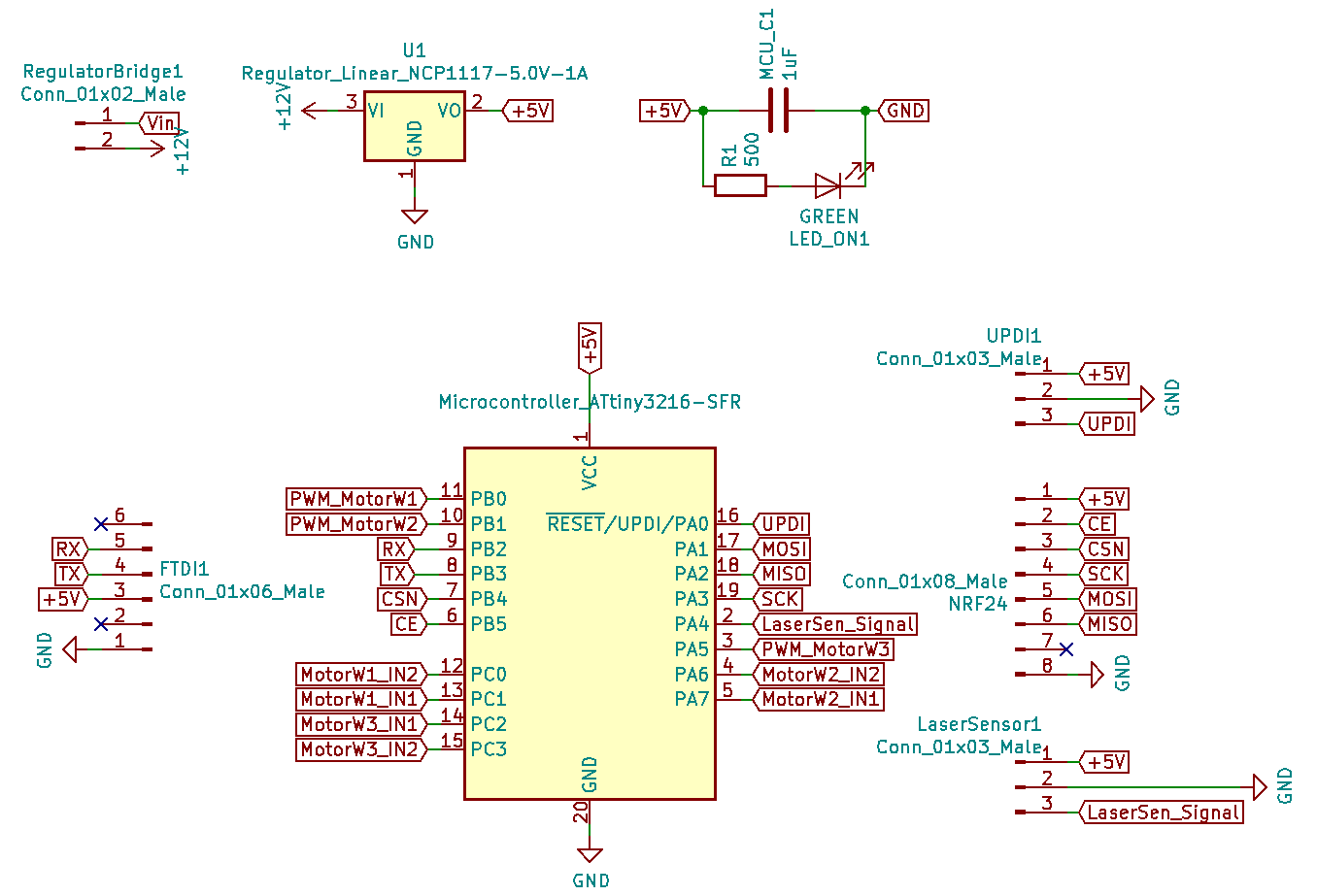
Schematic
For electronics design I have used KiCad.
Board layout
- I added here vias.
- I kept most of the components on the front layer.
- I put the terminal screws, power capacitor, and voltage regulator on the back layer.
-
Front side:
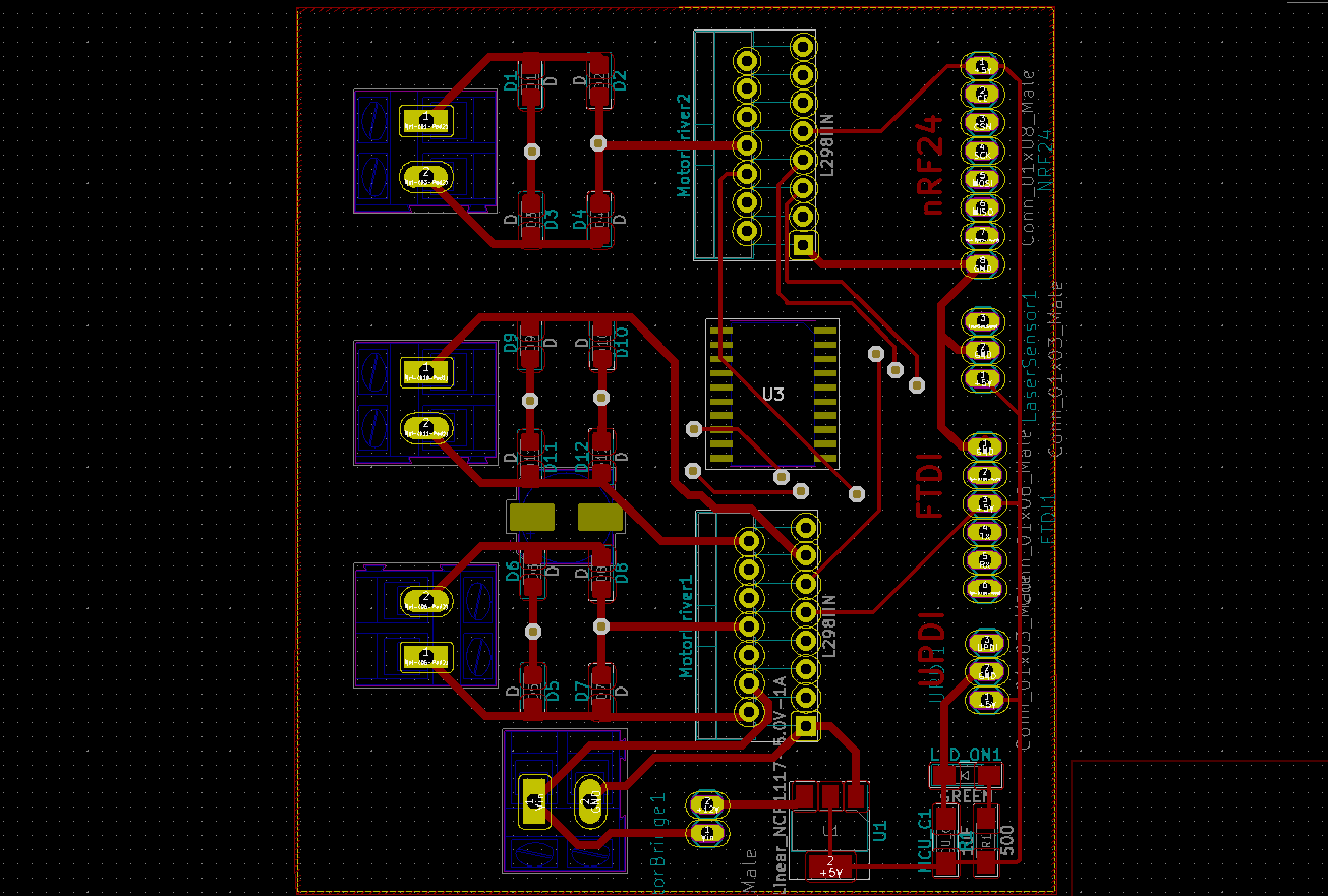
-
Back side:
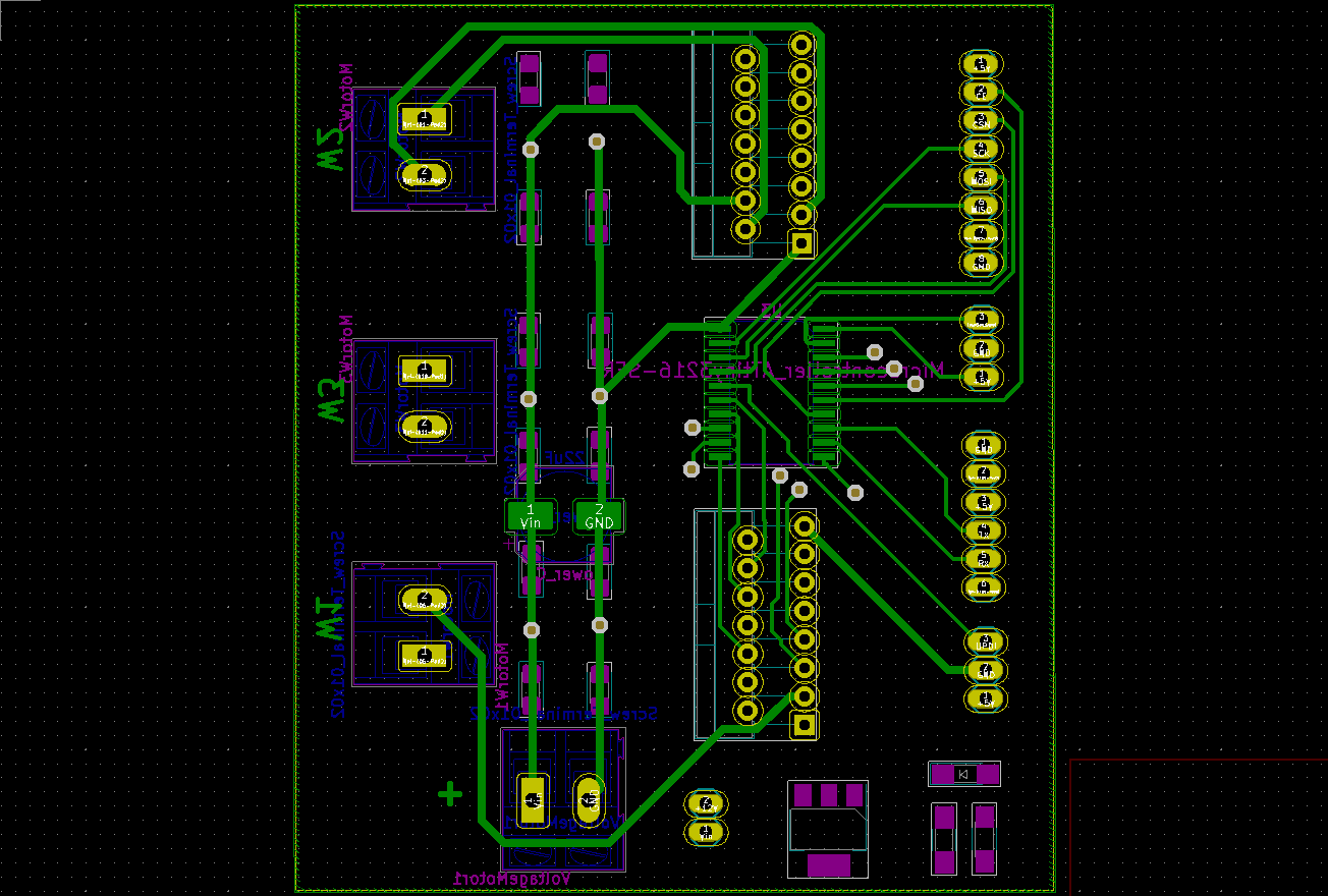
Eventually I have used “Add filled zones” as GND.
I have exported the images as SVG, then I prepared them using Inkscape and GIMP and exported them as PNG with DPI=1500.
Milling
I have manufactured the by milling.
Images:
I have milled the front side first, where I cut the outline:
- Traces:
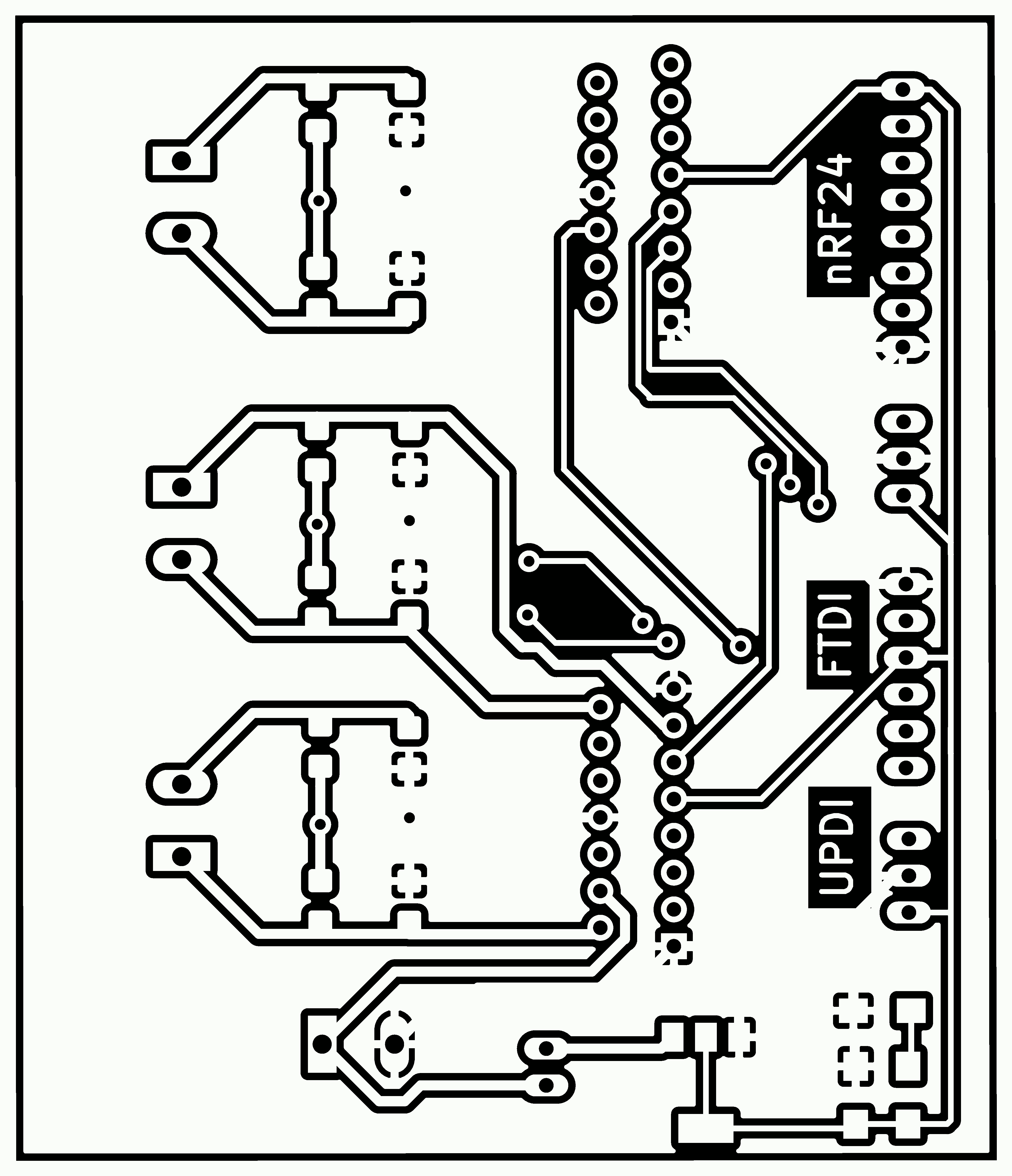
- Outline:

Eventually I milled the back side, where I drilled the holes:
- Traces:
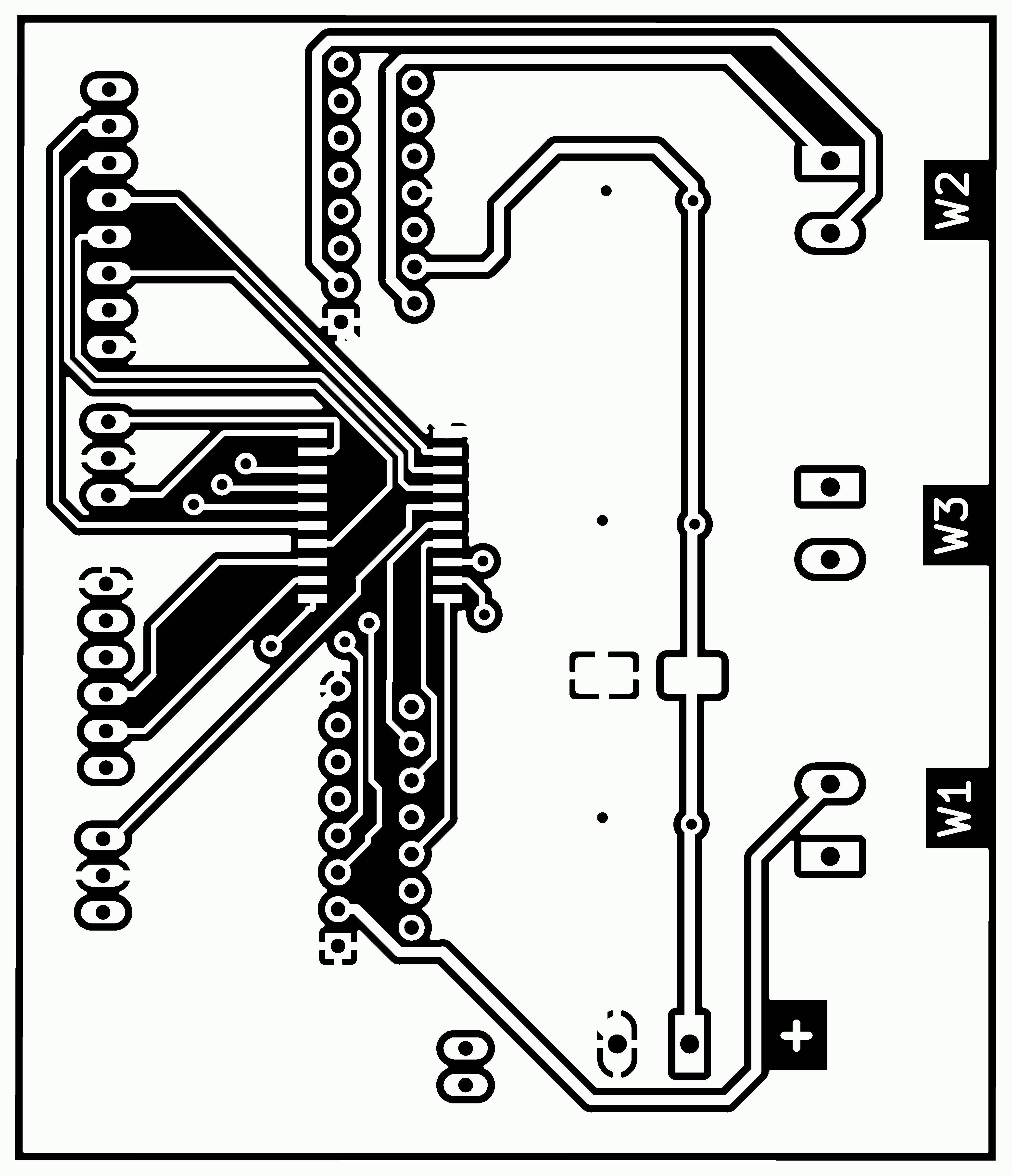
- Holes:

Afterwards I have generated the g-code using FabModules.
Milling process:
- The milling machine I used was the Roland MonoFab SRM-20.
- The tool I used was a V-bit 0.2-0.5mm.
- The double sided PCB was FR1.
Soldering
List of Components:
| Qty | Component |
|---|---|
| 1 | ATtiny3216 microcontroller |
| 1 | ZLDO1117G33TA 3.3v voltage regulator |
| 2 | L298N motor driver |
| 12 | A7 diodes |
| 1 | 220uF capacitor |
| 1 | 1uF capacitor |
| 1 | 499Ω resistor |
| 1 | LED |
| 20 | Single row right-angle male pin header |
| 2 | Single row straight male pin header |
| 4 | Screw terminals 1x2 |
| 14 | 0.6mm rivets |
| - | Cables |
- I have added some FLUX SK 10 as a final protective layer.
Programming
Preparation
First settings
For the first time we need to add the MegaTinyCore to the Arduino IDE:
- Open the Arduino IDE.
- File > Preferences
- Paste the following link in Additional Boards Manager URLs: http://drazzy.com/package_drazzy.com_index.json
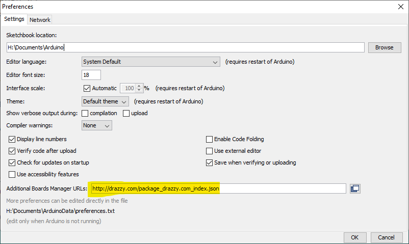
- Press OK
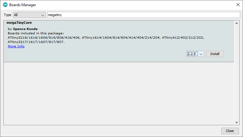
- Tools > Board > Boards Manager
- Search for _MegaTinyCore (by Spence Konde):
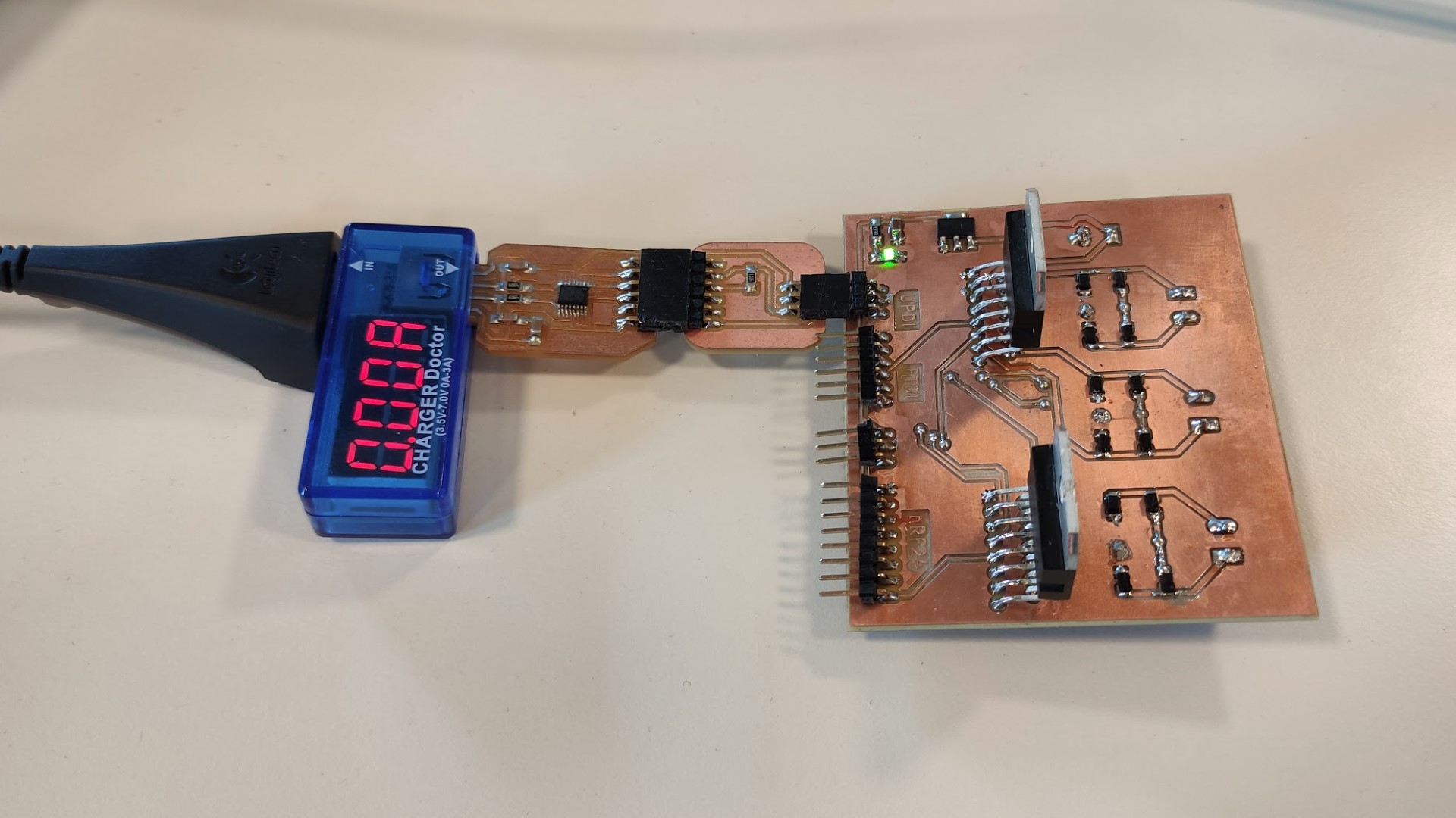
Connecting board to PC
For programming the board I used the USB and FTDI-UPDI adapter boards that I made during the Electronics production assignment:
Upload a Code
-
To upload a code to the Board, we just need to use the following highlighted settings in the Arduino IDE:
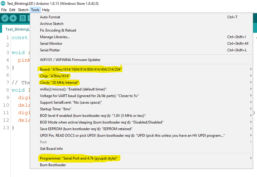
-
After selecting these options and when using the microcontroller by the first time, press Burn Bootloader to setup the Microcontroller; then you can just press the Upload button:

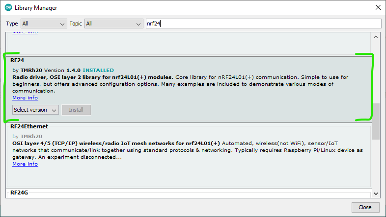
Download libraries:
Beforehand, it’s needed to install nRF24 (by TMRh20):
Code block
1 2 3 4 5 6 7 8 9 10 11 12 13 14 15 16 17 18 19 20 21 22 23 24 25 26 27 28 29 30 31 32 33 34 35 36 37 38 39 40 41 42 43 44 45 46 47 48 49 50 51 52 53 54 55 56 57 58 59 60 61 62 63 64 65 66 67 68 69 70 71 72 73 74 75 76 77 78 79 80 81 82 83 84 85 86 87 88 89 90 91 92 93 94 95 96 97 98 99 100 101 102 103 104 105 106 107 108 109 110 111 112 113 114 115 116 117 118 119 120 121 122 123 124 125 126 127 128 129 130 131 132 133 134 135 136 137 138 139 140 141 142 143 144 145 146 147 148 149 150 151 152 153 154 155 156 157 158 159 160 161 162 163 164 165 166 167 168 169 170 171 172 173 174 175 176 177 178 179 180 181 182 183 184 185 | |
Frame
Design
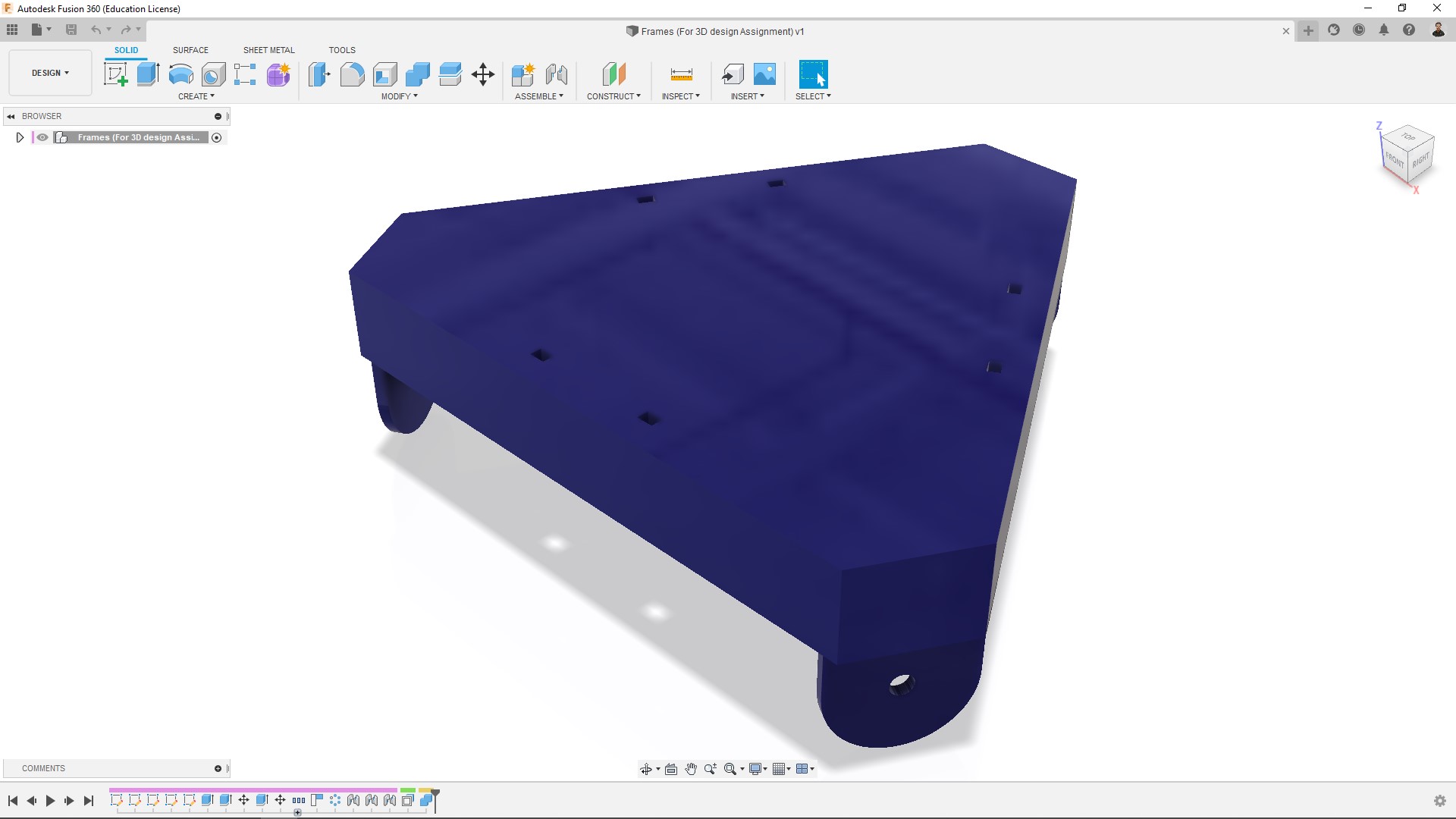
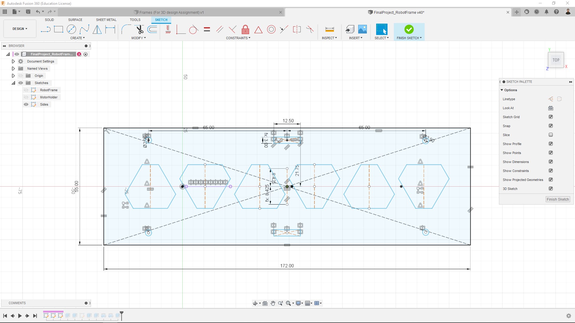
For designing I used Fusion 360.
This step took longer than expected… between re-designing and laser cutting prototypes:
-
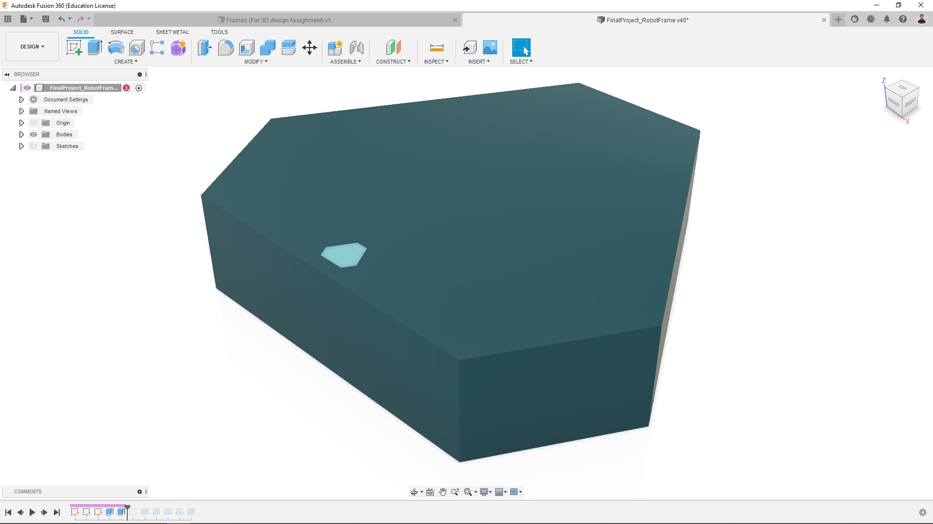
This is the very first model that I had:
-
Then I thought about packing everything inside, so the motors will be in the middle of the frame. At this point I already had also printed the final version of the wheels:
It doesn’t have the holes for the motors cause it’s just a reference model, I made those details in 2D later.
Then I started making the 2D parts and laser cutting some tests. For it I have used leftover material from other people’s project:
-
I made a first prototype with simple tabs:
Since it’s acrylic I cannot fit them very tight cause it can break, so my idea at this point was using super glue.
-
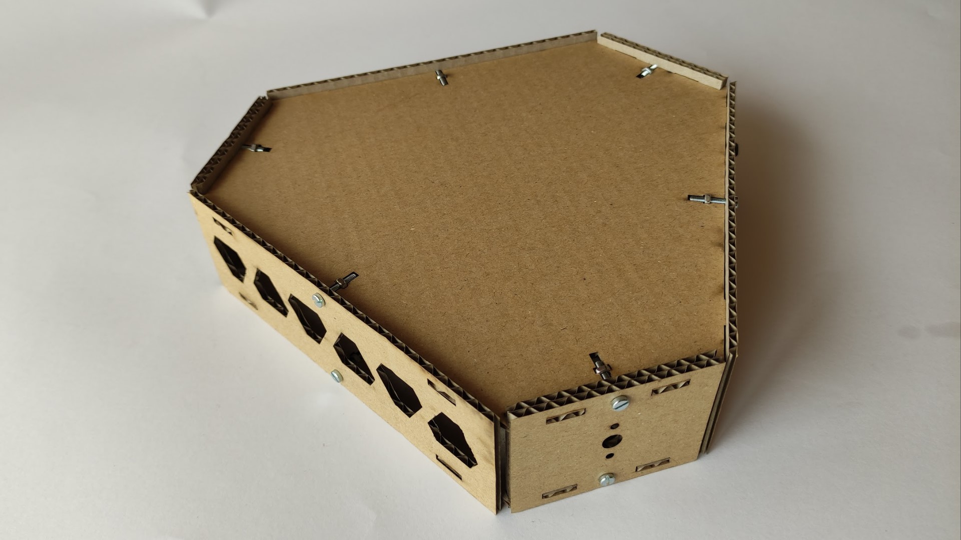
Then my instructor gave me the idea of using a different joint… bolt and nut:
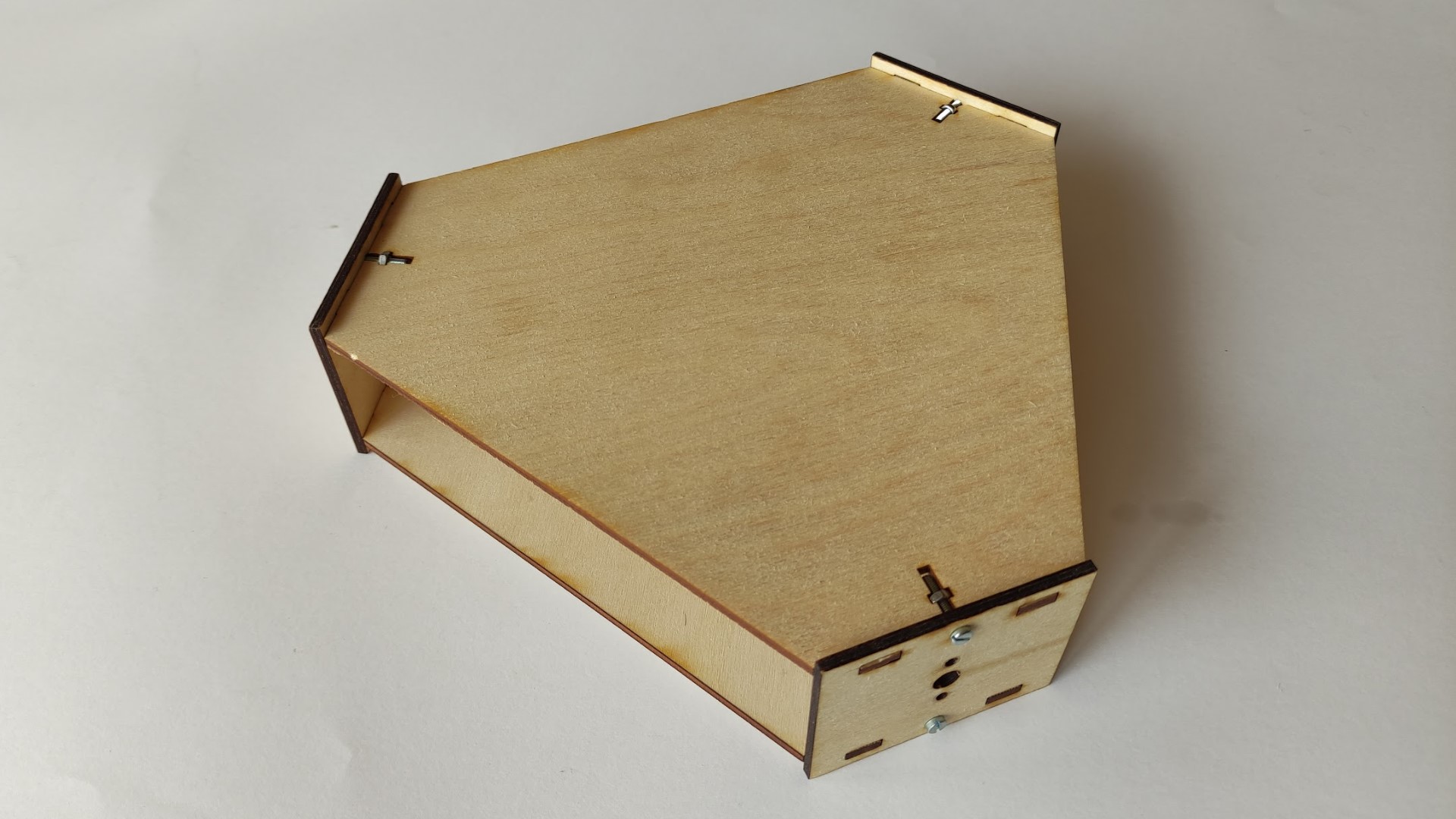
-
Eventually I made double the motor holder pieces so the female tabs are strong enough. I also added more walls so it’s not completely open in some areas, but made this pattern (which is an scale of the shape of the robot to avoid making the radio signal weak):
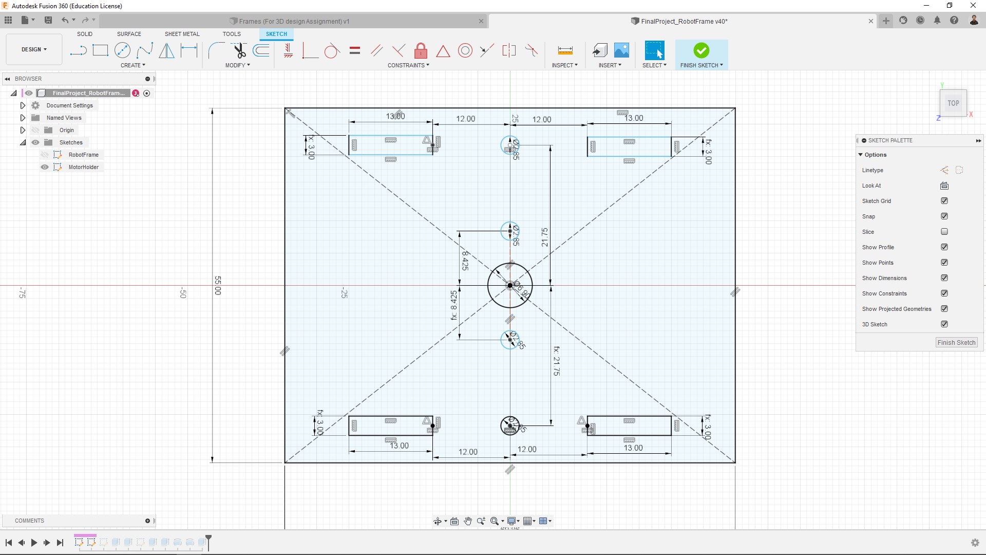
Finally, this is how the final sketches look like:
-
Top and bottom boards:
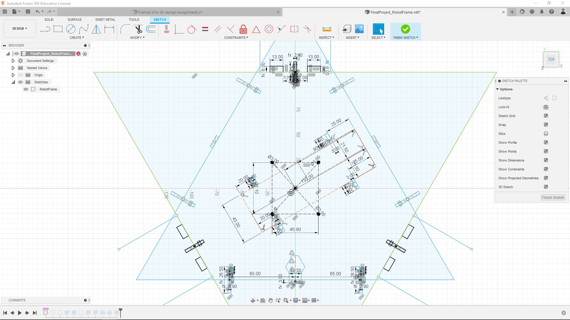
The holes in the middle were intended to be for mounting the board and battery.
-
Motor holders:
-
Walls:
Laser cutting
Further information about a laser cut process in my Computer controlled cutting assignment.
- For setting up the cutting I used RhinoCeros:
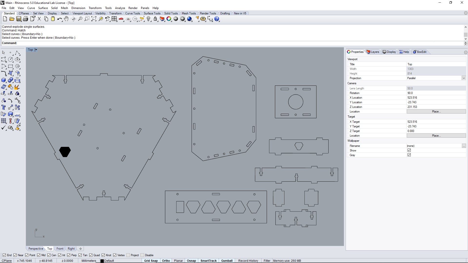
- The laser cutter I used was the Epilog Zing 24 - 30 Watts.
- Parameters used:
* Engrave: Speed: 100%, Power: 25%
* Cut: Speed: 40%, Power: 100%, Freq: 5000Hz
Note: I have cut the pieces together with the Remote control frame.
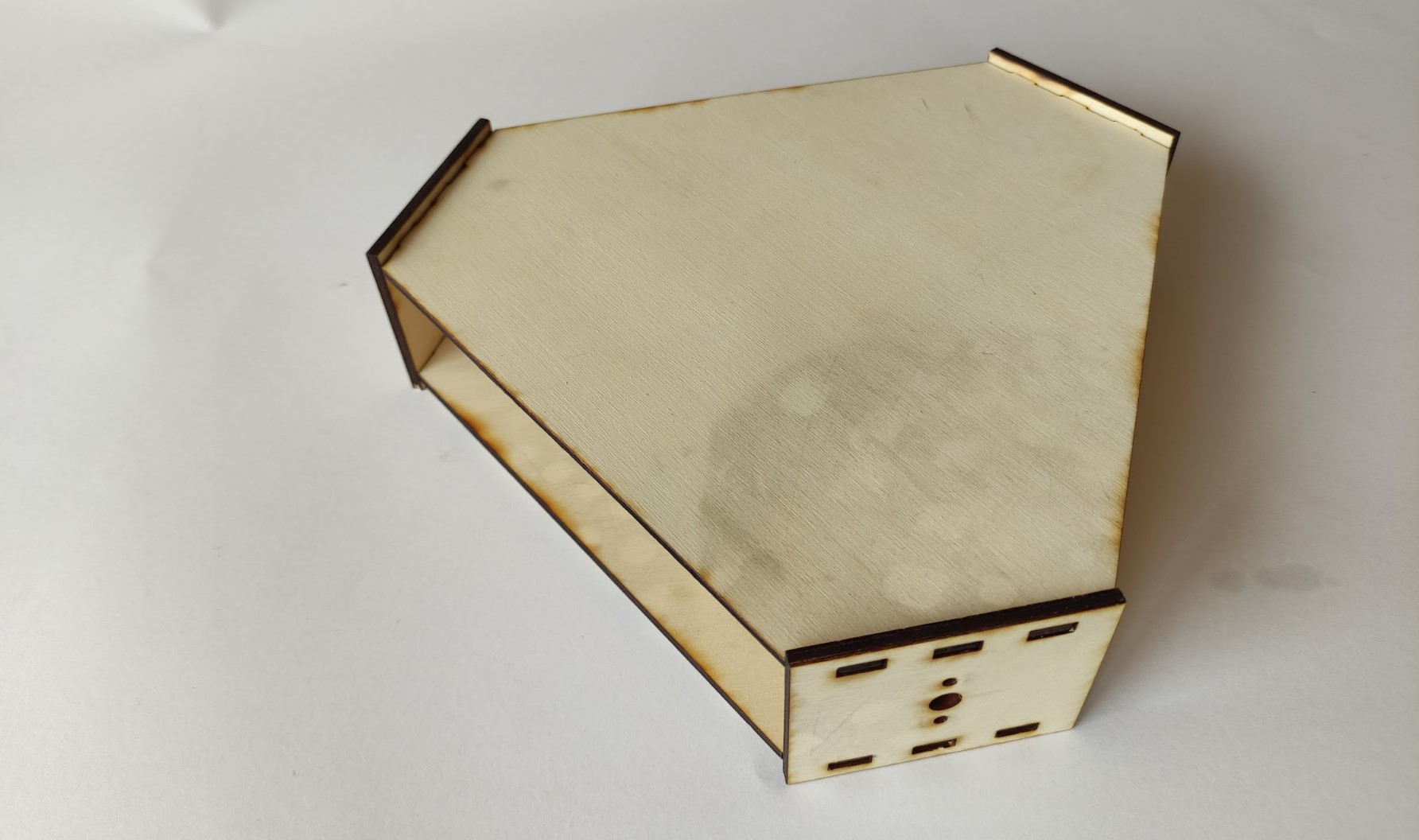
Result:
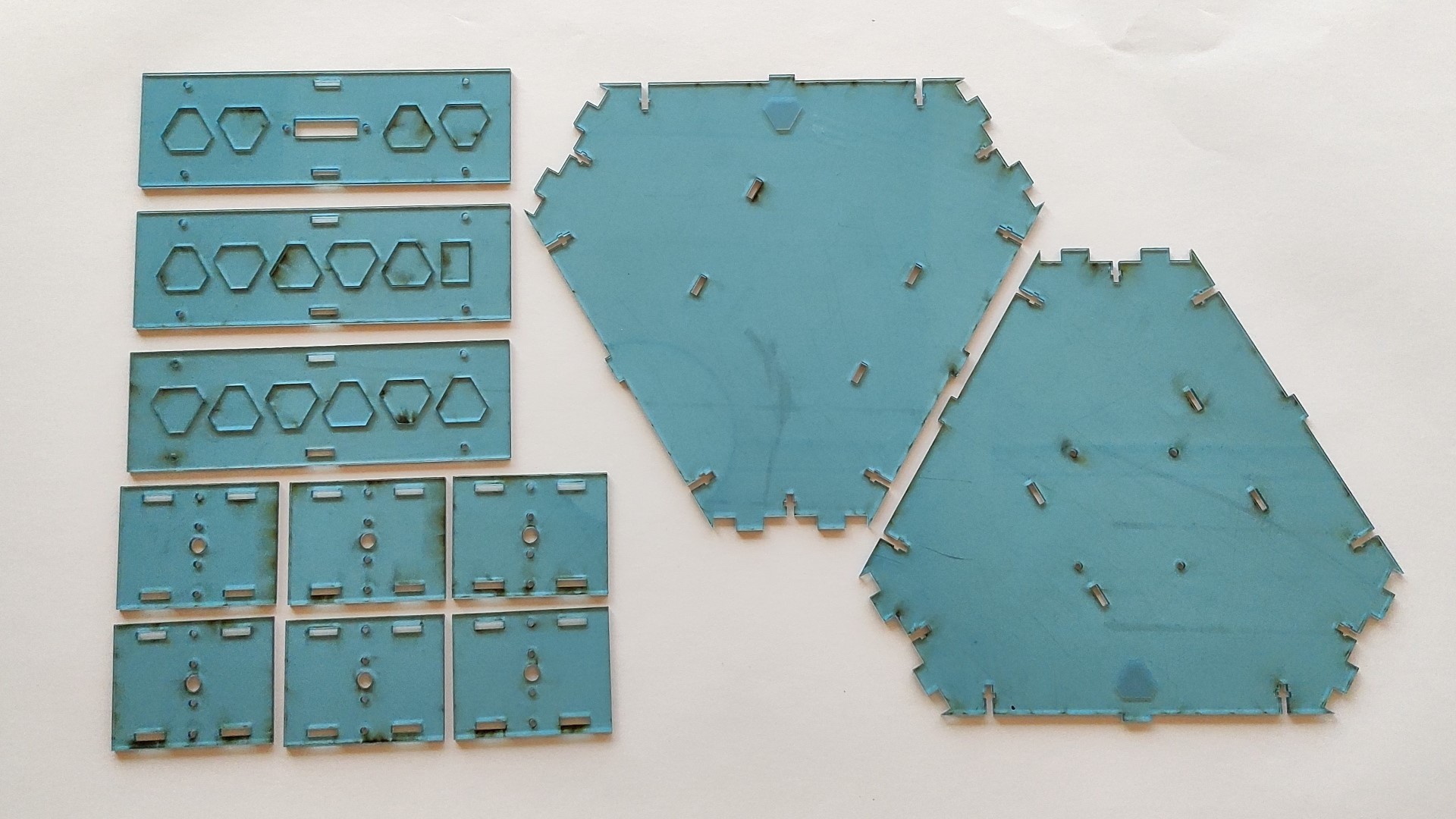
Note: At this point I wasn’t removed the transparent film from the acrylic yet, that’s what looks burned from the laser cutter.
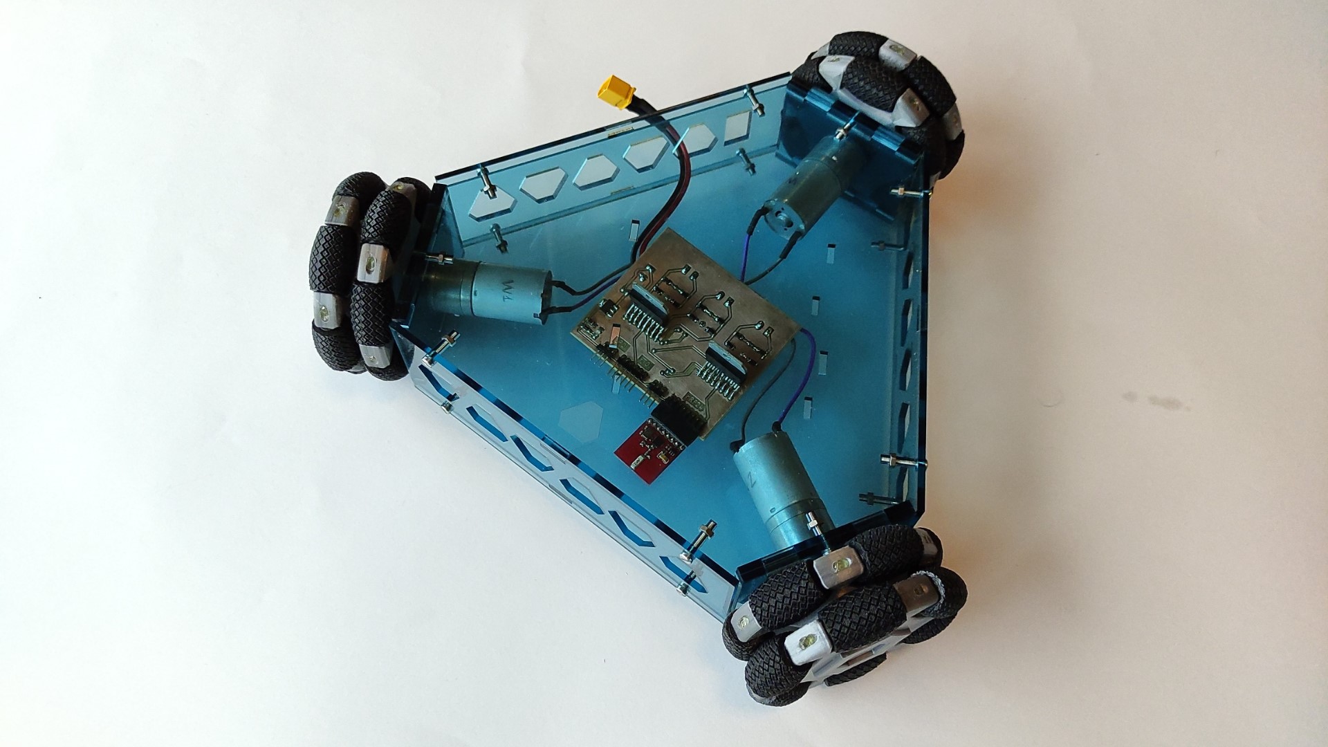
Assembly
At the end, it was just a matter of putting everything together. The frame was assembled using M3 bolts and nuts:
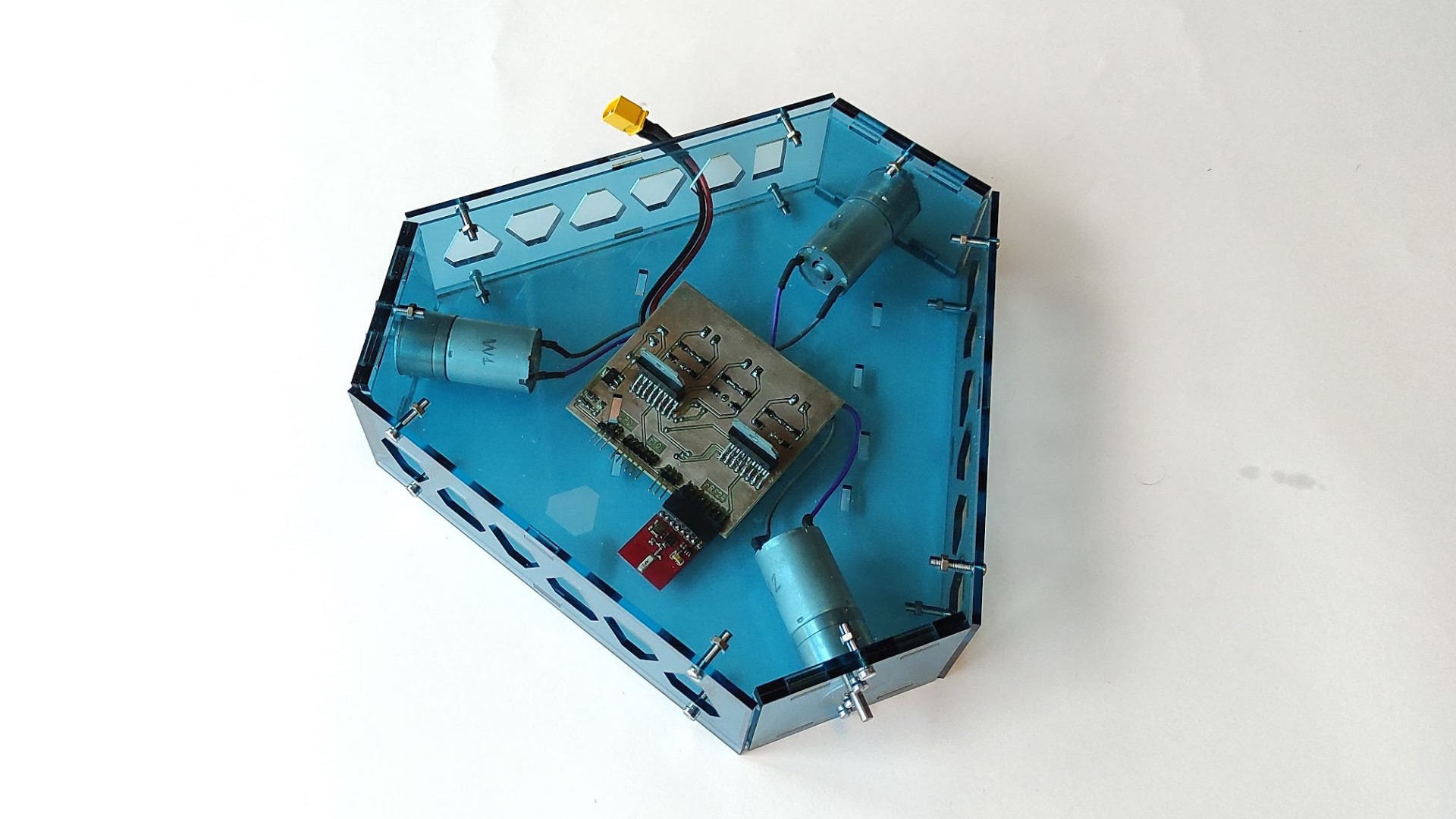
I put the OmniWheels at the end:
Files and references
KiCad project:
-RemoteControlBoardTB6612.zip
-RemoteControlBoardL298.zip
Arduino Code:
RemoteControl.ino
2D Sketches:
- TopBottom.dxf
- MotorHolder.dxf
- Walls.dxf
Datasheets:
- nRF24 Radio transceiver
- ATtiny3216 Microcontroller
- L298 Motor driver
- TB6612FNG Motor driver
- JGA25-370 DC geared motor
- GP2Y0A21YK Infrared Proximity Sensor
Support documentation:
- TB6612FNG Sample Code