13. Output devices | DC-Motor controller
- Measure the power consumption of an output device. Document your work (in a group or individually):
Group assignment page: here.
My individual part:
I have documented it in the Power consumption measurement section.
- Add an output device to a microcontroller board you’ve designed and program it to do something:
Since for my final project, the only output I need are motors, then I worked on that during this assignment, using a 12V DC motor.
First I tried it with a L298N commercial driver board and the microcontroller board that I design during the Electronics design assignment.
Eventually, I designed a board based on the L298N driver chip + an ATtiny1614 Microcontroller chip; this board is made to control only one motor, serving as a first test and experience my for final-project board.
On both tests I used the USB and UPDI adapter boards that I made during the Electronics production assignment.
Power consumption measurement
Since we had to measure the power consumption of an output device for this assignment, besides checking the datasheet of it, I used a power supply and a multimeter for this task; I have done the rest with a 9V battery, since my final project is going to work with batteries.
Voltage measurement (V)
I applied the voltage according to datasheet. (It is a 12V DC-motor)
This is done in parallel to the device:
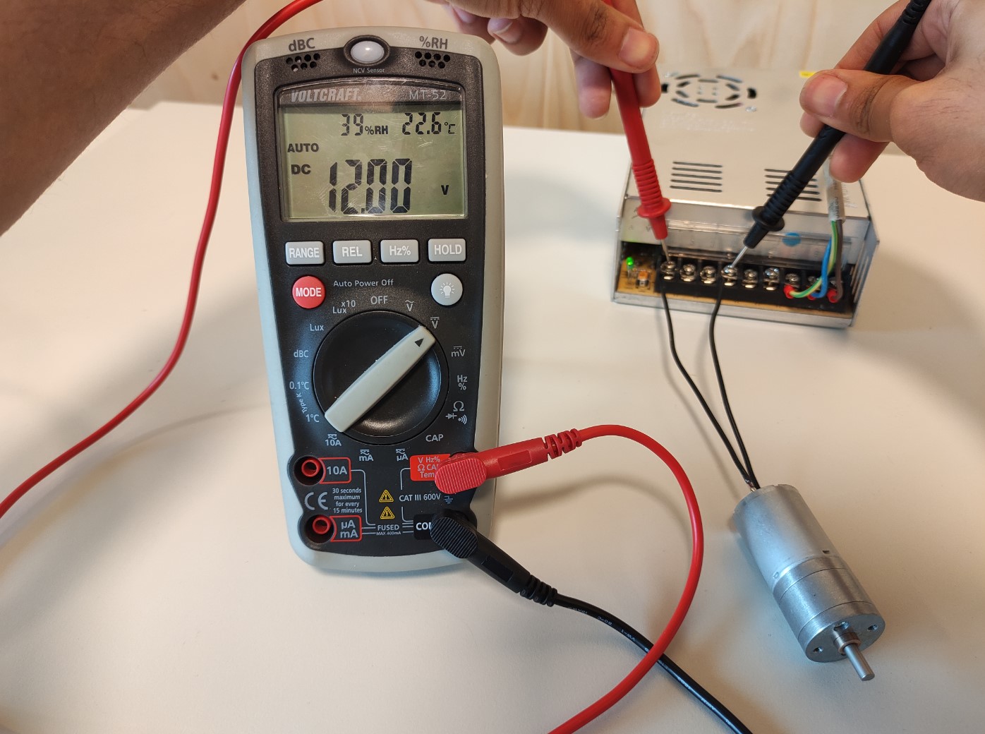
Well, the result are the 12V applied. 🤷🏽♂️
Current measurement (I)
This is done in series to the device:
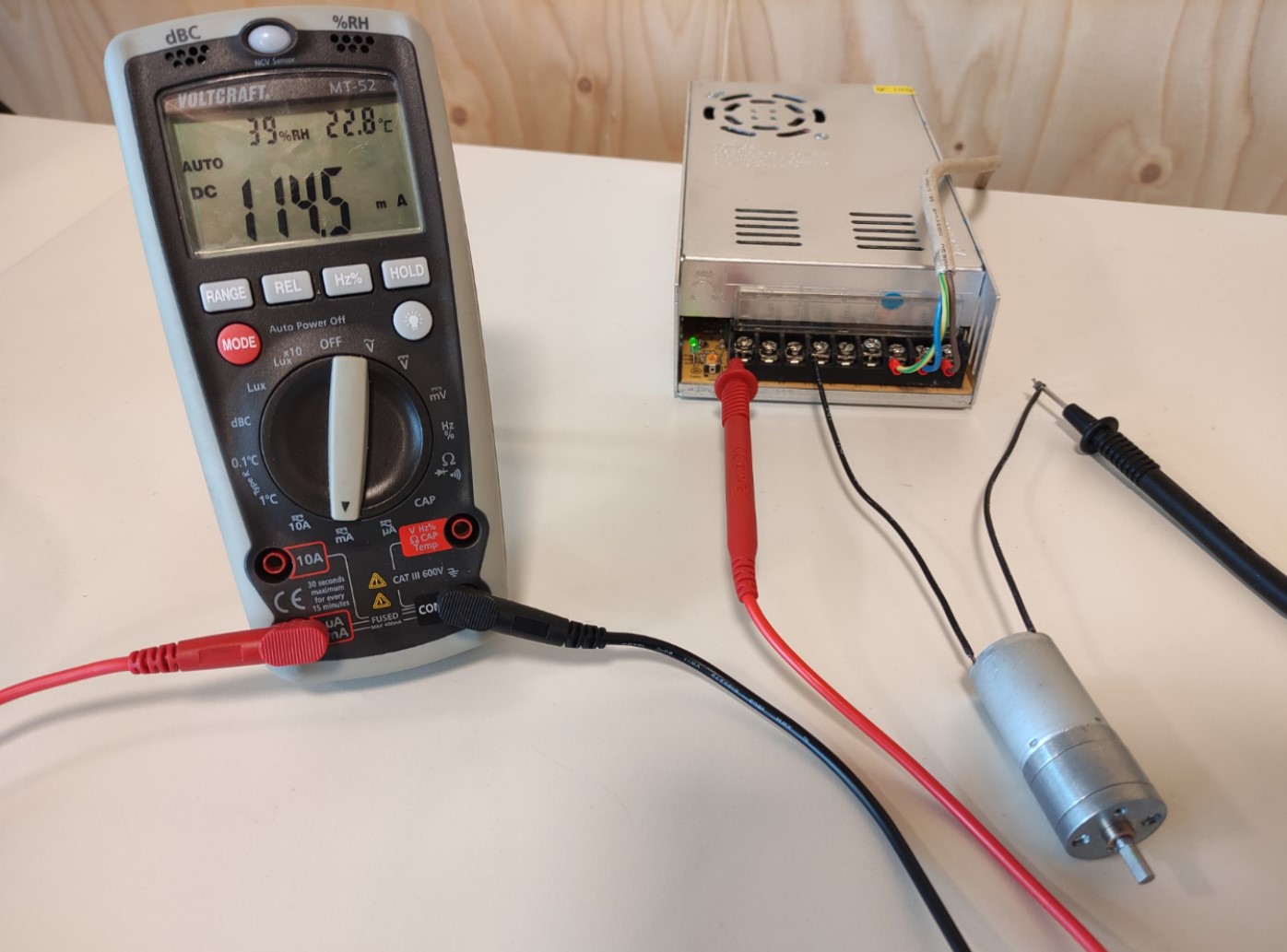
Result: 114.5mA.
Power consumption (P) = V*I = 12V * 114.5mA = 1.37W
Datasheet information
In addition, I compared the values from the datasheet of the motor (a JGA25-370):
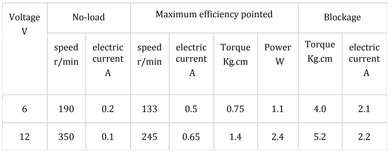
The measured No-load electric current is 14.5mA higher than that from the datasheet.
First test
Circuit
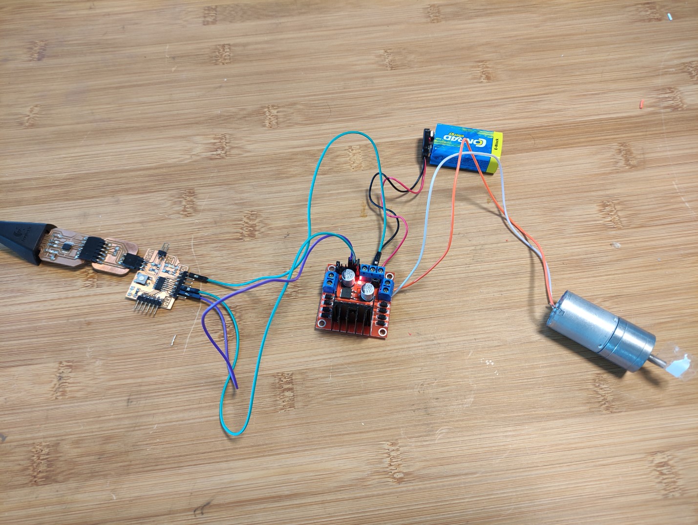
Components
| Qty | Description |
|---|---|
| 1 | MyMiniBoard_X14 |
| 1 | USB FTDI board |
| 1 | FTDI-UPDI adapter board |
| 1 | L298N driver |
| 1 | 12V DC motor |
| 1 | 9V alkaline battery |
| a few | jumper cables |
Physical circuit
Code
1DC_Motor_Test1:
1 2 3 4 5 6 7 8 9 10 11 12 13 14 15 16 17 18 19 20 21 22 23 24 25 26 27 28 29 30 31 32 33 34 35 36 37 38 39 40 | |
Performance
Video1: Test with a commercial L298 driver and my MyMiniBoard_X14
Making my L298N controller board
Now the idea is to make a first testing board that contains a microcontroller (an ATtiny1614 in this case), and a motor driver (a L298N in this case) together.
Since it’s just a testing board I didn’t add any voltage regulator, I take the 5V from my laptop.
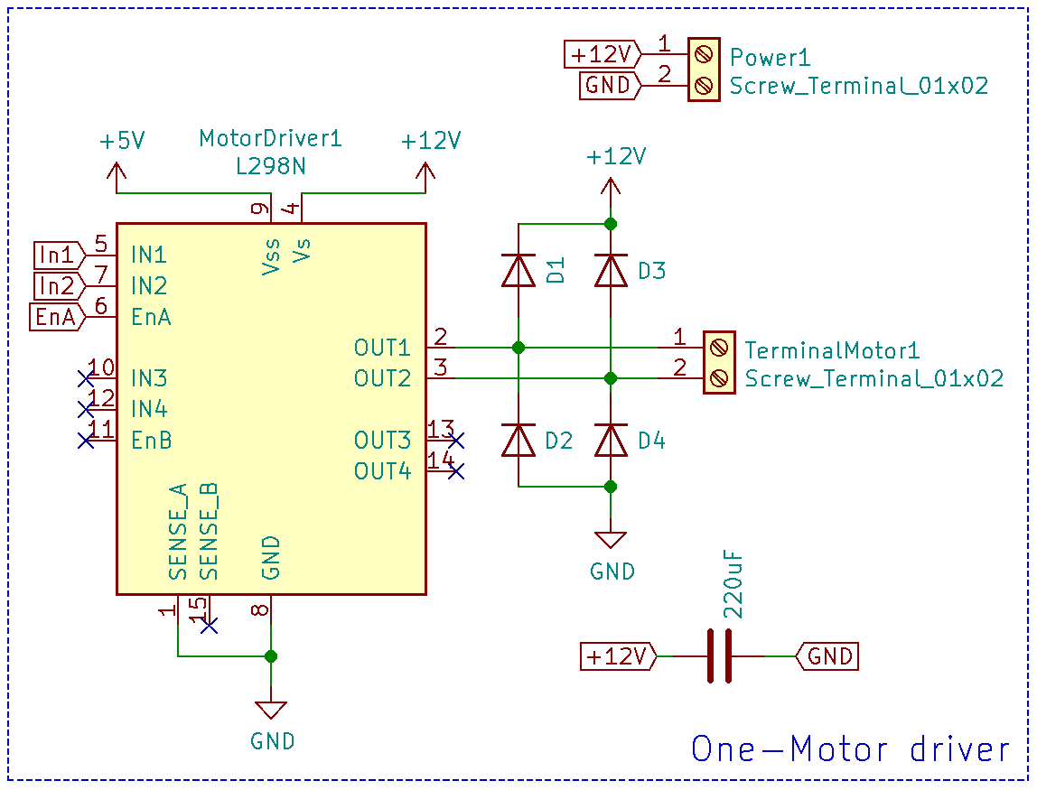
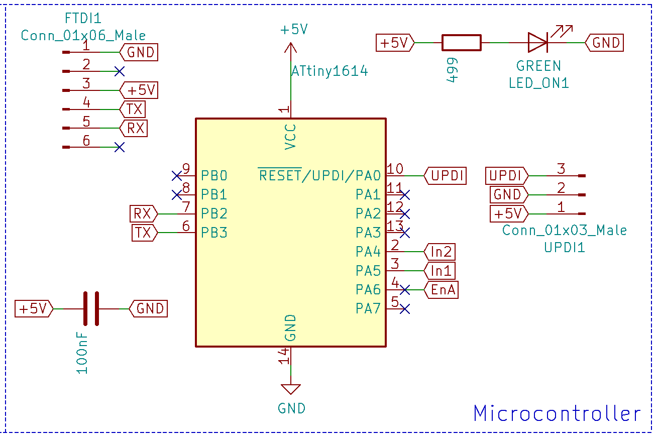
Schematics
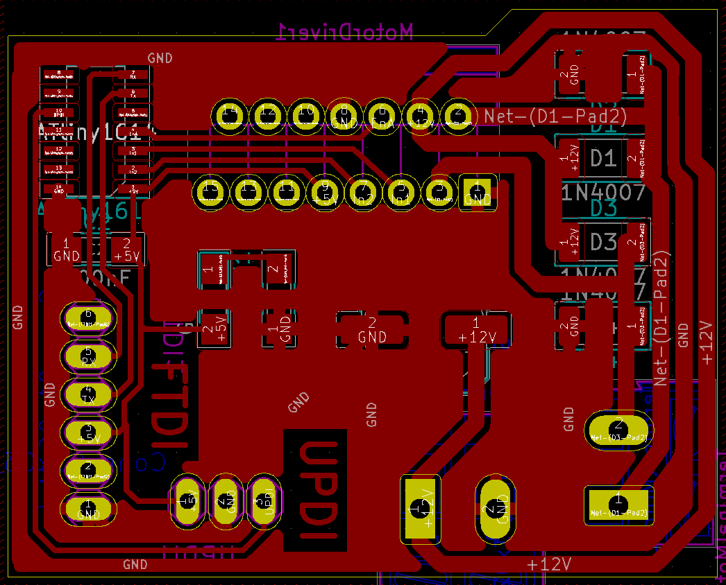
Board layout
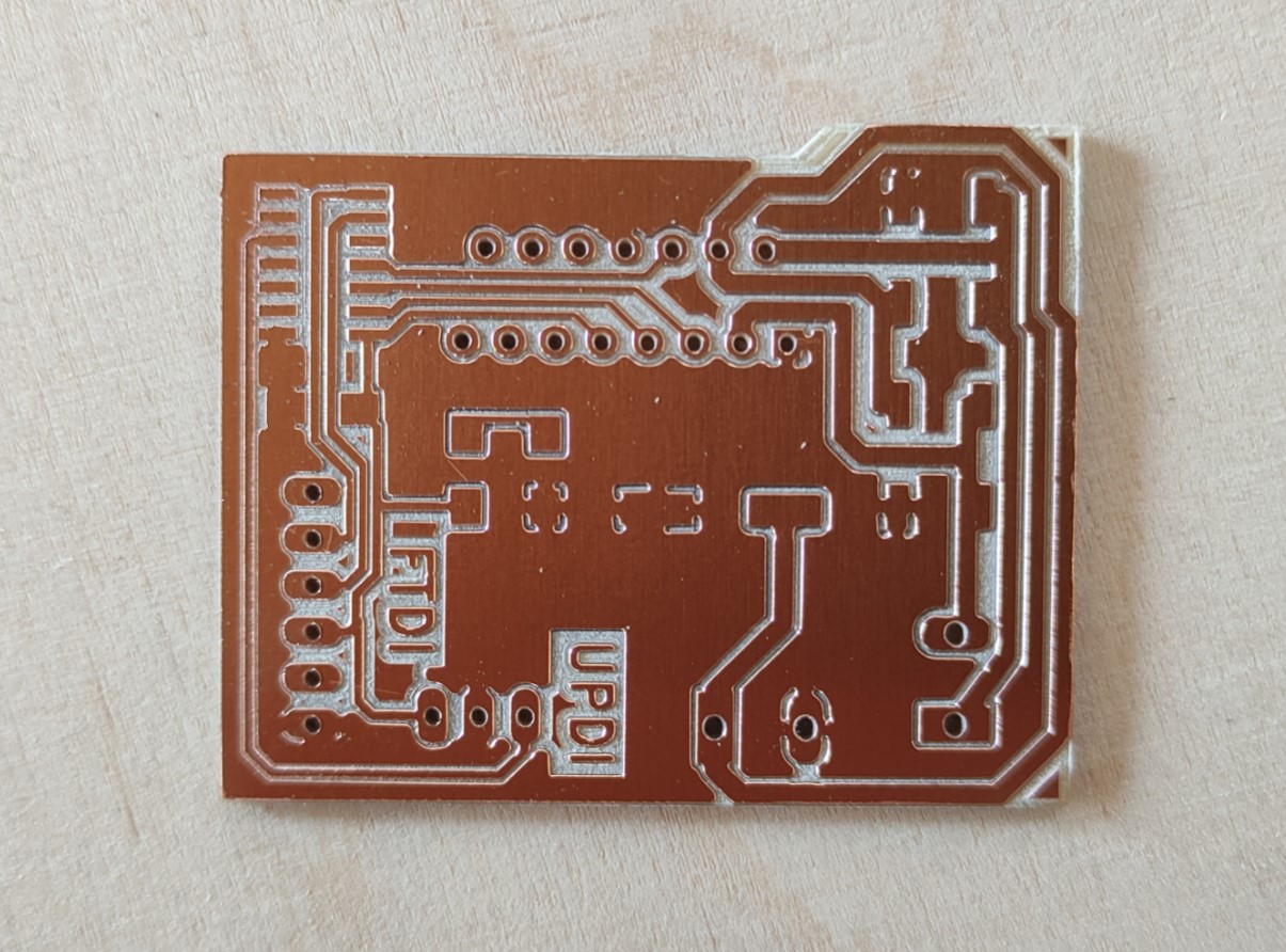
Milling PCB
The milling machine I used was the Roland MonoFab SRM-20.
The tool I used was a V-bit 0.2-0.5mm.
Images:
* Traces:
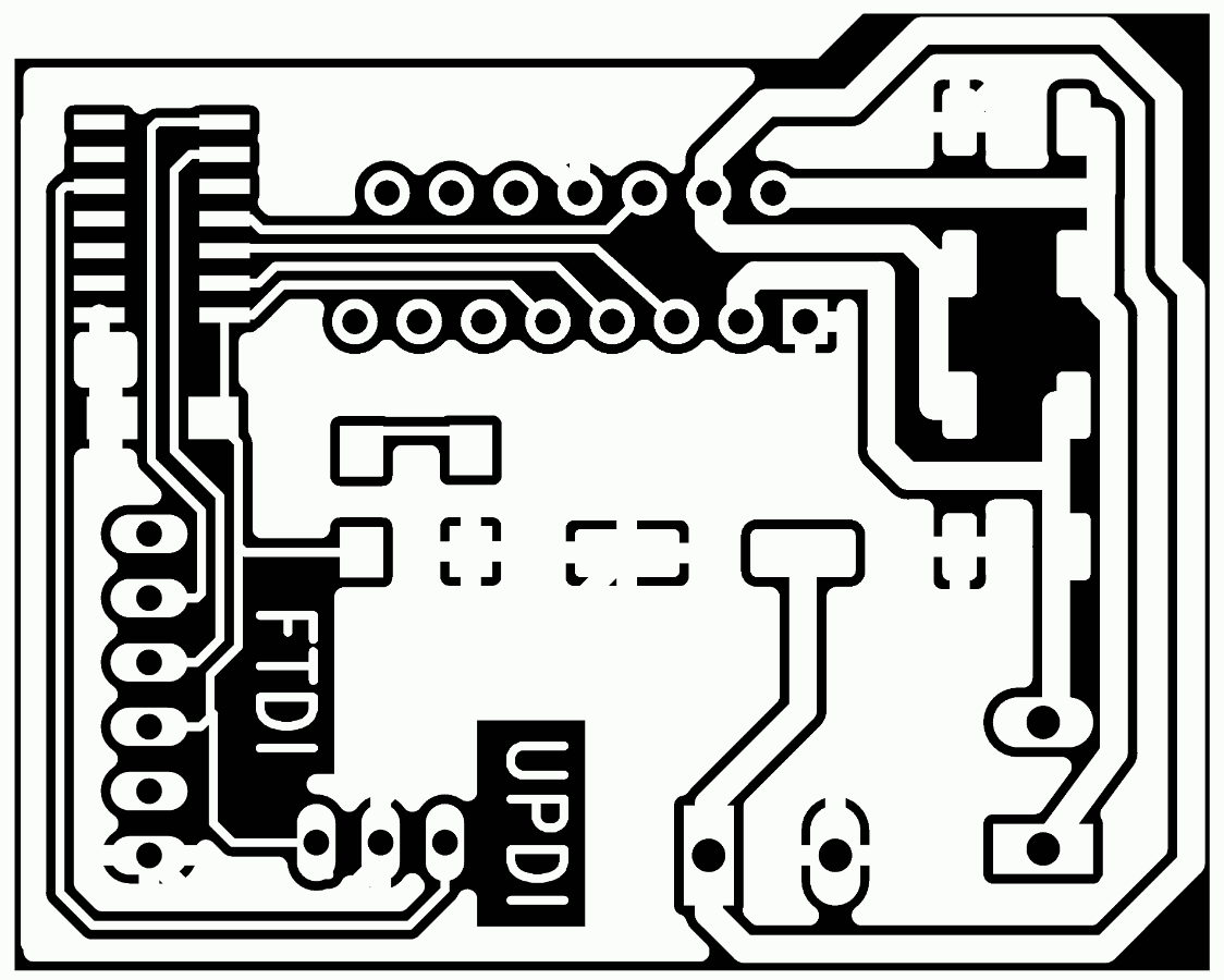
-
Holes:

-
Outlines:

Milled PCB:
Components for the board:
| Qty | Description |
|---|---|
| 1 | L298N driver |
| 1 | ATtiny1614 |
| 4 | 1N4007-SMD diodes |
| 1 | 100nF capacitor |
| 1 | 220uF 35V capacitor |
| 1 | 499Ohms resistor |
| 1 | Yellow LED |
| 9 | Single row right-angle male pin header |
| 2 | Screw terminal 1x2 |
Result
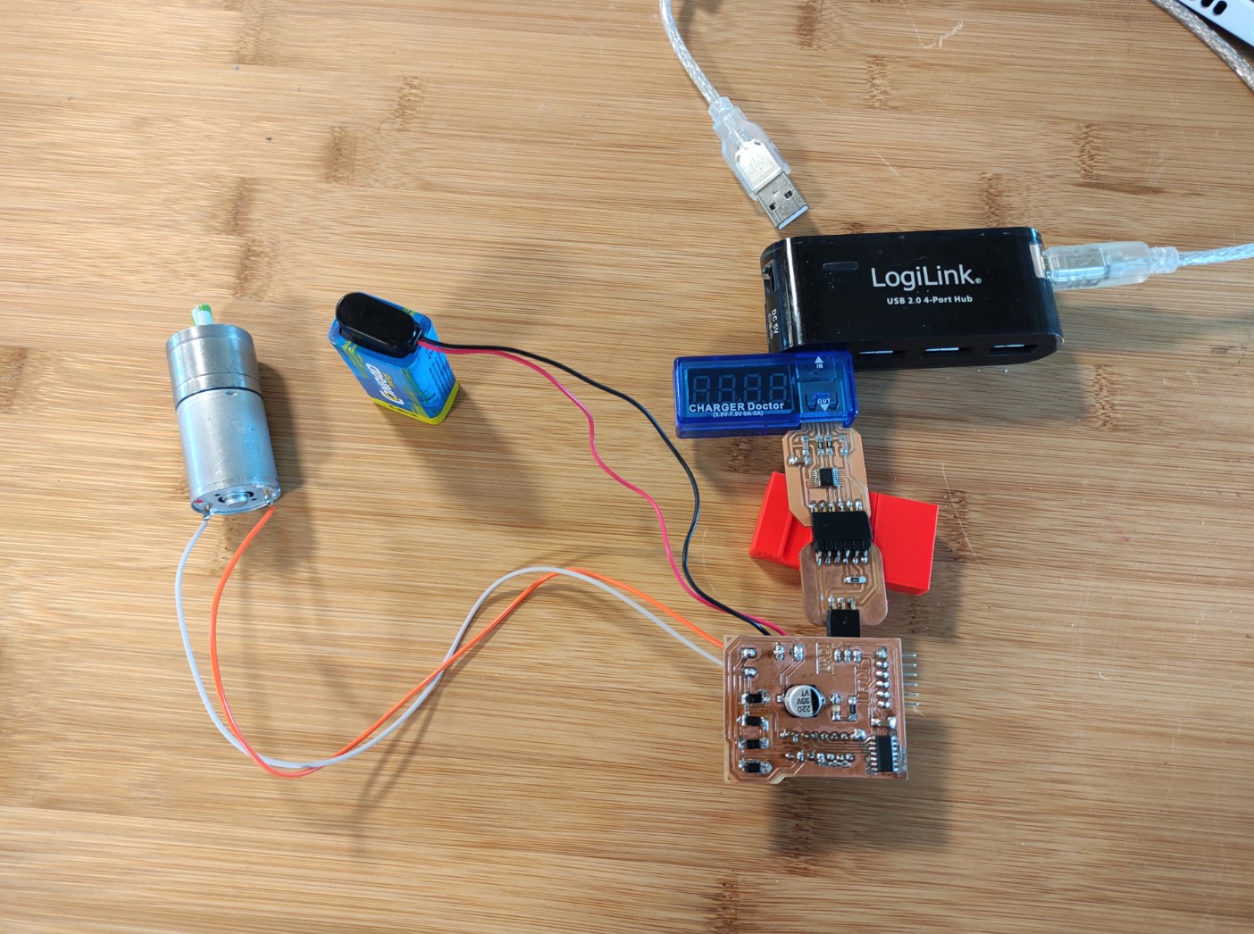
Testing board
Connection
Components
| Qty | Description |
|---|---|
| 1 | USB FTDI board |
| 1 | FTDI-UPDI adapter board |
| 1 | My L298N controller board |
| 1 | 12V DC motor |
| 1 | 9V alkaline battery |
| a few | jumper cables |
I also used a “charger doctor” which is a USB voltmeter and ammeter device so I can find out quickly if something is going wrong even before it could you know… burn! 🔥
Physical circuit
Code
1DC_Motor_Test2:
1 2 3 4 5 6 7 8 9 10 11 12 13 14 15 16 17 18 19 20 21 22 23 24 25 26 27 28 29 30 31 32 33 34 35 36 37 38 39 40 41 42 43 44 45 | |
Performance
Video2: PWM test with L298 driver ATtiny1614 on board
Assignment outlook
For the official board for my final project, I’ll be making just a motor driver (also probably with a chip different than the L298N), one that doesn’t need external diodes 😅. I would like to make a board without microcontroller so I (or someone else) could use it on another projects with their own boards or even with commercial ones; it’s also a good practice using boards for logical and power circuits separated.
I also think bout making microcontroller board in such a way that I don’t need cables to connect it to the driver.
Files and references
- 1DC_Motor_Test.ino
- 1DC_Motor_Test2.ino
- KiCad project: OneMotorDriverL298.zip
Support documentation
- HowToMechatronics. DC motor control
Datasheets
- L298
- JGA25-370 geared motor