Cricut: The cutter of Theseus

If you can't open it, you don't own it!
The purpose of this project during bootcamp was to dissect the Cricut vinyl cutter and hack/reverse engineer it so that we can develop an open source design that can be built in any lab using machines that can be found in any lab.
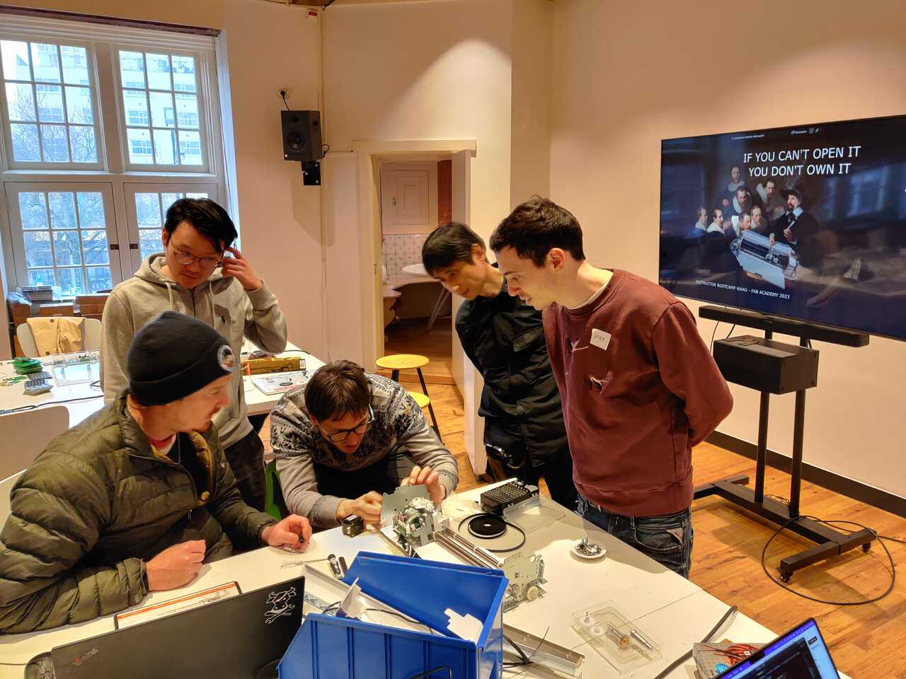
Dissecting the machine
The first step of the process, was to dissect the machine and begin taking it apart so we could understand all of its axes and functionalities. We began by removing the covers and removing any plastic integration so that we could get as close of a look at the mechanisms as possible.
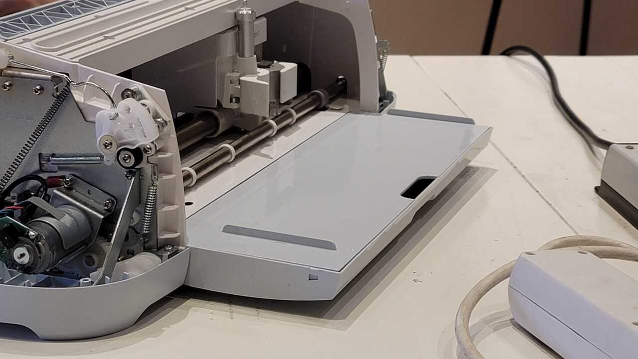
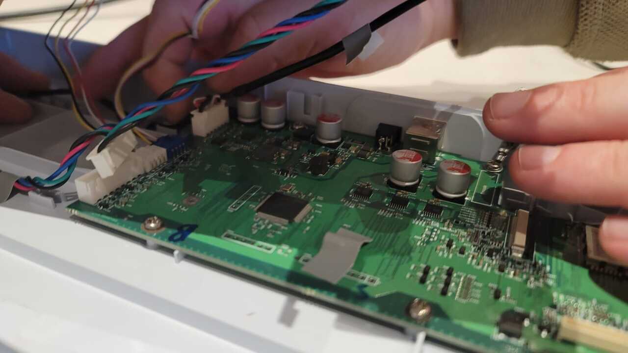
Removing the plastic covers and motherboard
We started by removing the side plastic covers.
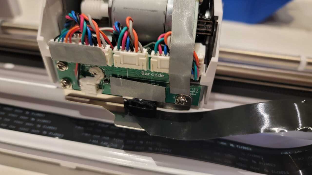
Then we were disconnected all the connectors from the mother board. We were sure to label all of the wires and ports so that we could reverse engineer what the mother board was doing.
Following this we started studying the mechanisms
Studying the mechanisms
Once we had the machine more open, we studied the mechaisms for the x (belt drive), y (roller), z (gear system), and w (gear machanism that rotates the knife).
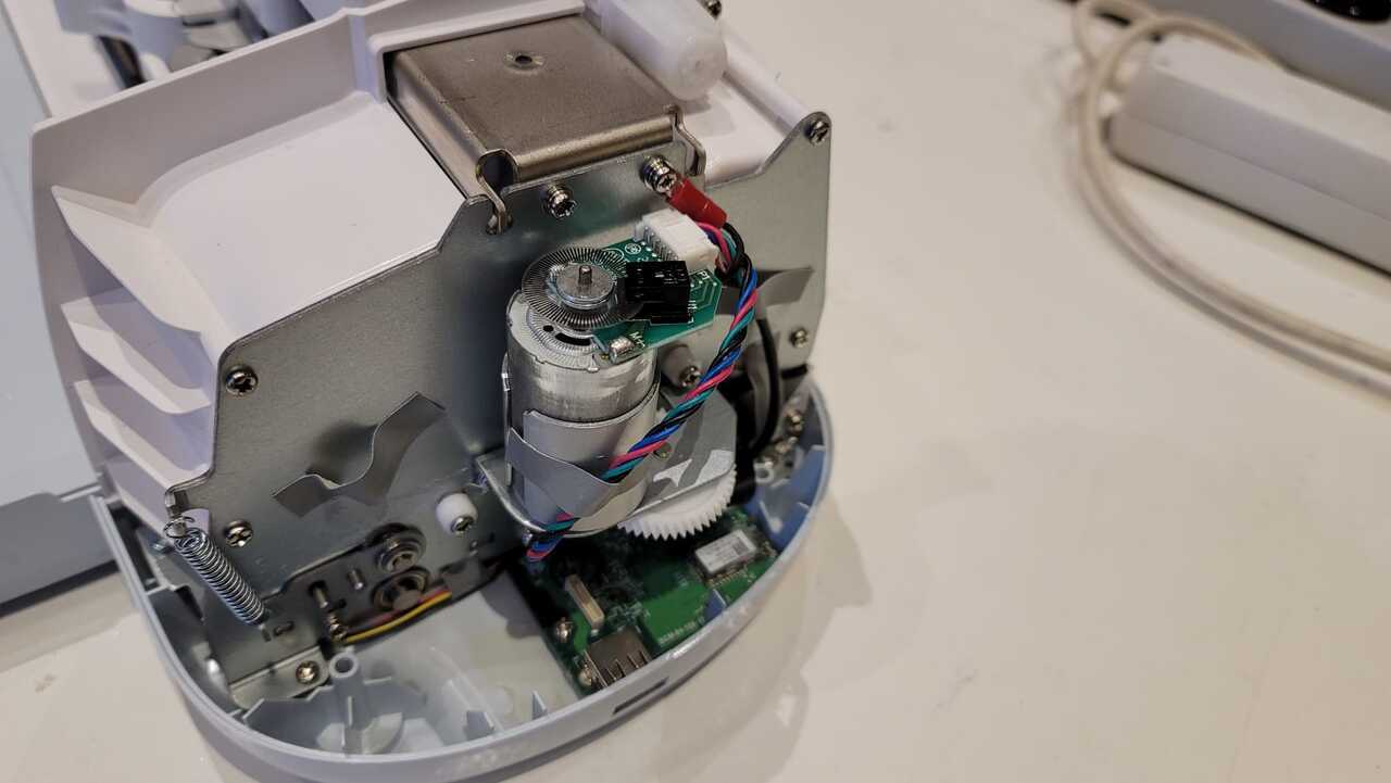
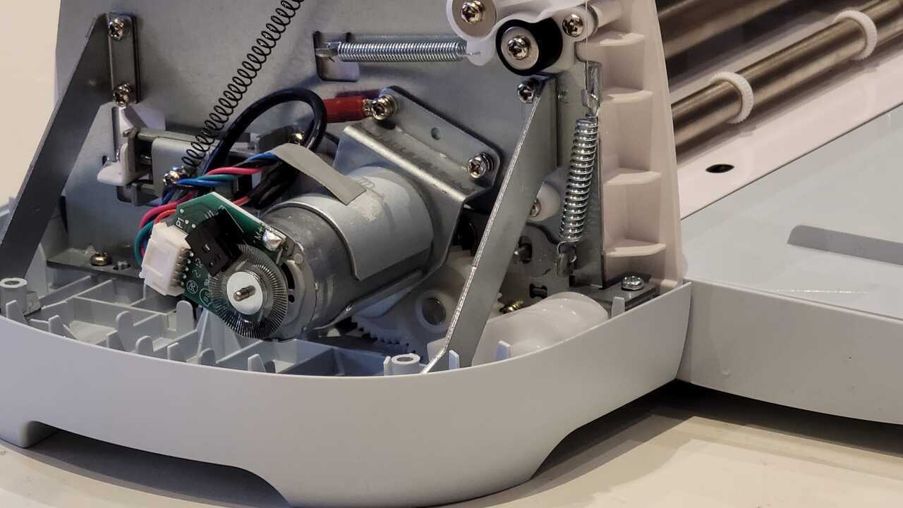
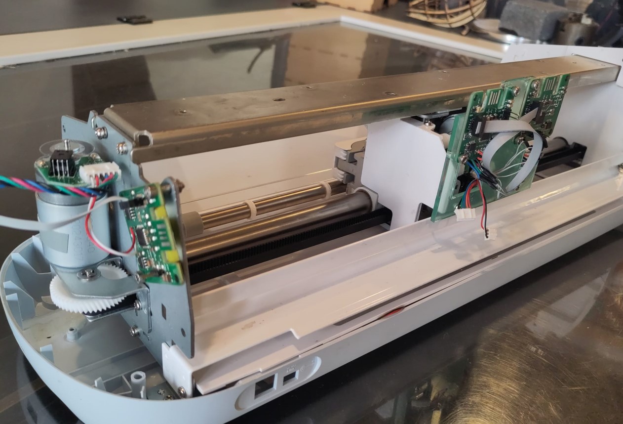
Photo of the x-axis that is belt driven
In this photo you can see the vertical motor with gear set which drives the belt.
In this phot you can see the other side, which has a belt tightener.
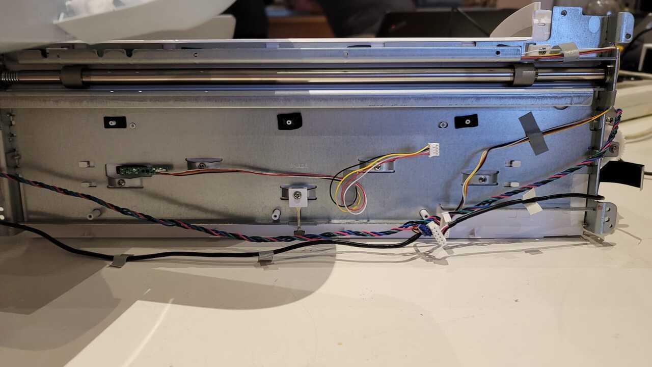
The following photos show the y-axis functionality.
Photo of the y-axis which is a roller driven by a gear set
Photos of the x and w axes
It was not posible to get a good photo of the z-axis, but it was driven using a gear system.
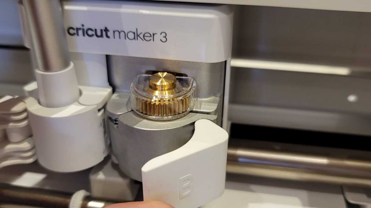
This is a phot of the worm gear that drives the w-axis which drives the knife.
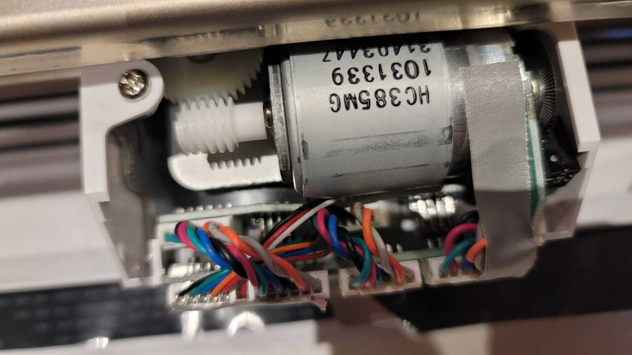
and hear is the front of the w-axis mechanism which drives and turns the knife.

Studying the electronics
The next step was to study the electronics, and determine how each of the mechanisms was controlled electronically. After close inspection, we noticed the following controls.
Control of the axes
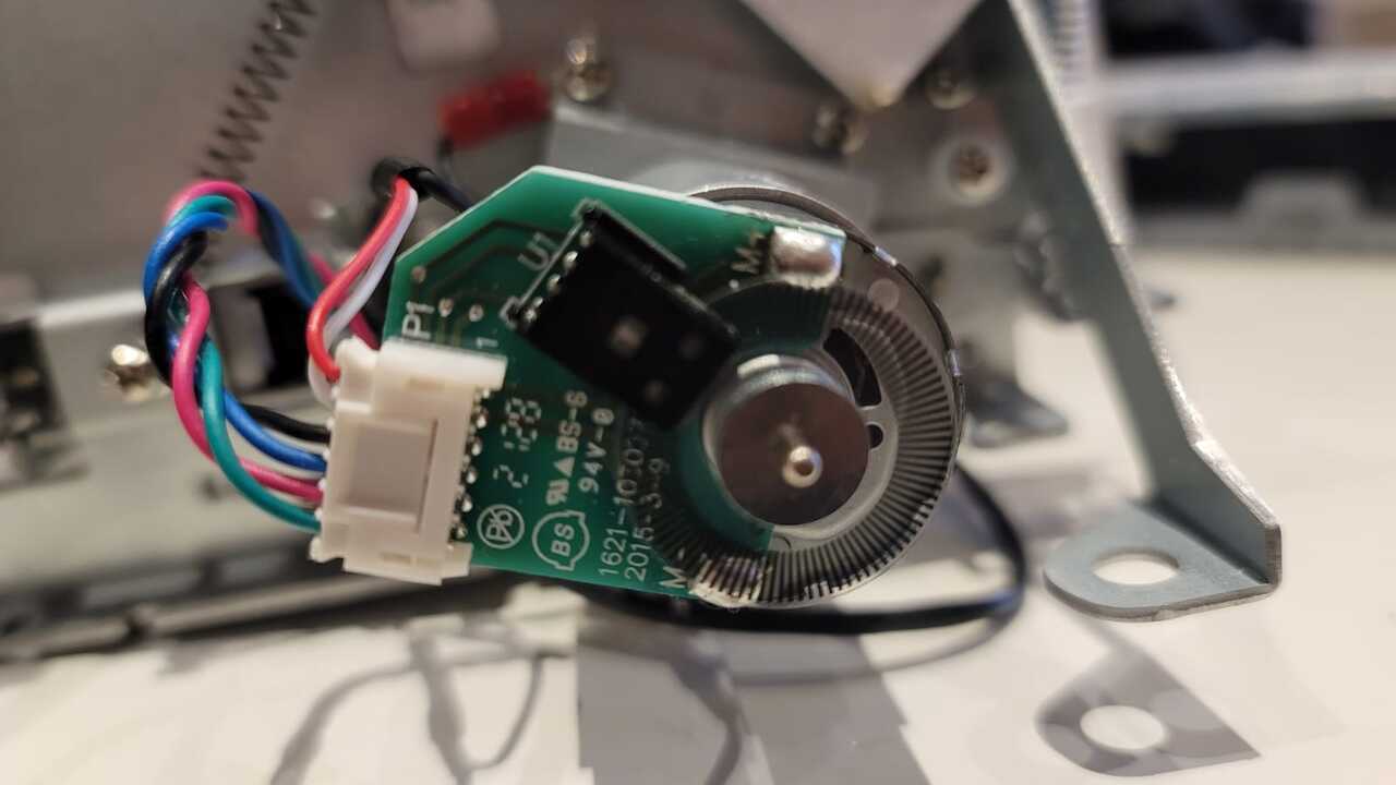
All of he axes were controlled using a dc moder with encoder, which essentially works in combination to provide the same effect as a stepper motor. The encoder works using an optical sensor with a circular disk that has lines. The optical sensor is then able to tell the position of the motor by counting the lines that pass accross the optical sensor.
Below is a photo of encoder and optical sensor
next we will discuss the control of the endstops.
Control of the end stops and zero mechanism
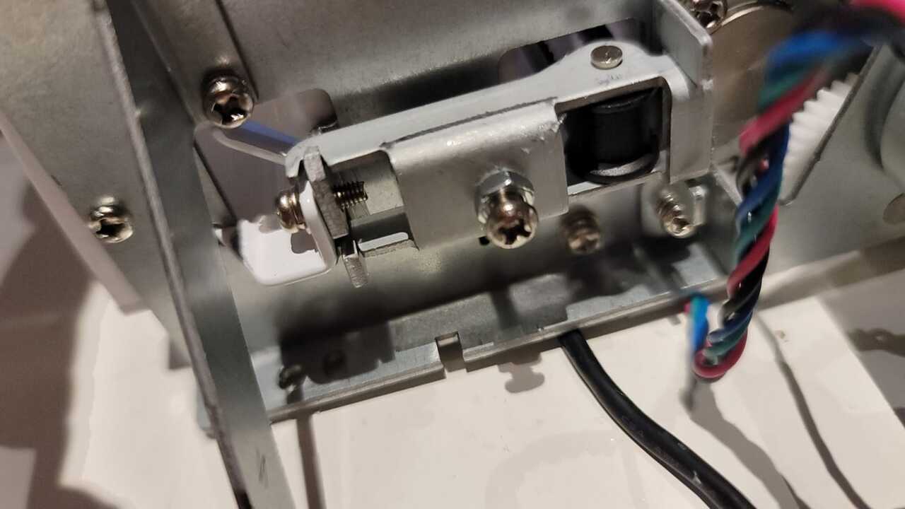
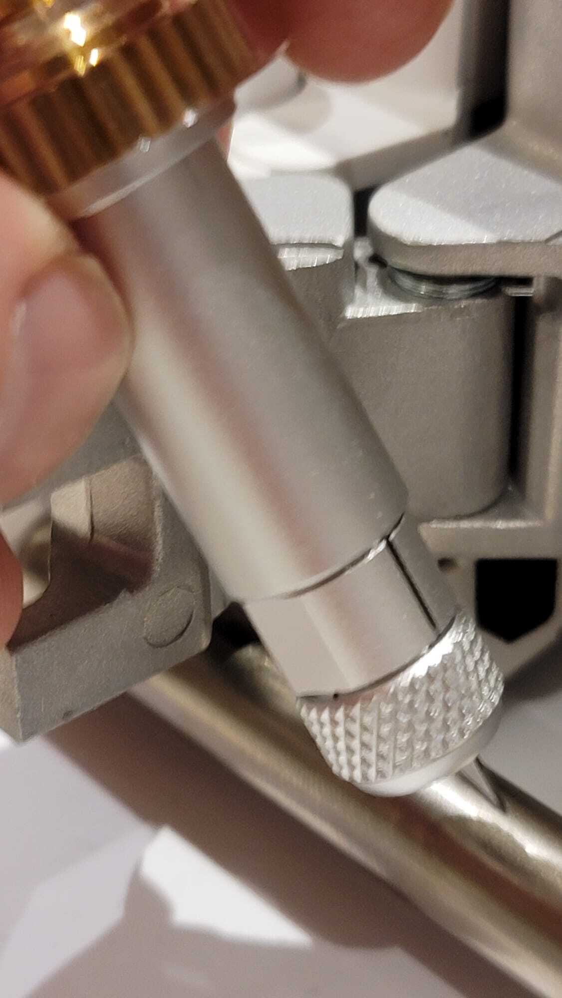
The end stops and zero mechanims were also optically controlled. The zero for the w-axis (rotating knife), used an optical reflector that would send a signal when there was a reflection. The two sides of the knife had flat parts on them and the orientation when homing was determined because the size of the flat end was different depending on the side. In the photos below you can see the optical control for the knife.
zero mechanism for the knife holder
In this photo you can see the flat portion on the knife holder.
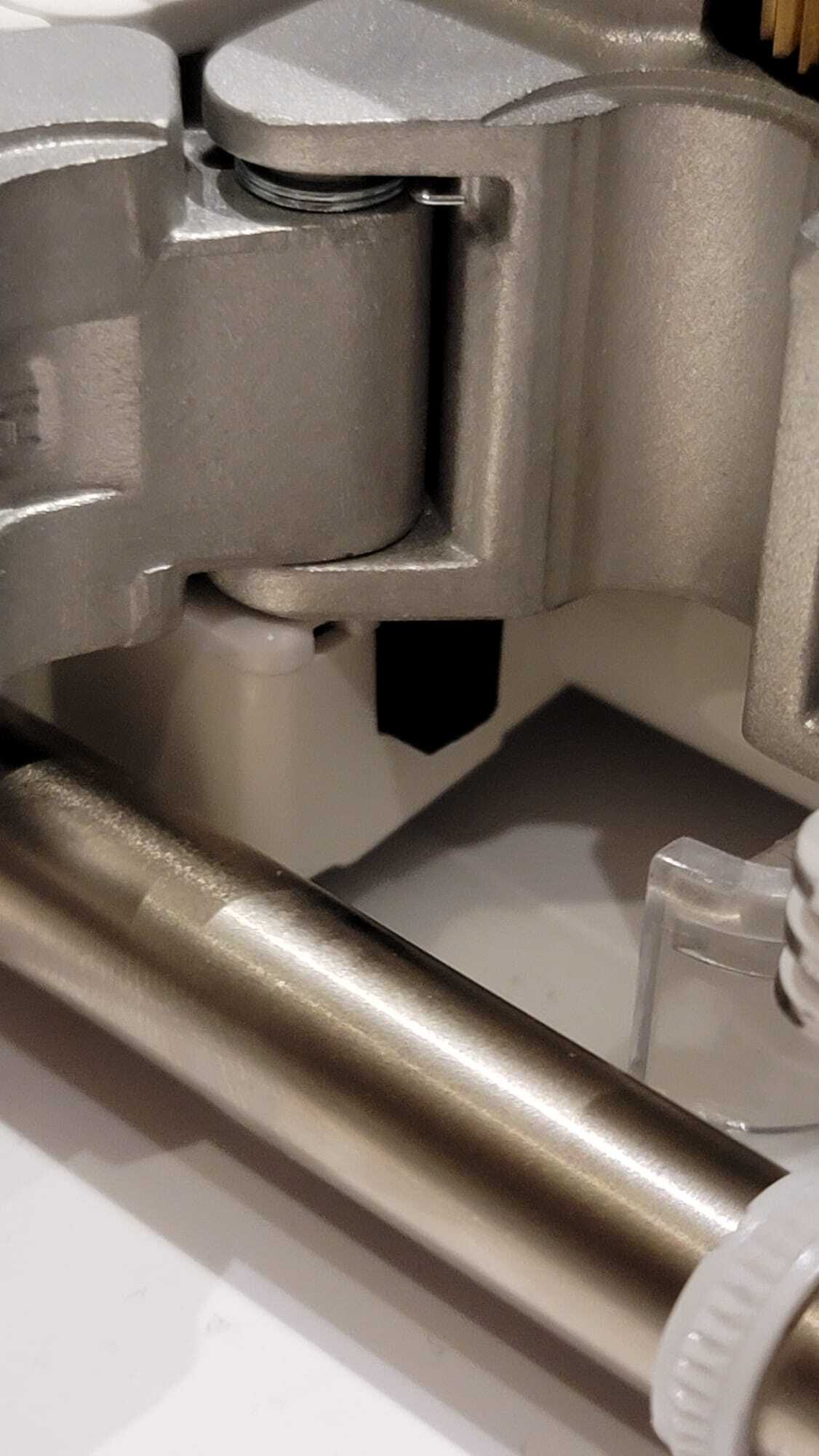
In this photo you can more closely see the optical reflector at the bottom of the carriage. It appears as a black square.
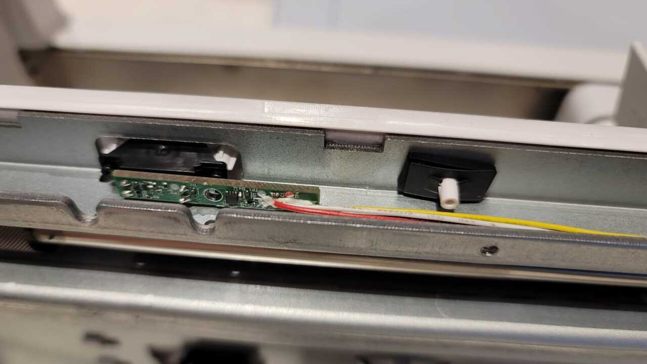
zero mechanism for end stops
In this photo you can see where the endstops are position. on the bottom you see the infrared optical sensor that is used.
Once we had a proper understanding of how the machine works, the next step was to determine how to replicate it.
Custom electronics
In the spirit of testing the latest tech from CBA, we decided to use modular things boards for each functionality in the machine.
In the most basic scenario, that's 4 motor modules. The optical endstops can be connected to those boards, so this could be enough to drive the whole machine.
The DC motor + optical encoder posed a challenge, as we don't have a bespoke board for that purpose. We managed to repurpose a stepper H-bridge board. The idea is to only use one of the two H-bridges to drive the DC motor, and use general GPIO for decoding the optical encoder.
Quentin wrote a basic firmware that uses pins PA30 and PA31 (SWCLK and SWDIO, respectively) as two interrupt input pins. As these pins are normally used for programming, they were available on the SWD connector and we simply made a custom cable for connecting to the Cricut's motors (you can see examples of that on the boards on the right):
The firmware can be found here.
The remaining challenge is tuning the PID adequately.
It also seems the 5V from the USB cable is barely enough to get enough torque on the motor. The Cricut most definitely runs the motors at 12V or even 24V, but with proper PID it might still be OK.