Week 6 - Embedded programming
This week’s assignment included the following tasks:
- Browse through the datasheet for your microcontroller
- Compare the performance and development workflows for other architectures
We compared: * ATtiny85 * ATSAMD11C * ESP32 * RP2040
TABLE COMPARISION
| SPECS | ATtiny85 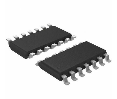 |
ATSAMD11C  |
ESP32 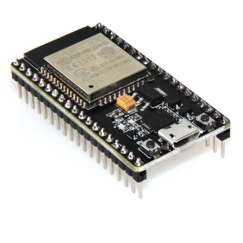 |
RP2040 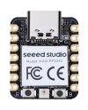 |
|---|---|---|---|---|
| PROCESSOR | AVR-RISC, up to 20 MHz | ARM Cortex-M0+ CPU, up to 48MHz | CPU: 32-bit Xtensa LX6 dual-core (or single-core) microprocessor, operating at 160 or 240 MHz and yielding up to 600 DMIPS and the Ultra Low Power (ULP) co-processor | Dual Cortex M0+ processor cores, up to 133 MHz |
| PINS | 14 | 14 | 9 pins for contact sensors and 16 PWM. | 26 |
| I/O PINS | 12 | 12 | 25 digital inputs/outputs | 15 (11 Digital, 4 Analog) |
| OPERATING VOLTAGE | 2.7 – 5.5V | 1.62V – 3.63V | 2.2 to 3.6V | 3.3V - 5V |
| FLASH | 8KB | 16KB | 4MB | 2MB |
| SRAM | 0,5KB | 4KB | 400KB SRAM | 264KB |
| TIME COUNTER (TC) | 8-bit | 2 | 64-bit generic timers based on 16-bit pre-scalers and 64-bit up / down counters | 21 bit |
| TIME COUNTER FOR CONTROL | 2 | 1 | 2 | 1 |
| USB INTERFACE | 0 | 1 | 1 | 1 (Type C) |
- ATtiny85: Best for simple, low-power applications like LED drivers or sensor interfaces, due to its simplicity and low resource requirements.
- ATSAMD11C: Suitable for intermediate projects needing higher processing power and USB connectivity, with a balance between capability and ease of use.
- ESP32: Ideal for advanced IoT projects with its high processing power, extensive memory, and built-in Wi-Fi/Bluetooth, offering wide development platform support.
- RP2040: Versatile for projects requiring custom I/O operations and supports a wide range of programming environments, lacking built-in wireless connectivity.
PERFORMANCE ANNALYSIS
ATtiny85
- Pinout
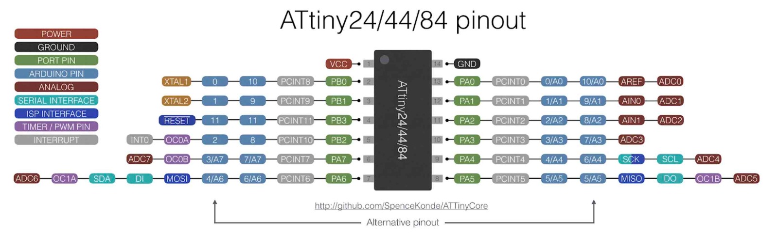
- low-power microcontroller from the AVR family
- designed for simple applications with modest computational needs
- it has 8 KB of flash memory, 512 bytes of EEPROM, and 512 bytes of SRAM
- operates at up to 20 MHz
- can be programmed with Arduino or USBtinyISP
- development environment: generally AVR-GCC and AVR Libc
- suitable for basic applications like simple sensor interfaces, LED drivers, etc.
- Datasheet
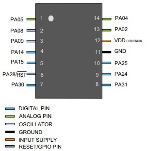
ATSAMD11C
-
Pinout
-
32-bit ARM Cortex-M0+ microcontroller
- higher performance than the ATtiny85
- designed for slightly more complex tasks
- can operate up to 48 MHz
- typically comes with 16 KB of flash memory and 4 KB of SRAM
- usually programmed using the Atmel Studio or Arduino IDE
- it supports sophisticated development tools and debugging options
- appropriate for intermediate projects that require higher processing capabilities and USB functionality
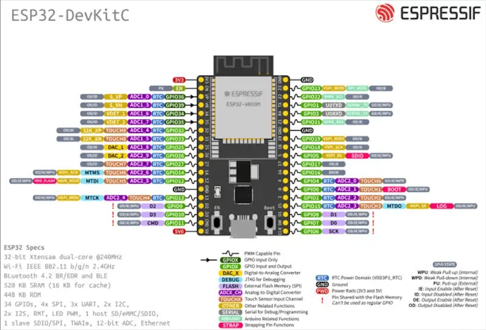
ESP32
-
Pinout
-
high-performance microcontroller with integrated Wi-Fi and Bluetooth
- dual-core processor that can run up to 240 MHz
- up to 520 KB of SRAM and higher flash memory options
- ideal for IoT applications
- supports various development platforms, including the Arduino IDE, MicroPython, Espressif IDF, etc
- it offers features like networking, OTA updates, and deep sleep modes
- due to these features, the development environment is more complex
RP2040
- Pinout
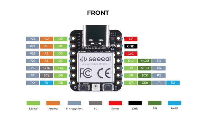
- dual-core ARM Cortex-M0+ microcontroller
- operates at up to 133 MHz
- 264 KB of SRAM and supports external flash memory
- known for its programmable I/O feature
- can be programmed using C/C++ SDK, MicroPython, or CircuitPython
- popular for its ease of use and set of libraries available
DEVELOPMENT WORKFLOW ANNALYSIS - SETTING UP A “HELLO WORLD”/BLINKING PROGRAM
We tested the workflow of RP2040 (included in the Quentorres boards we made Electronics Production week) and the ESP32 (included in the Barduino board from FABLAB BCN):
Testing RP2040 with Arduino IDE
- Download and install the Arduino IDE from the Arduino website
- Add RP2040 Boards to Arduino IDE:
- Open the Arduino IDE
- Go to File > Preferences
- In the “Additional Boards Manager URLs” field, add the URL for the Raspberry Pi Pico/RP2040 boards: https://github.com/earlephilhower/arduino-pico/releases/download/global/package_rp2040_index.json
- Go to Tools > Board > Boards Manager, search for “RP2040”, and install the “Raspberry Pi Pico/RP2040” by Earle Philhower
- Connect the board with the RP2040 to the computer with a micro-USB cable
- Select the board and port:
- Tools > Board and select “Raspberry Pi Pico”
- Tools > Port for the COM port the USB is connected to
- Write and verify code
- Go to File > Examples > 01.Basics > Blink
- Opend the file
// the setup function runs once when you press reset or power the board
void setup() {
  // initialize digital pin LED_BUILTIN as an output.
  pinMode(LED_BUILTIN, OUTPUT);
}

// the loop function runs over and over again forever
void loop() {
  digitalWrite(LED_BUILTIN, HIGH);  // turn the LED on (HIGH is the voltage level)
  delay(1000);                      // wait for a second
  digitalWrite(LED_BUILTIN, LOW);   // turn the LED off by making the voltage LOW
  delay(1000);                      // wait for a second
}
- Looking for the pinout to change the file
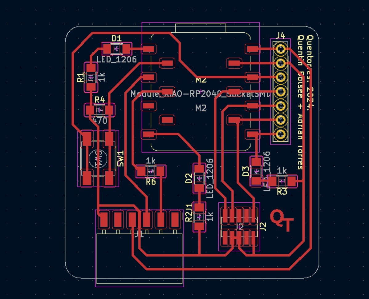
- Changing pinMode and adding two other LED
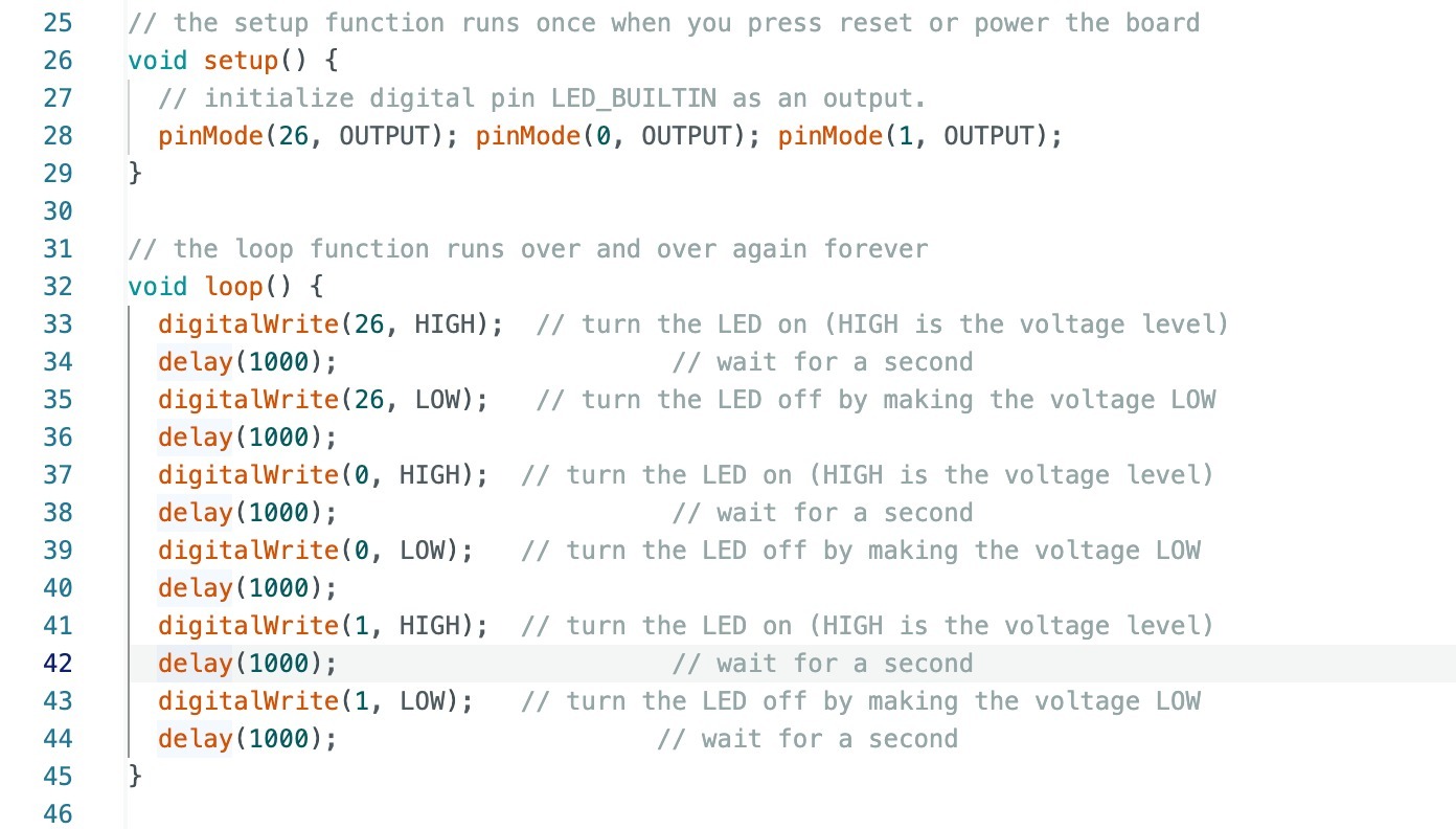
- Click “Upload” button
- The LEDs should start blinking
Testing ESP32 with MicroPython, using Thonny
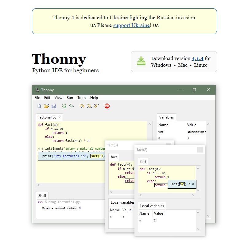
-
Download and install Thonny from Thonny’s website
-
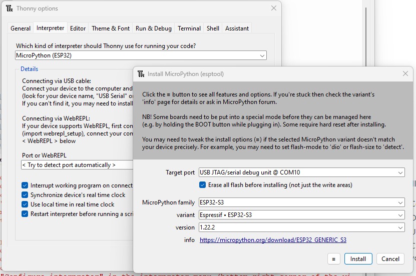
Install MicroPython on ESP32:
- Connect the ESP32 to the computer via a micro-USB cable
- On Thonny, and go to Tools > Options
- Under the “Interpreter” tab, select “MicroPython (ESP32)” from the dropdown.
- Click “Install or update firmware” and follow the instructions to install MicroPython on your ESP32
-
Select the appropriate COM port for the ESP32
- Write and verify the code
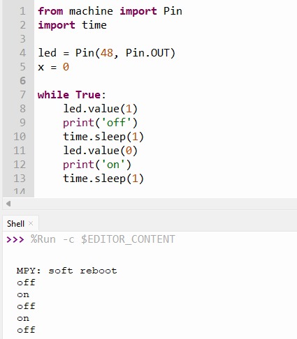
- Click “run the current script” button
- The LED should start blinking