Week 10 - Árbol, a self-tunable multi-instrument
Video
Tasks
This week’s assignment included the following tasks:
Mechanical Design (part 1 of 2)
-
Group assignment:
- Design a machine that includes mechanism + actuation + automation + application
- Build the mechanical parts and operate it manually
- Document the group project
Machine Design (part 2 of 2)
-
Group assignment:
- Actuate and automate your machine
- Document the group project
-
Individual assignment:
- Document your individual contribution
Concept of Instrument machine
Our initial idea was to build an instrument from a guitar string that plays autonomously and replicates the frequency of the played guitar string through a visualizer.

We outlined the various tasks in a brainstorming session: 1. Motor and gearbox
-
Electronics (frequency detection and electronic board design)
-
Housing construction (frame to hold the machine and resonant chamber)
-
Display (to show the detected frequency)
Depending on our availabilities over Easter, we started working on it.
Motor and gearbox
We created a prototype of the gearbox. We built a test gearbox that can house either a 9V DC pololu motor or a 35mm stepper motor. It has openings to mount gears in different combinations, to test different reduction ratios.
It’s laser cut in acrylic, with axles in 1.6mm thick brass.
We used this website to create the gears: https://www.food4rhino.com/en/resource/gearfromcircle-geargen
We tested it with gears cut in waste PCB material, but the gears were too small. It was hard to get them to mesh and they could flex out of alignment. We decided to move to acrylic, and that required an increase in the size of teeth but worked very well.


After testing, we decided that we wanted to cut and create the gears and the box in acrylic. For the cut, we had to adjust the file. We created various versions. Initially, we had difficulties because the cutter did not cut through the acrylic sheet. But after using a different laser cutter, it worked. We also had to extend the teeth of the gears to make them fit better together.
The design envisages the motor below the gearbox. It moves the gears, which ultimately move a component of the guitar to which the guitar string is attached. It was important that all elements are precisely attached to avoid excessive movement. Despite precise measurements, it took us a while to cut them exactly and assemble them.


Electronics
Maxence & Dani are working on the electronics.
The board needs to house - A processor powerful enough to analyze sound and extract its dominant frequency in real time. - Programming connections (eg JTAG) - A power source that can control a 9V motor. - Connections for a stepper motor - A power source that can feed a strip of LEDs and switch them on and off at frequencies (100-1000Hz aprox) (optional, but good to have it in case we do arrive to that point). - Connections for an LCD screen. - Connections for a potentiometer and a button, at least. - LED status indicators.
Design process
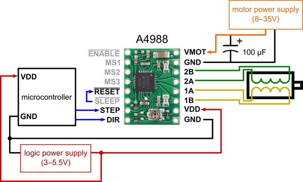
We need to integrate a stepper motor driver into the board. The fastest way to do this is to use an A4988 breakout board, which we have on hand.
We will need to supply it with adequate voltage: 12V or more.
- Mounting holes size: 3.2 mm diameter.
Cutting
The board needs to be double sided so that the stepper motor mount can be soldered.
The process is:
1. Front copper with 1/64 endmill 2. Alignment holes with 1/32 2b. Stick pins into sacrificial board 2c. Cut pin heads off 2d. Lift board, remove double sided tape, apply double sided tape to the other side, reset carefully using the pins as guides 3. Back copper with 1/64 4. Holes with 1/32 5. Outline with 1/32
In between each step Z needs to be rezeroed but the XY reference has to be kept constant throughout the process.
The first version of the board didn’t work as expected so we dropped the custom board requirement and used a dev board we had previously made.


Housing construction
For the resonance box, we decided to build a wooden box. The wooden box should fulfill the following tasks:
- Form a resonant chamber that amplifies sound
- Hold the motor and the gearbox
- Serve as an attachment for the string
- Hold the bridge to allow the guitar string to pass over it
We started designing the box in Fusion. To cut it with the CNC machine, we need to edit it later in Rhino CAM.
We worked on an initial sketch with Fusion. We used sketch mode and the parameter option to easily change individual parameters later if necessary.
We prepared the hole sketch and also some pieces to do a joinery test.
The following steps must be carried out to prepare for the CNC cut:
- Save the Fusion file as a DXF file
- Open the DXF file in Rhino
- Prepare the cutting plan - important: connect all individual parts using the “join” command
- Save the Rhino file as a Rhino 5 file
- Open the Rhino file on a computer with Rhino CAM and prepare it for cutting
- First, set points for the screws
- Then adjust all parameters for pocketing and cutting
- First, save the screw file as a post
- Then save all other files as posts
We initially tested the joineries. Some of the parts fit very well, while others needed adjustments.


After that, we adjusted the cutting plan and cut out the complete box.
Display
Pinout taken from LCD with Arduino
Due to running out of time, we had to leave the LCD out of the first prototype. Now we can’t show the detected frequency.
Final prototype of the instrument
This is what the final prototype looks like!

As you can see, the gears are presented in a visible box made with PMMA where the string is attached too. On the other side of the frontpanel of the instrument, the string is attached and stretched over a bridge.
Next to the circular opening in the frontpanel, there is a potentiometer where you can change the tension of the string by turning it clockwise to increase the tention or counterclockwise to decrease the tention. By playing with the tention you also change the frequency of teh string. This means that you can reach high notes and low notes on the same string!
Inside of the box you can find the hidden electronics.

Improvements next prototype
For the next prototype, we would like to add several features to this project:
1) A more compact and silent motor
2) Frequency detection algorithm using a Fast Fourier Transform to automatically adjust the string tension to tune the string to a given frequency
3) A built-in analog preamp with a 6.35mm jack output to output to a guitar amplifier
4) A LCD display to show the current frequency as well as the desired one, that can be selected with a potentiometer
5) LED lights that respond to the detected frequency
6) Making an upright model that can function like a cajon (percussive instrument)
7) Having built-in effects processing so we can run the output through some DSP effects
8) More strings!
9) Built-in power supply instead of having to plug USB for microcontroller as well as 12V for the stepper motor
10) More compact and acoustically-minded box design
And some dream features…
12) Built-in speaker and amplifier circuit to output audio directly
13) Eurorack interface built-in to plug in a modular synth directly