8. Electronics Design
Task
Use the test equipment in your lab to observe the operation of a microcontroller circuit board (as a minimum, you should demonstrate the use of a multimeter and oscilloscope)
Multimeter
We observed the operation of one of the microcontroller boards that we designed this week.
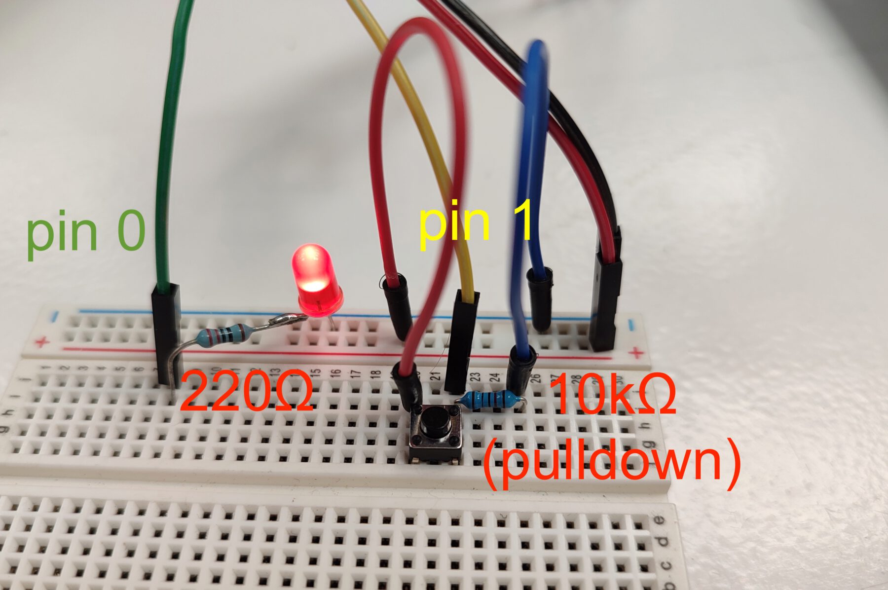
We observed the voltage change on the pins as we executed a blink sketch. A button, connected to pin PA01, was pulled down with a 10k resistor. An LED was connected to pin PA00 with a 220-ohm current-limiting resistor.
`blink_button` sketch. Click to show code
// board_02
int LED = 0;
int BUTTON = 1;
int start;
bool state;

void setup() {
  pinMode(LED, OUTPUT);
  pinMode(BUTTON, INPUT);
  Serial.begin(115200);

  start = millis();
  state = false;
}

void loop() {
  int now = millis();

  if (now - start > 100) {
    int pressed = digitalRead(BUTTON);
    Serial.println(pressed);
    Serial.println(state);
    if (pressed) {
      digitalWrite(LED, state);
    }

    start = now;
    state = !state;
  }
}
When on, the voltage drop across the LED was 2.07V while the drop across the resistor was 1.03. This adds up, more or less, to the 3.113V supplied by the MCU (an ATSAMD21E18A) through pin PA00.
Oscilloscope
The oscilloscope we have in the lab is a DSO Nano v3.
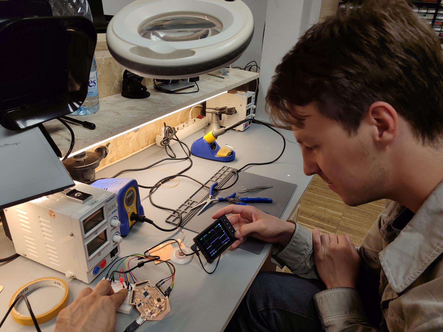
We observed with it the operation of the same board running the same sketch.
You can clearly see the 100ms pulses.