3. COMPUTER-AIDED DESIGN
This week I learned to vectorize images. I have developed a solid 3D model with CAD software in which I tried to represent the design of my final project. I have made an animation that simulates the operation of the safety device that I want to make as the final work. I have used a video editor to process the rendered animation.
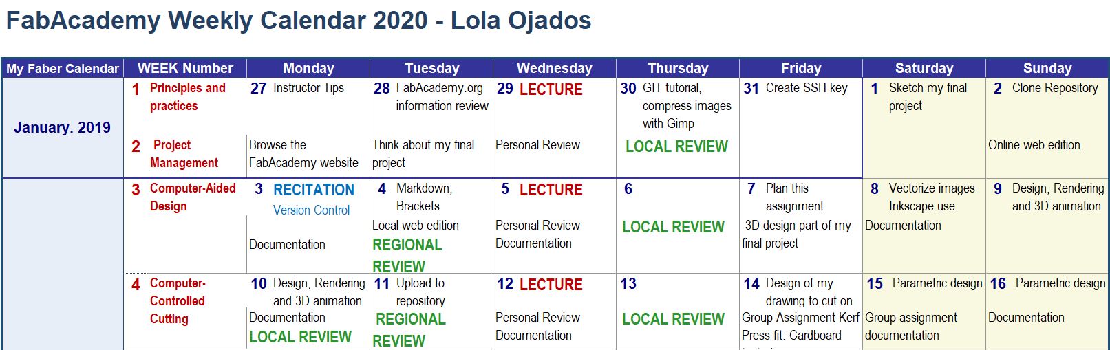
I have continued using my weekly planning in which I have updated my activity in FabAcademy
This has been my sequence of work during this second week developing assignment 3:
07/02/2020 I started planning the task of week 03 and designing my final project in 3D.
08/02/2020 I learned to vectorize images with Inkscape and I practiced with this software.
09/03/2020 I continued with the 3D design, and started with the rendering and animation testing several softawares.
10/02/2020 I continued with Design, Rendering and 3D animation, I have the documentation in process.
11/02/2020 I finished the documentation and uploaded the repository.
3.1. Convert a raster image to a vector image
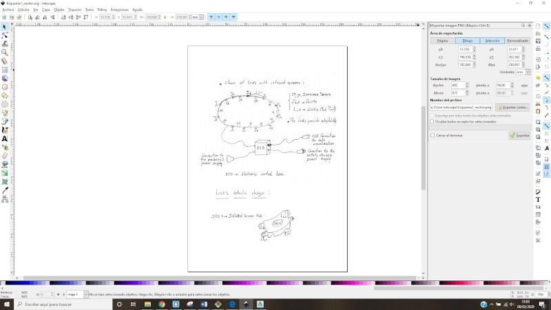
To document the vectorization process of an image, or step from raster image to vector image, I am going to use the Inkscape program, which I install on my PC.
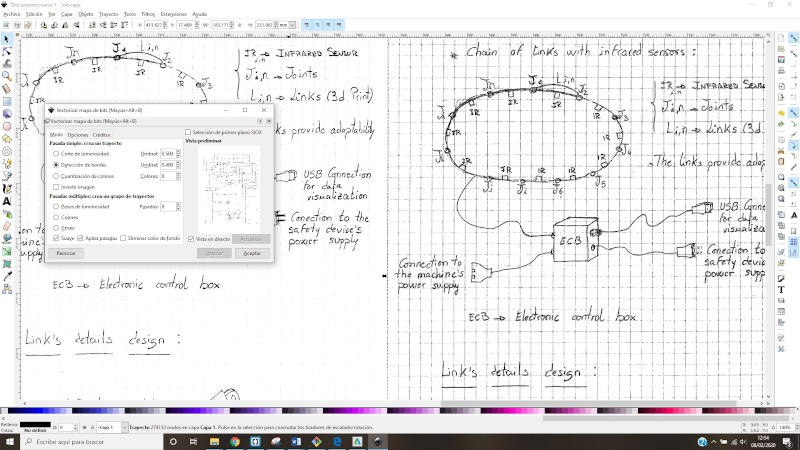
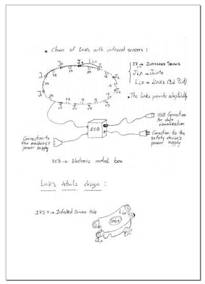
I open this program and import the image of the initial scheme of my project, which is the one that I am going to use to do these tests.
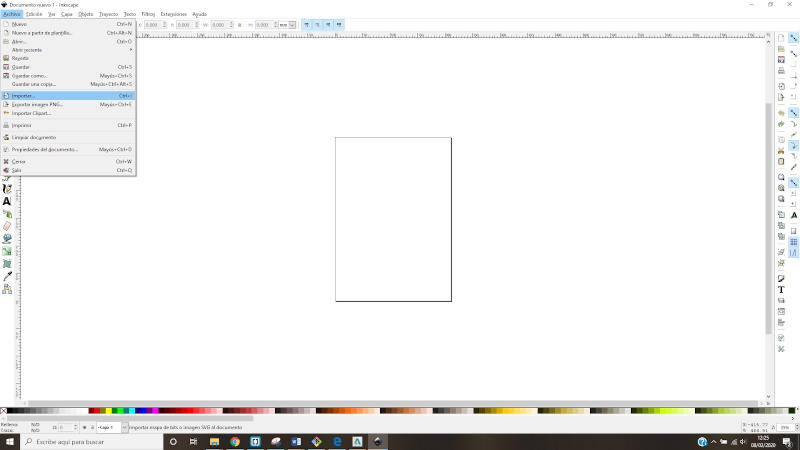
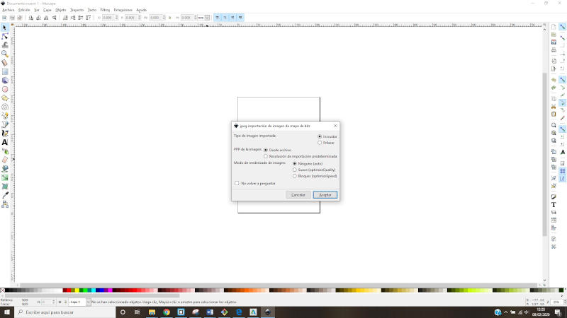
I leave the import values, by default.
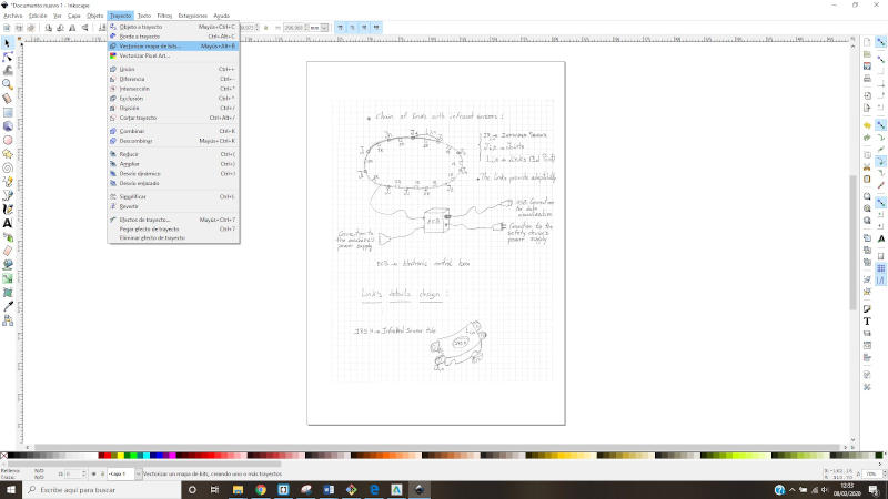
With the “+” button or with the “-” I zoom in or out.
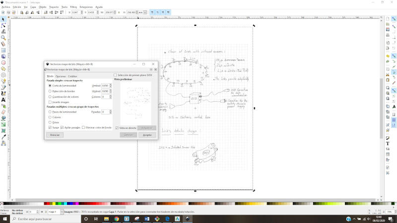
With the image selected, inside the path blind, I choose the option “Vectorize bitmap”
With the first option “Light cut” with the value of 0.45 by default, if we have the option of live view checked, we see a preview:
Accepting and moving the result that is superimposed on the initial image would look like this:
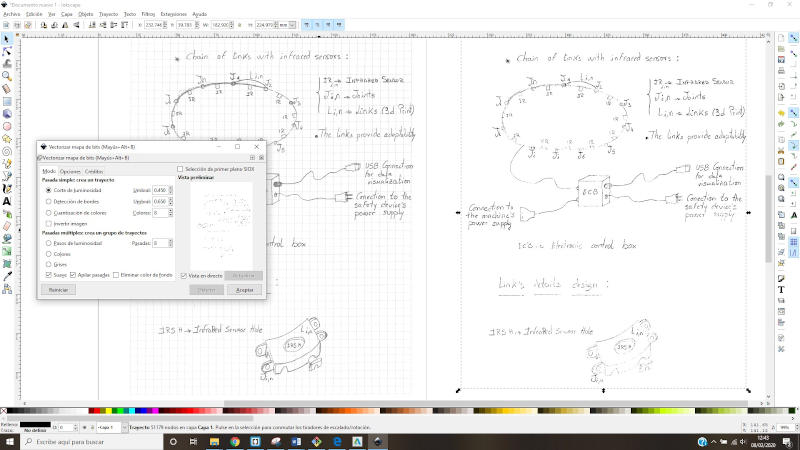
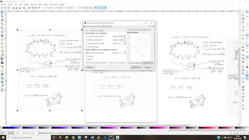
I raise the threshold value in light cut from 0.45 to 0.60 now, and the result is this: It improves but you start to see the squares of the paper.
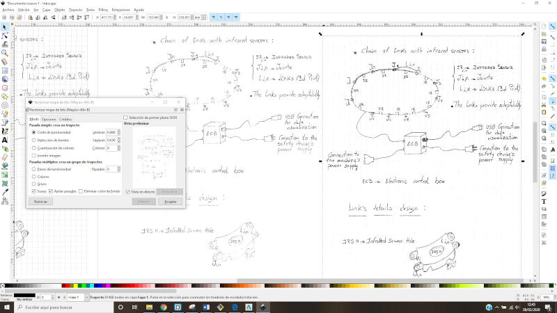
To try to avoid seeing the tables, the threshold value for brightness cut now put it at 0.5 and it looks like this:
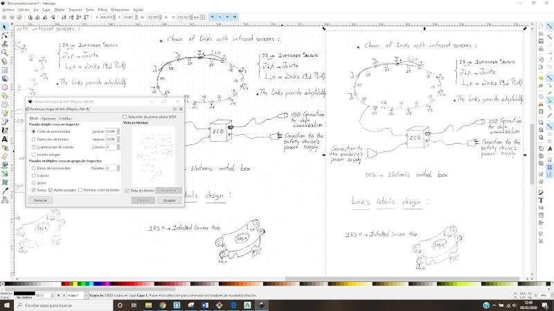
Now I lose more information than I want, since it started from an image that is not easy to vectorize, but still the result for my objective would be valid. I visualize the scheme and I have obtained a vector image.
I try more options:
In this case, the edge detection option with a threshold value of 0.4, and the result is the one seen farthest to the right, the background frames are too visible.
I try another option, brightness steps, I leave the default threshold value:
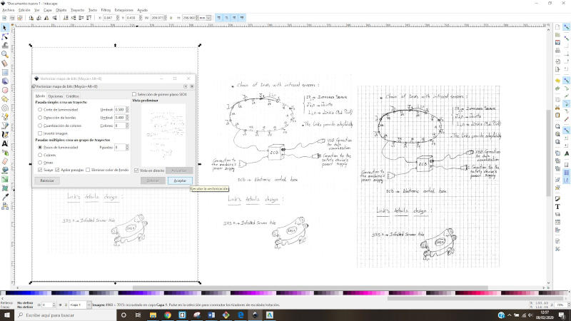
The result is that of the Left:
I’m left with the result that was closest to what I’m looking for, and I save as. The extension is Inkscape (svg):
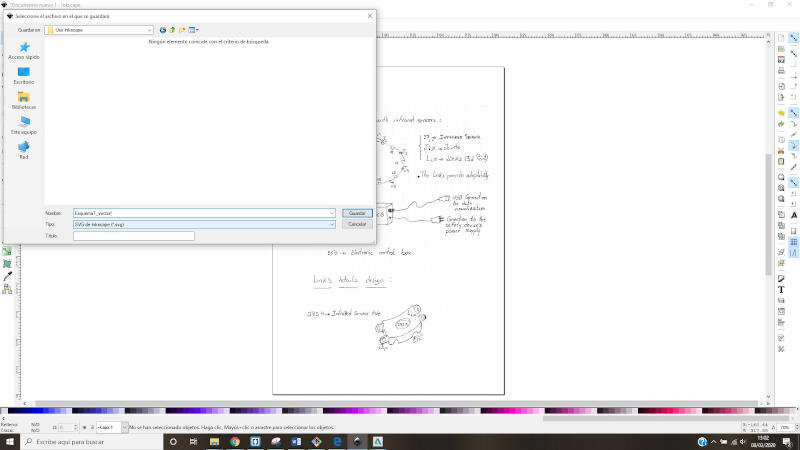
I try to export as a png image:
I leave the default values and it looks like this:
3.2. 3D Design of my idea to Final Project
Basic Component
This week I have developed my final project in CAD, I have tested with FreeCAD or Blender, and finally I have chosen SolidWork for the 3D design and for the animation 3DSMax. One of the reasons that I have use SoliWorks is that I know well this program, and I can use the generated files in my CAD classes and in the subjects in which I teach (ORP). I can also export to several formats and that can be useful as you move forward in this week’s assignment. So, I have optimized the CAD development time too…
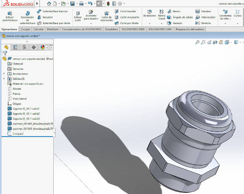
For this first design, I used the part module and created different 2D profiles, from which I added and removed material with commands such as extrusion, revolution, or extrusion cutting…
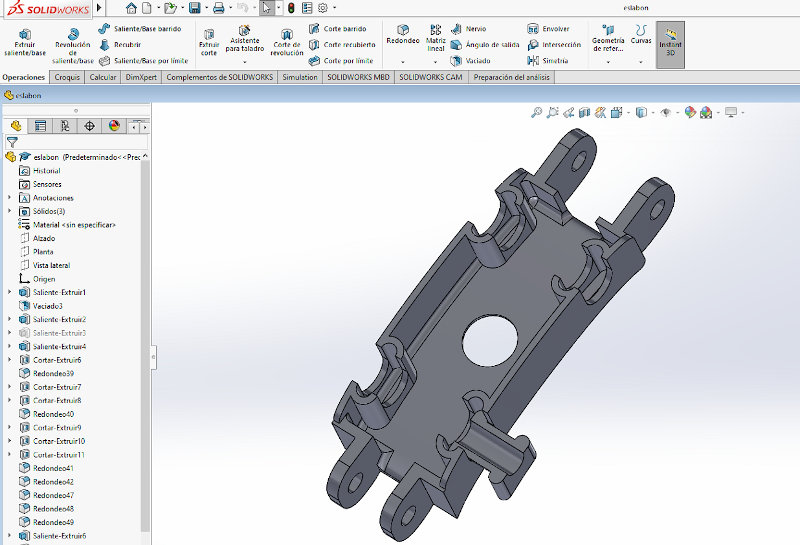
I show some images of this process in the solidwoks interface.
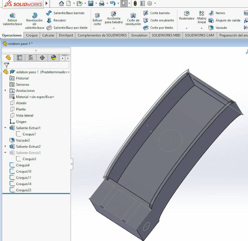
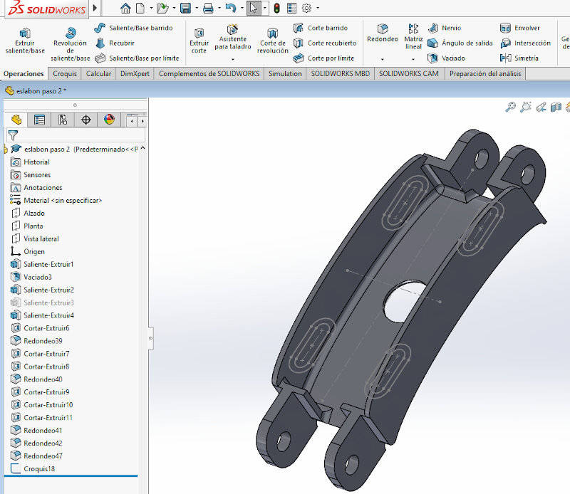
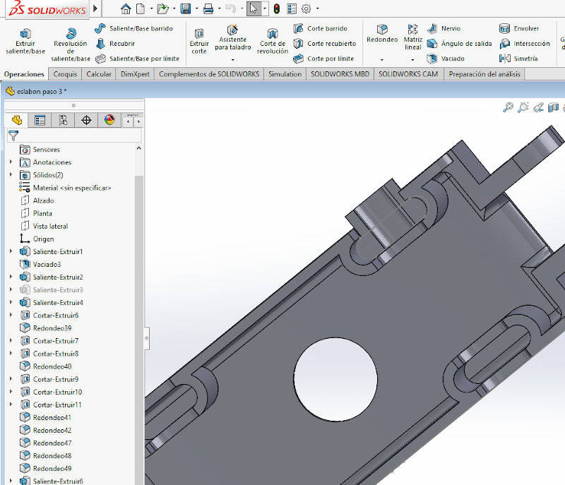
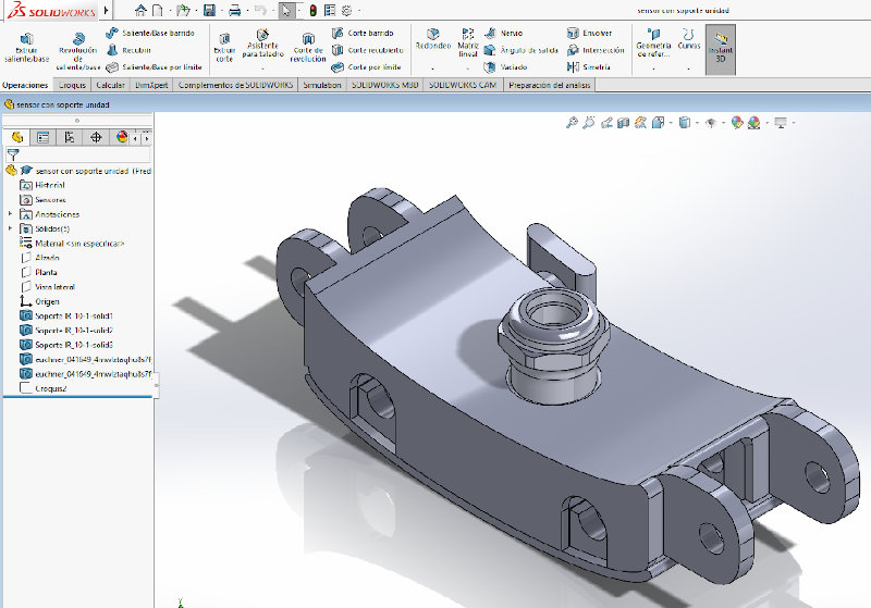
This is the initial basic piece designed and finished from different points of view.
The SolidWorks and stl files of the model can be downloaded here:
infrared sensor support or link(sldprt)
infrared sensor support or link(stl)
More pieces of my device
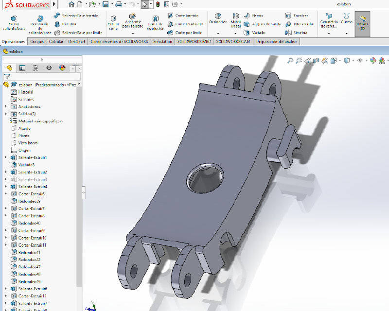
I have designed a cover so that it fits in the base piece and inside the cables, the sensor, and the different components that I discover are necessary. This is de Cover part designed.
This other piece represents the infrared sensor that will be installed in the links.
Component assembly
First I create an assembly with the components of a single link, so you can see how it would be. For this I have used the SolidWorks software assembly module for the same reasons that I wrote previously.
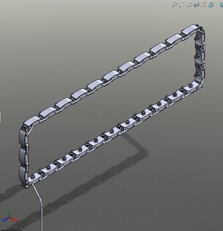
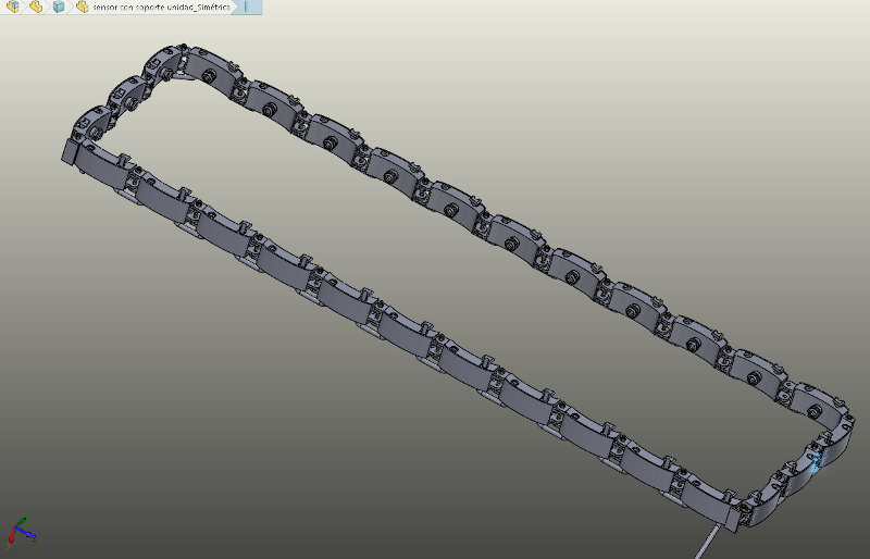
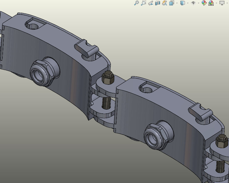
To join the links and shape a chain that can be placed in the danger zone of a machine tool as if it were a window and the infrared sensors its glass, that if it is crossed the machine would stop, I have assembled links and I have incorporated screws , nuts and Solid toolbox elements.
The result is the one shown in these two images.
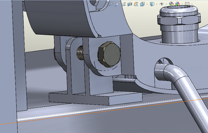
Here you can see a detail of the join between links.
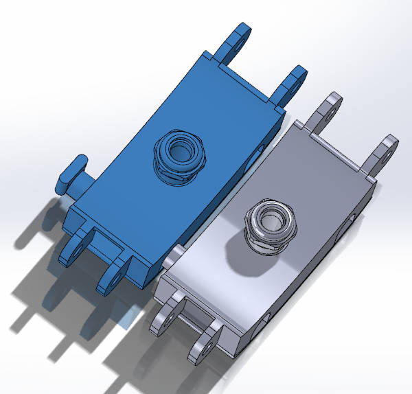
I have designed the base piece with a projection that allows two links to fit in parallel in case at any time it is necessary to expand the width of the window or even create a maya of sensors in two directions. The position of the two links in parallel would then look like this:
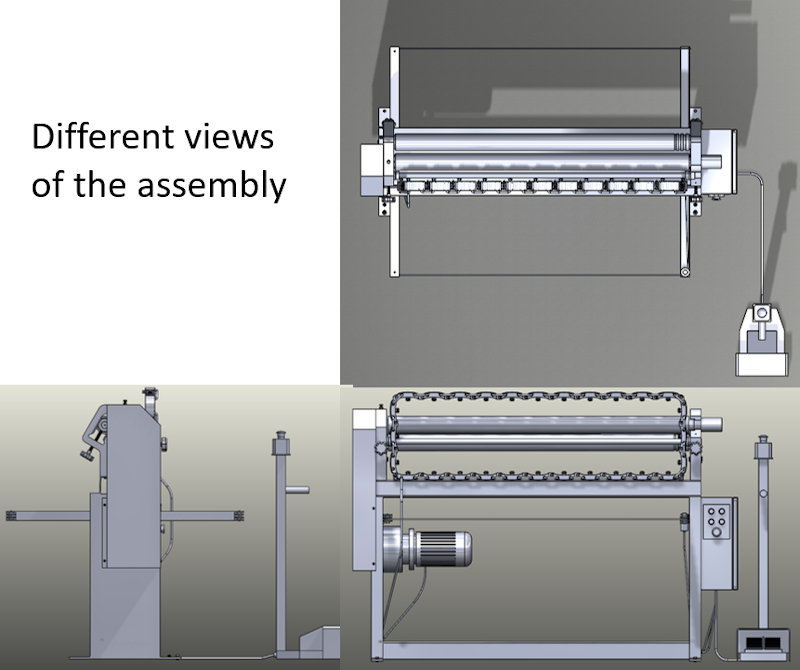
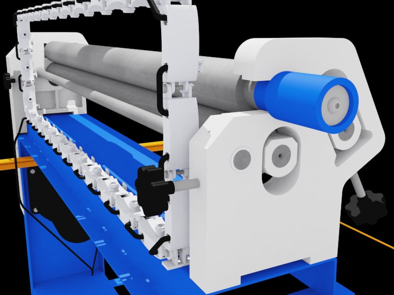
Finally, from SolidWorks I have made the assembly of my safety device (infrared window), incorporated into a machine tool that I modeled some time ago for another project in which I needed a 3D scene of a mechanical workshop.
The machine is a roller bending machine, in which entrapments can occur. There is a danger zone where the accident is most probably to occur causing entrapment damage.
I have searched for a video that I have placed in the assignment of the week01 to better document the justification of my project idea.
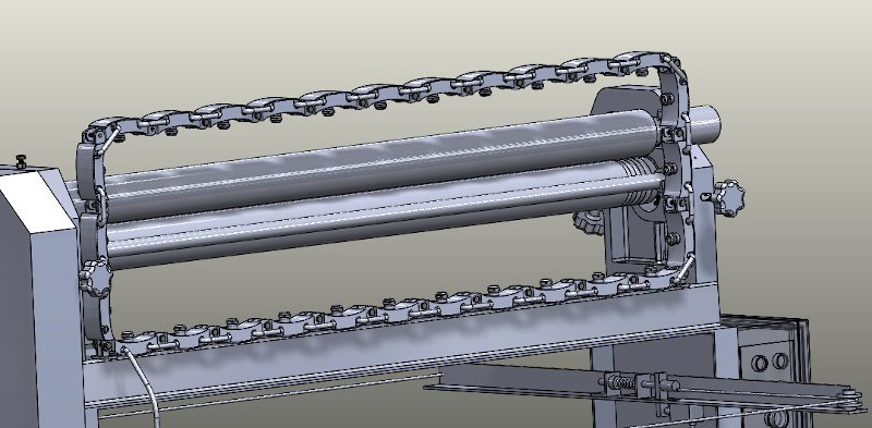
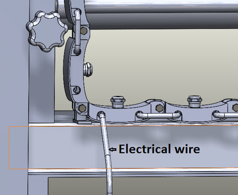
The assembly of the chain with infrared sensors on the bending machine is as follows:
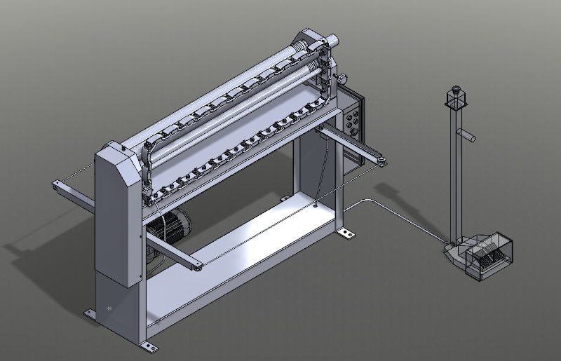
The chain will be located just in front of the danger zone of entrapment of the operator of the roller sheet bending machine.
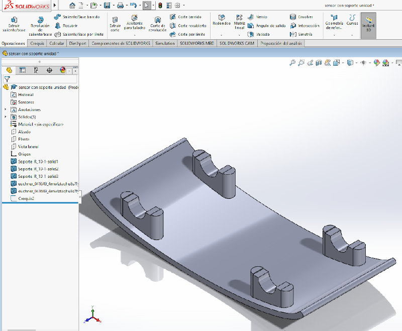
To fasten or support the window to the machine, in principle I designed a fastening piece that has this shape:
The links will be connected in series to the control box.
I hope this whole CAD process serves to show what I really want to develop in my final project. With the initial sketch of the week1 it was difficult to understand my idea, or … that is said. :)
3.3 Viewer for my 3D model
I have worked with Sketchfab and this has been the result.
The .obj file for this model can be downloaded from here: Infrared window model on a roller bender
3.4. Animation of my design
3.4.1. Animation test with blender
I have taken my first steps trying to encourage the operation of the machine with blender. I have come to create a very short video and with not very good results, but the path to reach it has helped me learn a lot of things about this program, which I only used to model on a mesh from 3D scanning for a long time.
To take the first steps and place myself in the objects, I have resorted to this video:
Maybe I can help someone else who is looking to change the pivot point in a reference to an existing geometry in Blender.
This document is also in progress at this time.
3.4.2. Animation and application of textures with 3DS Max
With 3DSMax I have achieved good results. This program is more familiar to me. It still cost me to get to do what I had proposed, but the results have left me very happy.
I finally see the light at the end of the tunnel.
This document is also in progress at this time.
The work process followed in 3DSMax is explained below:
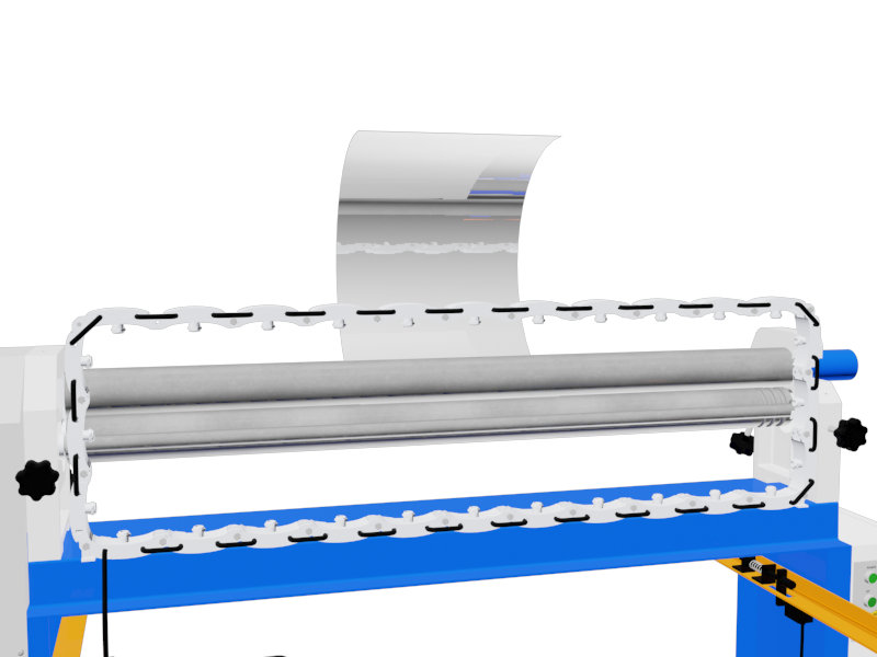
I managed to put a sheet in the scene that curves when it passes through the rollers.
I have included textures and materials to the different parts of the machine and the safety device.
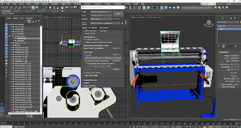
To make the animation of the operation of the machine, I introduce a camera and I will render setup, I set the resolution of the resulting video to 800x600 and I indicate the route in which to save the video in avi format, which is the one available from 3DSMax.
When the video creation process begins, an error appears.
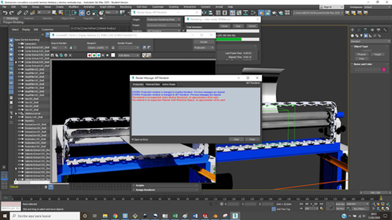
The error is solved using another rendering engine within the same software capable of identifying textures. Because that was the previous mistake. I test with Scanline renderer and with a single frame. Now the frame is rendered correctly.
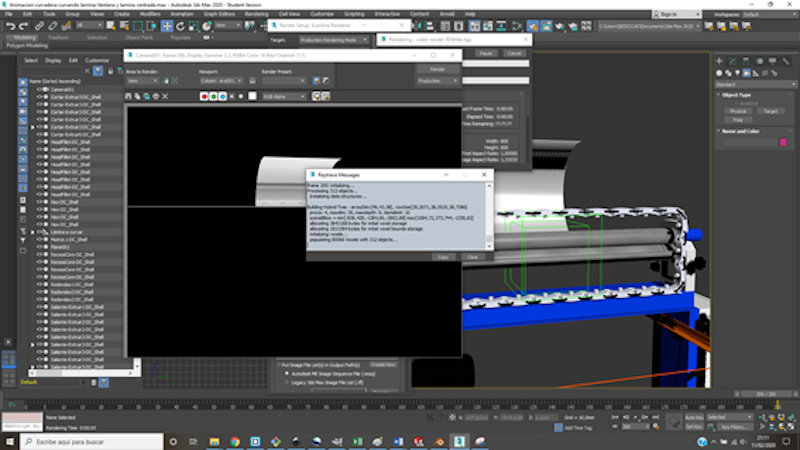
After this I make the complete video in the same way as a single image, with the same render engine and I have the possibility to compress the result. What comes up…
And, after more than two hours, the result is good.
In order to visualize it I have learned to use Vimeo, this will be documented in another section (3.5).
Now I take another step and put a human hand when the machine passes through the window.
I look for the hand on the 3D Warehouse website:
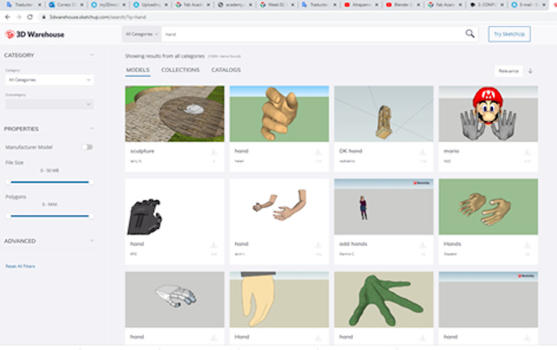
This hand is in .dae format, I import it from the 3DSMax scene. And I give it movement. To do this, I imagine the new animation incorporating the hand.
To create a new video from 3DSMax, from Render Setup I configure the rendering parameters and pressing Render already begins to create this new video that includes the hand and the machine stop when the hand crosses the safety device that occupies the danger zone.
3DSMax tells us how long it will take to render this video. In this case, it will be more than four hours, this is shown in this image:
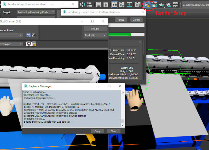
The name of the video being created is: “video render 3DSMax Hand”.
Like the previous one, it is very heavy, so instead of uploading it directly to my repository, I will use Vimeo to view them from the cloud just as I have done with the “video render 3DSMax New”.
3.5. Viewer for my videos
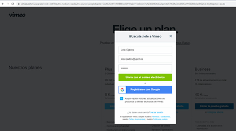
As I explained in the previous point, in order to view the videos from the cloud, I used the Vimeo viewer.
Here I create an account of the Vimeo Basic version (free).- Vimeo
Within my account, I can press the new video button and upload the video that I want to view, from the folder where it is located, I can also select the frame that I want to be displayed when I have it on my website. Click save.
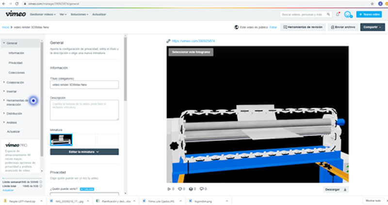
You have to give the “compartir = share” button and copy the link on my website.
This is how I created the link to the videos that can be viewed in section 3.4.2.
I have also installed Open Shot to edit my 3DSMax animation videos.
Let’s see what results I get…
3.6. Links to my files
3.6.1. SolidWorks and .stl files:
Module to support the IR sensor
3.6.2. 3D model with textures:
The assembly of the bending machine with the safety device occupies too much,> 20Mb, and for this reason I have not been able to attach it as a file to the repository, but it can be shown in sketchfab and the drive folder where it is located can be accessed from the section 3.3 of this assignment , here is the model (.obj file) and its textures (.mtl file).
3.6.3. Animations:
The animations are shown on vimeo in section 3.4 of this assignment .