18. MECHANICAL DESIGN, MACHINE DESIGN
The statement of the task to be carried out in this assignment is:
W18 group assignment
-
Mechanical Design
-
Design a machine that includes mechanism + actuation + automation. ✔
- Build the mechanical parts and operate it manually. ✔
- Document the group project. ✔
-
Document your individual contribution. ✔
-
Machine Design
-
Actuate and automate your machine. ✔
- Document the group project. ✔
- Document your individual contribution. ✔
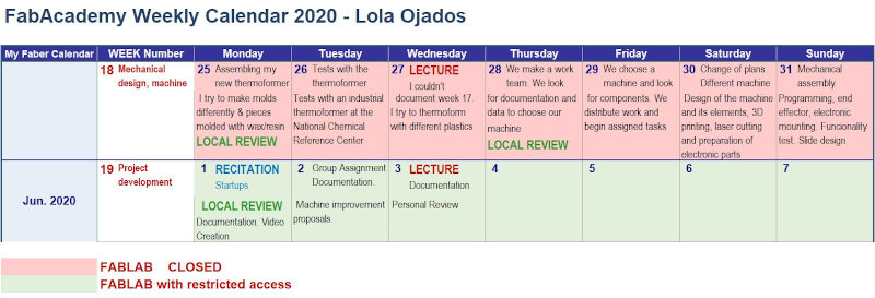
* Like every week. I present my weekly work schedule at Fabacademy.* 😊
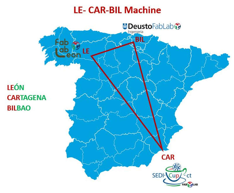
Given the situation of the COVID-19, this year the construction and testing of the machine has been complicated. We have formed a working group from three fablabs in Spain. (León, Cartagena and Bilbao). As we cannot move around Spain due to the state of alarm, we have decided to manufacture the machine in León and where one student will be in the Lab in person and the rest will participate remotely.
Please visit our group website!!
My individual contribution has been:
- Participate in the process of choosing the machine.
- Search for the elements and components necessary to be able to do electronics and programming tests from my physical location, together with my colleague Álvaro.
- Search for useful information and documentation to carry out the mechanical part of the machine.
- Participate in making decisions about the design to materialize.
- Give remote support to the elaboration of the mechanical design developed by my partner Adrián from León.
- Assist remotely the assembly of the machine components manufactured by Adrián, the programming tests and its start-up process with the program made in Cartagena, after integrating the end effector module designed by my colleague Iván from Bilbao.
- Design, configure and shape the machine’s Summary Slide.
- Collect videos and images for the assembly of the summary video edited by Iván.
- Document and format the documentation of the group assignment, making the distribution of the information in sections and collecting in them the work of each of the four participants who have formed a team to manufacture a working mechanical machine.
*It has been very satisfying to work as a team, to be able to manufacture the machine in record time, in special circumstances due to the pandemic, from different geographical points, to be able to learn from my colleagues, each contribute their knowledge and share it with others, and of course that the four of us together have achieved a good operation of it. I am very grateful to my colleagues, very proud of the result obtained, and happy to have been able to collaborate in this project. *
* Adrian, I have to tell you that “you are a good leader”. *
18.1. Introduction
This time, the challenge posed in the weekly assignment is to develop a machine capable of performing a function.
To do this, we have formed a work team to shape this task, the team participants are:
- Adrián Torres Omaña, from Fablab León


- Iván González Alonso, from Deusto Ingeniería Fablab


- Álvaro macián Morales and Lola Ojados González, from Sedicupt-FABLAB


The first thing we tackled was to make the decision about which machine it was that we want to develop, with the resources available in the different FABLABs from which we work, and to which we are having access, still restricted, due to the COVID19 pandemic and plan later the execution phases, from design to manufacturing of the necessary parts, assembly, programming, simulation and performance testing.
To do this, we created a WhatsApp group where everyone could contribute their ideas and we held several video call meetings where they could present them.
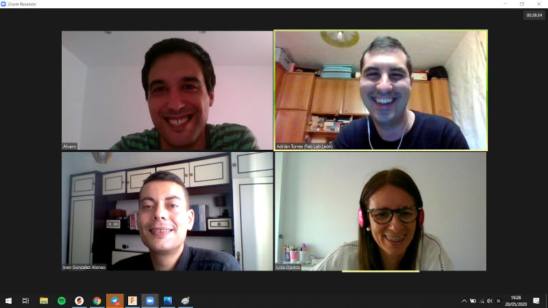
After the Lecture on Wednesday, May 27, our colleague Adrián Torres, face-to-face student of the FABLAB León node, from whom we are doing this Fabacademy 2020 training as remote students Álvaro and me, and that also supports Iván de Deusto Fablab, led the group and we take a good rhythm of work.
We made distribution of tasks and we was decided who carried more weight in each of them, this distribution was more or less like this:
HOMEWORKS:
-
Design / Assembly: Adrián
-
Electronics / Programming: Álvaro and Iván
-
Documentation: Adrián, Álvaro and Lola
-
Slide / video: Lola
18.2. Choice of machine
With the resources available at the central node FABLAB León, we think of different possibilities.
We studied the machines developed by Fabacademy students from previous years and, apart from that, we explored other possibilities, with this, we made a list of possible machines to develop this course for us that remained this way.
LIST OF POSSIBLE MACHINES 2020:
-
2D drawing machine with two axes (gestalt modules from Nadya) (supported by a bearing) (+link)
-
Pick and place. Three axes. (Nadya modules) (Arduino + ramps)
-
Respirator with an AMBU
Of all of them, those that are marked in bold are the ones that we found most feasible.
Finally from all of these ideas, we chose the last option on the list, JAKE READ MACHINE .
Both for the choice of the machine and to know the operation and the steps to follow for its development, it was useful to consult the following links as supporting documentation .
-
DOCUMENTATION BASED ON THE MODULES THAT WERE MADE IN 2016 AND 2019
-
INSTRUCTABLE 4xiDRAW (It is a drawing machine that is very close to what we want to do in this assignment).
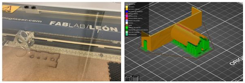
We started by identifying which parts would need to be designed and printed in 3D for the machine and thinking about what programming to incorporate.
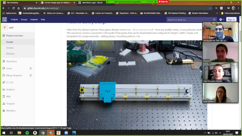
Our machine will look something like this:
We have decided its name, it will be called “LE-CAR-BIL MACHINE” (León-Cartagena-Bilbao), our triangle / alliance has been formed. “Union make force”
Adrián starts with the design and simulation of the machine.
The gray pieces are incorporated on the structure of the machine from which we started, and also the legs and the connecting piece of both modules
Iván designs this piece (tool-holder) that will be adapted to the drawing tool (pencil for example) that will follow the programming that we develop.
At this point everything is optimism, but, * “the problems” * appear, and because we do not immediately find accessible or affordable bearings that are inserted and can be adapted to this configuration of the machine, we have been forced to change plans and we are going to use Nadya’s modules . This only affects the structure, but not our mechanism, the change is the substitution of some materials or mechanical parts for others, but it does not affect the tool holder designed by Iván or Álvaro’s programming.
We will use the Nadya modules for the structure, Iván’s tool-holder / end effector and for the electronics and programming part we will take into account that it will be made up of RAMPS + Arduino + 2steppers.
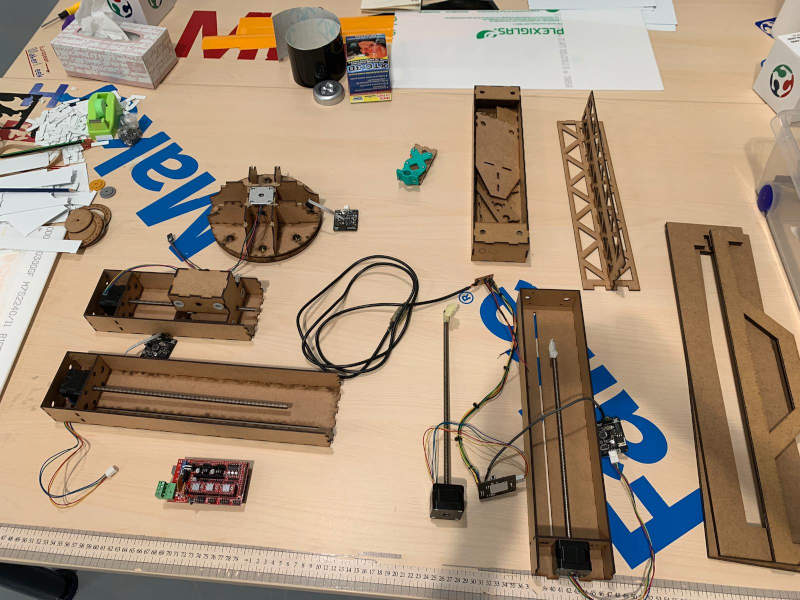
From Cartagena Álvaro and I, we managed to locate the necessary electronic materials that will be used in the machine to mount them in our Fablab in Cartagena and to be able to test the programming with them.
They are the same components that Adrián has in León, and that will form part of the assembly of the machine.
Now this sketch shows our new idea.
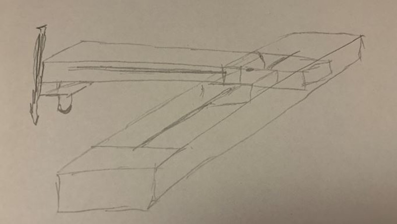
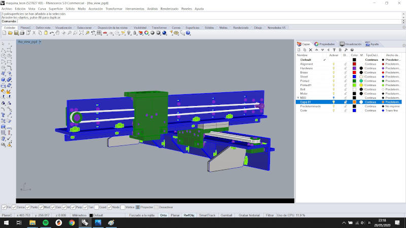
The design of our machine after the change of plans is this:
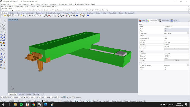
* Now it’s time to materialize this idea and make our machine a reality. *
18.3. Design and Assembly
This part has been developed by Adrián Torres, for more information visit the Mechanical Machine Assignment on (Adrián’s Fabacademy website)
Here is included:
- Mechanical Design
- Fabrication and Assembly
- Mechanical Movement: Operating it manually
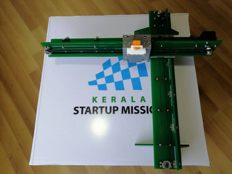
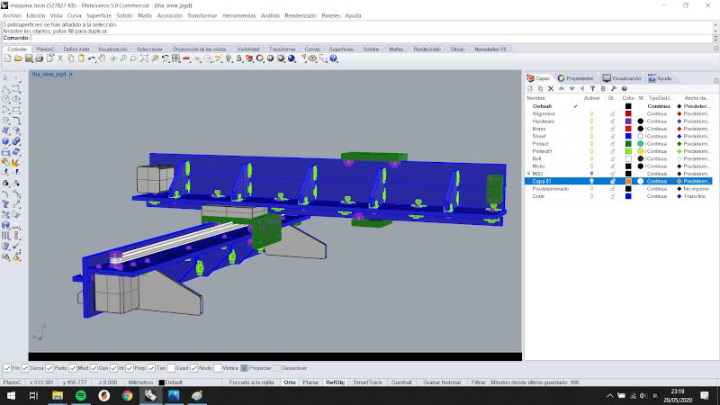
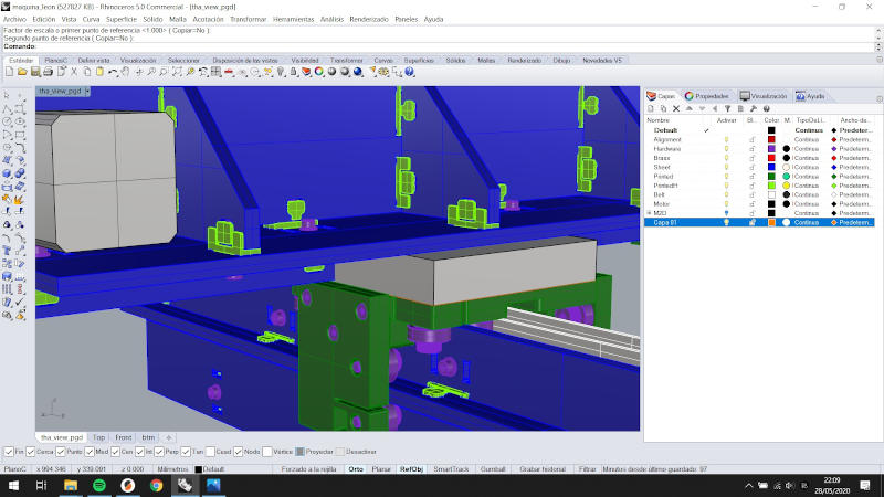
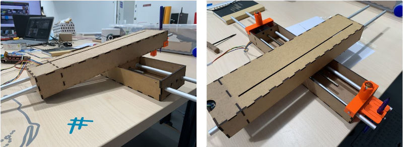
The design consists of a module for the X axis, a module for the Y axis with a union connector for both axes.
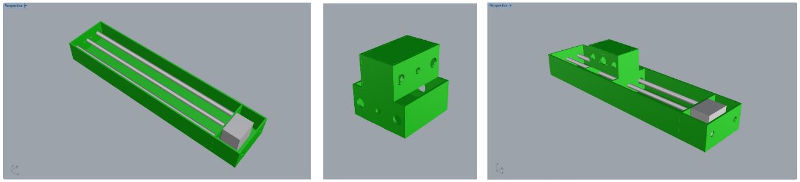
With Adrián’s adjustments, the design of the set looks like this:
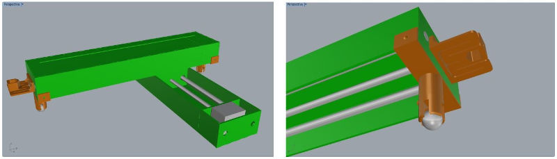
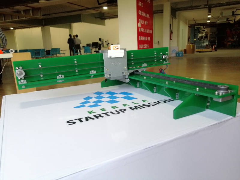
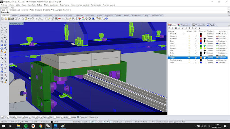
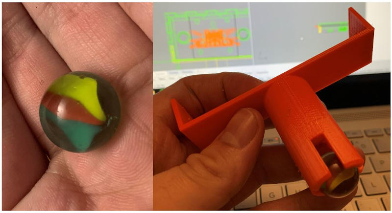
I thought it was great to use the marble as a bearing for the part that was cantilevered and had to be given a mobility solution.
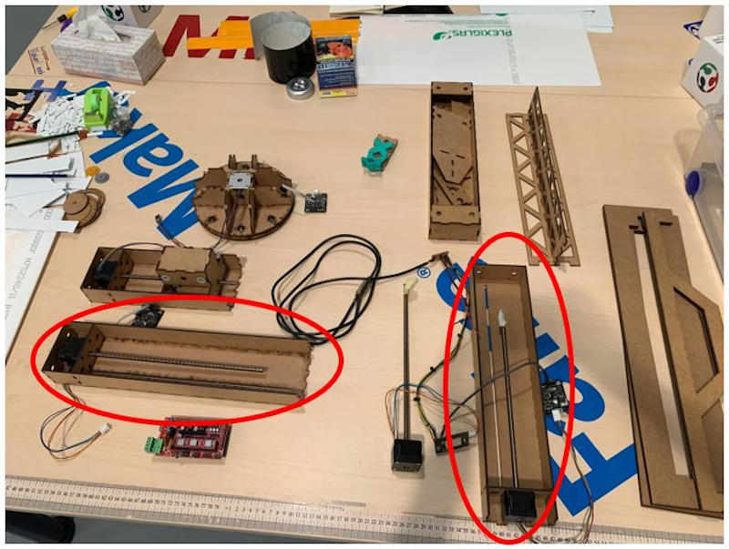
For the manufacture of the parts that make up the machine, laser cutting and 3D printing have been used.
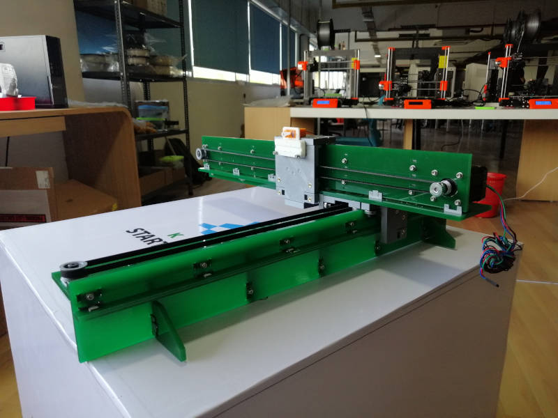
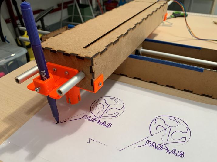
The assembly looks like this:
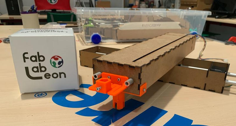
Finally, mechanical movement was verified by manual operation of the machine.
And it worked !!!
18.4. End Effector
This part has been developed by Iván González, for more information visit the Mechanical Machine Assignment on (Iván’s Fabacademy website) or/and (Adrián’s Fabacademy website)
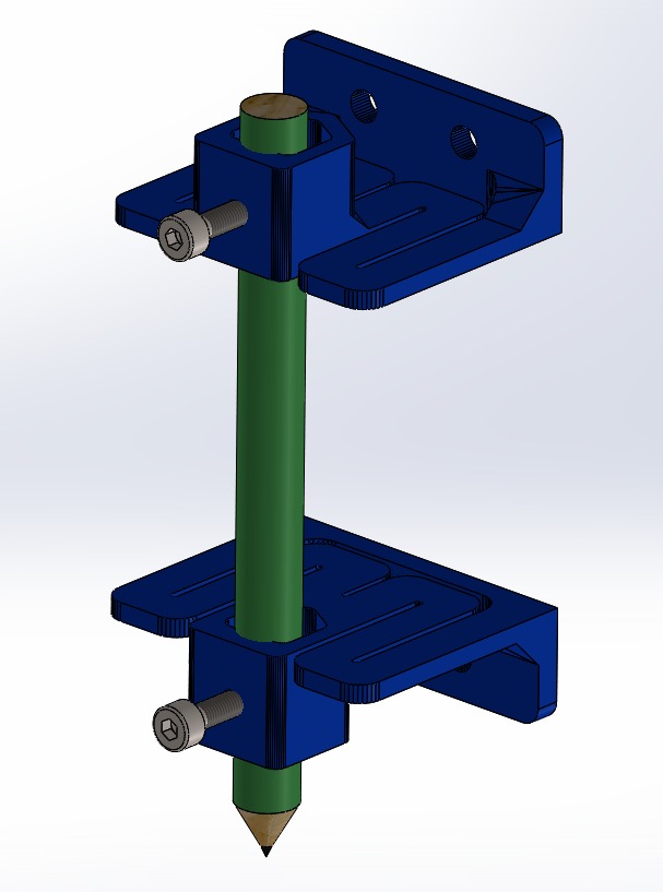
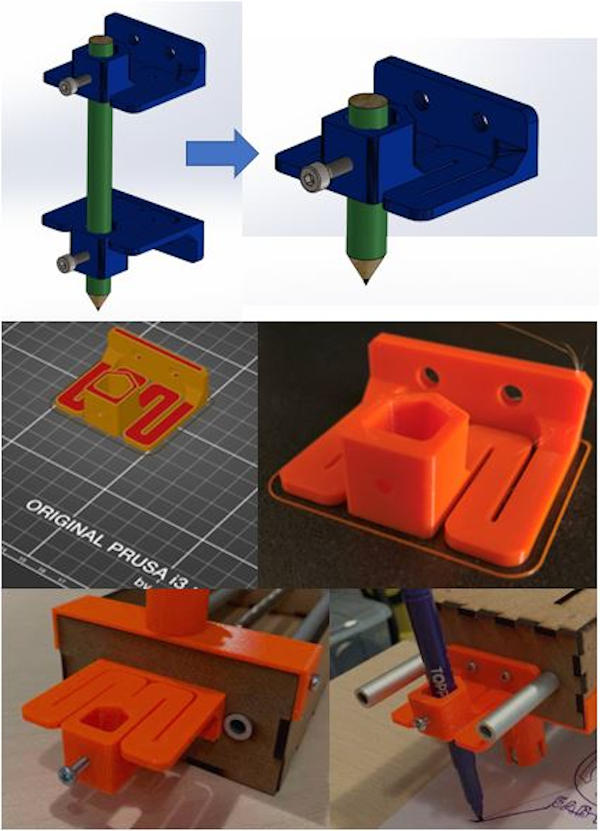
Iván has carried out the mechanical design of the tool holder.
To design the tool holder, it was originally thought that it would have two heads for greater stability, which would be mounted on the Z axis, symmetrical with respect to the X axis, but when changing the initial design of Jake modules to Nadya modules , only one has been placed for reasons of space.
The tool holder continues to fulfill its function and is suitable for all types of markers since it has an adjustable diameter by means of a screw. It has been printed in 3D.
18.5. Electronics
This part has been developed by Adrián Torres in León, and replicated by Álvaro in Cartagena to test the programming.For more information visit the Mechanical Machine Assignment on (Adrián’s Fabacademy website) or/and (Álvaro’s Fabacademy website)
The electromechanical components used in our machine are:
- 4-wire threaded rod
- Arduino Mega 2560
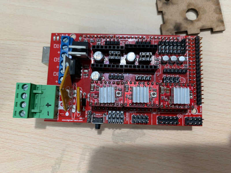
- Ramps v1.4
- Drivers Polulu (HR4988)
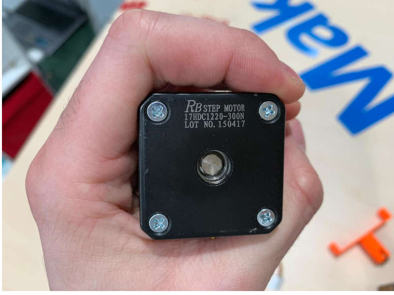
- RB step motor 17HDC1220-300N
- Power supply, 12V 10A
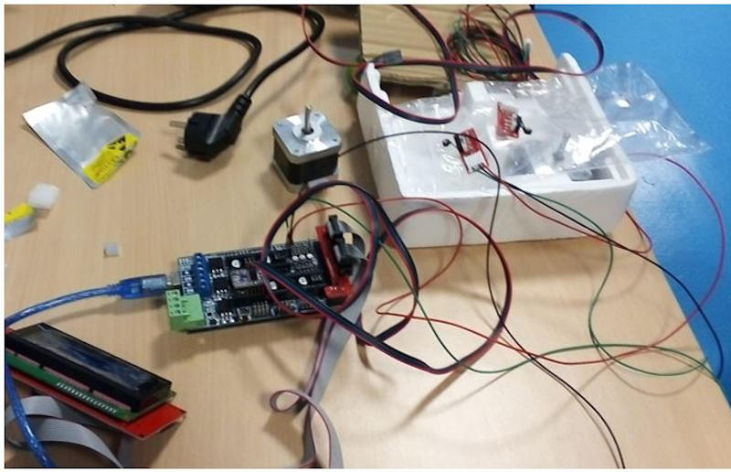
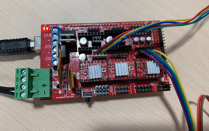
After programming Arduino Mega 2560, the RAMPS module is connected where there are three Polulu controllers (HR4988).
Only two axes will be used, X axis and Y axis. According to the GRBL software configuration, this connection is on the X axis and on the Z axis, so the change of axis will be modified in the code.
RAMPS is powered by a 12V, 10A power supply.
This is the physical connection:
18.6. Programming
This part has been developed by Álvaro Macián in Cartagena, for more information visit the Mechanical Machine Assignment on (Álvaro’s Fabacademy website)
To be able to program, I located in Cartagena, electromechanical components as similar as possible to those that Adrián had in León.
Álvaro used these components for programming and subsequent testing:
-
Ramps v1.5
-
Drivers Polulu (HR4988)
-
HTA3D step motor 17HS4401
First, we decided to use a firmware to control the machine.
This is a list of the most used firmwares for 3D printers and CNC machines.
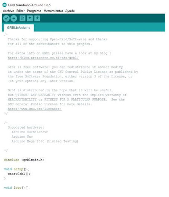
In principle, we choose the GRBL firmware (downloadable here) because it is easy to configure and can be controlled using the Universal G Code Sender software that can be downloaded at this link. (To run it, JAVA must be installed).
The downloaded firmware is the update of the previous one, and gives problems when installing it, so you have to download the initial version and then update.
By loading GRBL to Arduino Mega using a script (without connecting the Ramps for security), and trying to move the motors from the Universal G Code Sender, we are not successful. So you have to try to change the code of this firmware to work with the Ramps.
Looking for solutions we discovered that there is a GRBL firmware version for Arduino Mega and Ramps. This is the link, which we load in Arduino.
Álvaro does not have any problem, but compilation errors appear to Adrián and Iván and the system.h file cannot be found. Adrián from León solves it using the super computer of our instructor Nuria in León, and manages to load the firmware in Arduino.
After this, we connect the Ramps (with the connected drivers and motors) to the Arduino and we also connect the power supply.
We open the Universal Gcode Sender and this software connects to Arduino. The motors are verified to work, but the firmware must be configured correctly so that the movement of the machine responds to the distances indicated by us.
We do not have the data sheet for the threaded rod and motors, so we consider some initial parameters for the threaded rod supply and motor steps per turn. These parameters are corrected after doing a cross multiply, and we ensure that the movement of the motors makes the carriage move correctly.
The Universal Gcode Sender software allows us to use a Gcode to move the machine. We tried to use Mods to generate a Gcode, but it doesn’t work properly. Also, we realize that we have swapped the z and y axes. We changed them on the Ramps to fix it.
But that Gcode keeps doing weird things. So Álvaro comes up with using Cut2D / Aspire software, which we normally use in our Cartagena Fablab to generate Gcodes in our circuit milling machine.
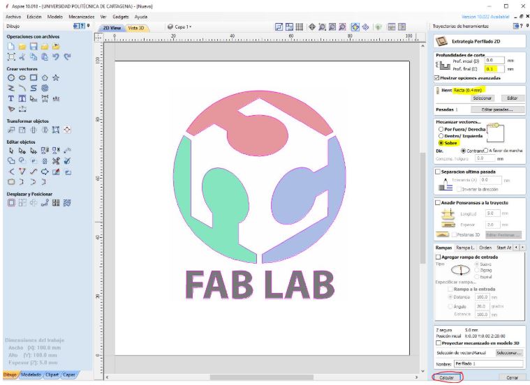
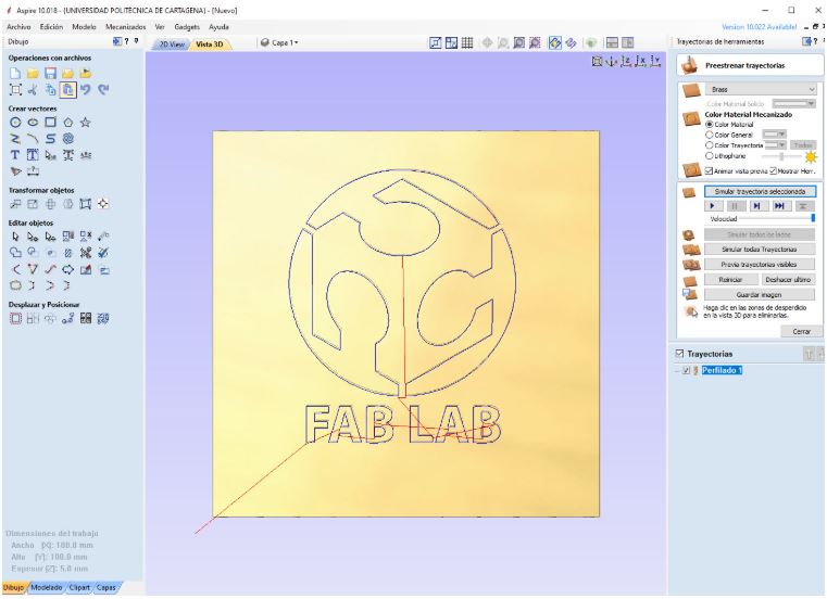
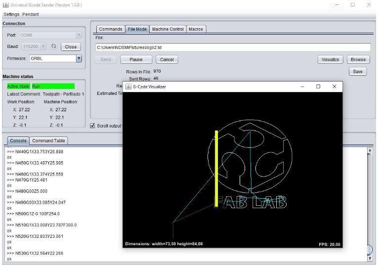
Finally we open this Gcode in Universal Gcode Sender and it works correctly.
18.7. Results
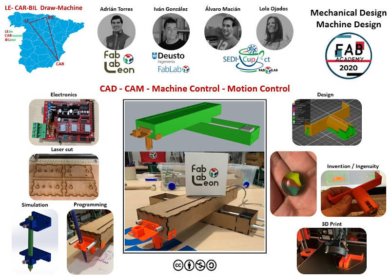
After all our work, I have designed the summary slide that will serve to show the results of our machine and I have compiled graphic information for the creation of the video that includes the work process followed from the initial idea to have a mechanical machine programmed and working ready, i this assignment, in a very short time.
We present:
LE-CAR-BIL DRAW MACHINE
Sumary slide
Video clip
18.8. Updates
When we started testing the machine, we realized that sometimes the machine was “lame”, did not rest well on the horizontal plane, and the tool part was raised.
So Adrián made by 3D printing another support with the marble equal to the one we were already using to put it at the end of the axis and this corrected the problem.
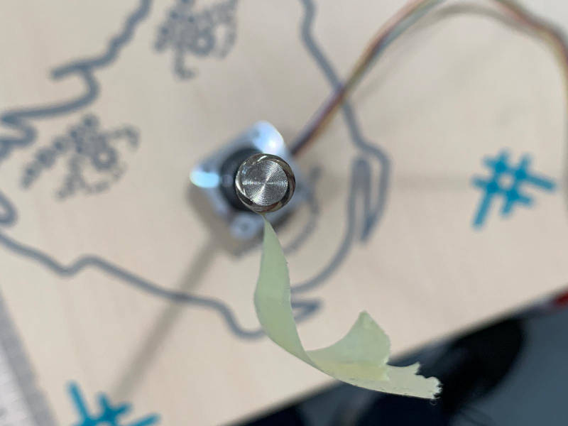
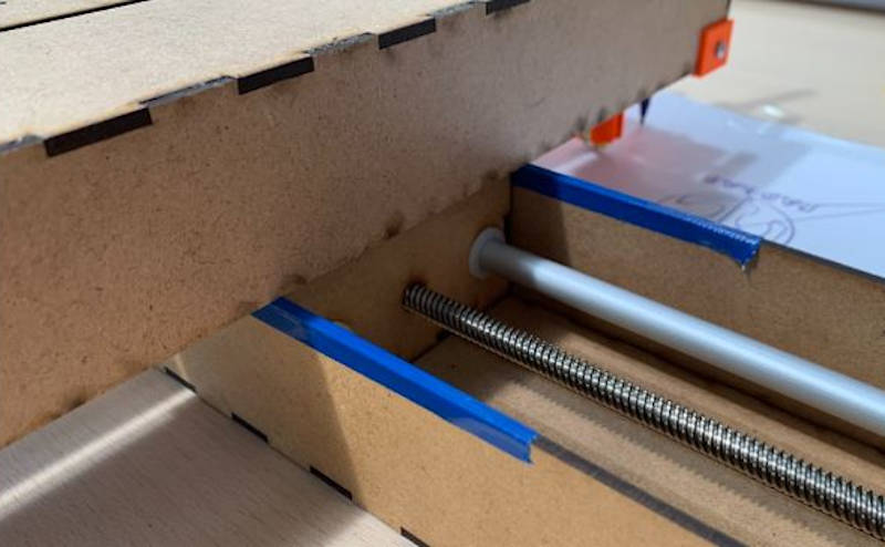
Another improvement introduced was to avoid the noise caused by the friction of the two Nadya modules.
For this, Adrián and Pablo had the idea of putting some vinyl or tape on the profile and saying goodbye to the noise. 😅
18.9.Possible improvements
If we had had more time, we were discussing that it would be good to improve the end effector.
- End effector improvement:
This could be done using some type of actuator like a rack and pinion to raise and lower the marker and thus avoid that in the transfer of the tool from one point to another these trajectories (which should be in the air) were drawn on the page.
- Tool type change:
Another thing you could try would be to use another type of tool to change the function of the machine. With the current marker (pencil, pen, marker …), the machine is capable of drawing what we program, it is a 2D drawing plotter.
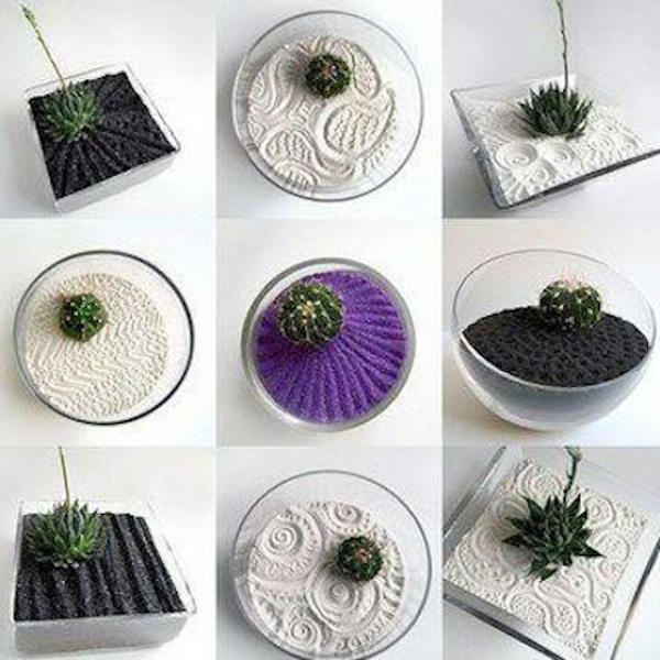
But if we change the marker for a ball like a marble, or a cylinder finished in a hemisphere, paths could be traced on sand, creating a beautiful Zen garden.
You could also put in place of a marker a punch that marks and cuts according to pressure (if we put the actuator or the rack pinion) extended mass of cookies, thus obtaining cutting forms and drawings on them.


As Pablo (our instructor at Fablab León) suggested, this punch could also be used on modeling clay.
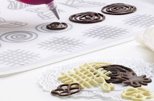
If instead of a punch we put a syringe and an actuator that gradually pushes its plunger, we can drop products such as jam, syrup or chocolate cream on sweets, cookies or cupcakes.

It shows that it is time to eat, most of the things that occur to me have to do with cooking and food… 😊