15. NETWORKING AND COMMUNICATIONS
I have done this assignment outside the corresponding week, in which in Spain we were in a state of confinement due to health alarm. I was also sick.
So I have done this task after I have finished and presented my final work, and therefore I have already created my own board that controls the security device that I have developed for my final project. And also input and output boards and my Helloboard.
The statement of this assignment is as follows:
Individual assignment:
Design, build, and connect wired or wireless node(s) with network or bus addresses.
Group assignment: Go to Link
Send a message between two projects.
In this case, unlike other weeks, I have developed individual work before group work, which I usually do with my partner Álvaro.
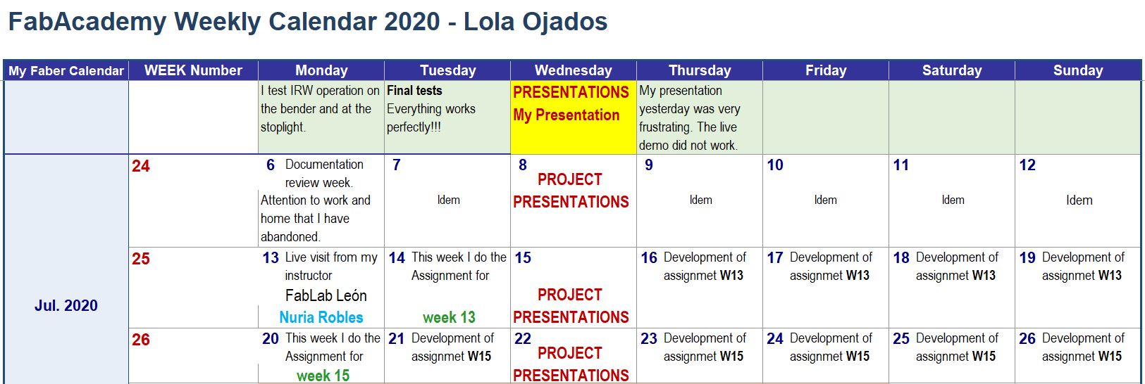
This is the schedule that I have followed this week:
15.1. INDIVIDUAL ASSIGNMENT
I am going to test the I2C connection to communicate 2 boards one with ATMEGA328 and other with Attiny44.
I use my IRW control board with ATMEGA328 microprocessor and my HelloBoard done in the week 7 assignment with ATtiny44 microprocessor.
For communication between both boards, I take advantage of the fact that on the ATMEGA328 microprocessor IRW control board I already have an I2C port that I use to connect to the sensors (which have their different boards where the sensors are located, which although they include their own microprocessor do not would serve for this work).
15.1.1. I2C communication protocol information
In this section, I explain roughly what the I2C communication bus consists of.
Before doing this assignment, after using the I2C communication protocol to connect the infrared sensor boards of my final project in series with the electronic control board of my device, I look for information about this protocol to explain its operation and to be able to enhance communication in this assignment also between this control board, the serial sensors and Helloboard.
I find a useful link on this Instructables page where there is information about what I’m looking for.
I2C (Inter-Integrated Circuit Bus), also commonly known as TWI (Two Wire Interface), is a two-wire synchronous serial bus cable.
I2C (Inter-Integrated Circuit Bus), also commonly known as TWI (Two Wire Interface), is a two-wire synchronous serial bus cable.
• Use two cables. SDA (serial data) and SCL (serial clock). Each line has a pull-up resistance between the line and the positive rail. A good pull-up resistor is 1-10K ohms.
• It is a synchronous communication: this means that the data transfer is synchronized through a clock signal, generated by the master, which is present in all the connected devices.
• Serial: Serial transferred data means that a single bit is transferred at a time over a single cable.
• Bus: A bus is a system that allows many devices to communicate with each other through a single set of cables. They use an addressing system, in which each device has a unique address.
15.1.2. I2C communication protocol operation
There must be a master and a slave, and each one fulfills a purpose.
A master can request to send or receive data from a slave. During a send, the master writes data to the bus and the slave reads the data from the bus and stores it in its memory. During a reception, the master reads the bus for the data sent by the slave. In both situations, the master provides the clock signal in SCK.
15.1.3. I2C libraries
In this section, the necessary libraries for programming the I2C communication between the two boards are exposed.
I know the library Wire.h to program the I2C communication between devices, since I have only tried this communication programming to program with arduinos, where it is valid.
But, in the current case, I need to communicate an ATtiny-44 (my Helloborad) with an ATMEGA-328 (electronic control board of my IRW security device) and this library is not appropriate.
After searching the Internet, I find these libraries for I2C communication with ATttiny microprocessors:
• TinyWireM.h Library for the Master device. Specific link & Original link.
• TinyWireS.h Library for the Slave device. Specific link & Original link.
So I have run the tests using Wire.h and TinyWireS.h, to use the ATMEGA-328 board as a master and the Helloboard as a slave.
15.1.4. I2C communication between my two boards
These are my two plates to communicate:
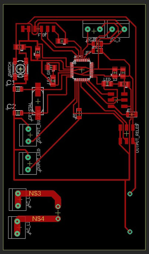
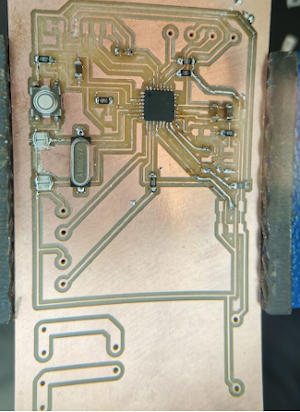
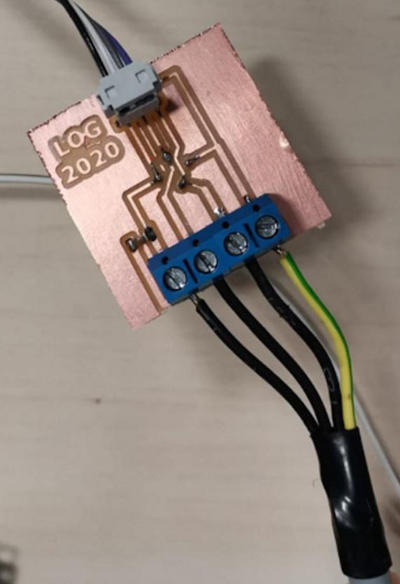
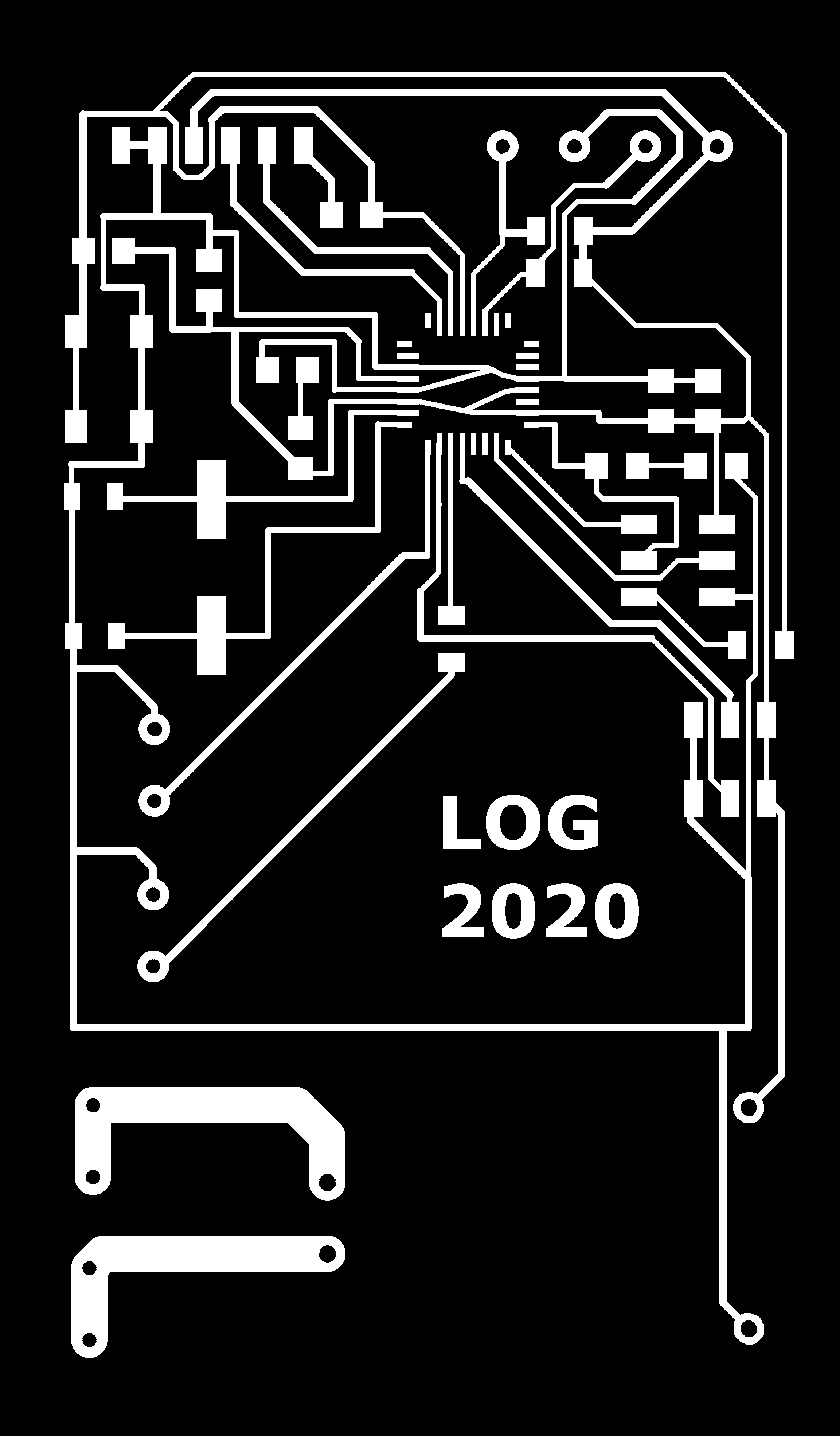
The electronic IRW control board with ATMEGA328 microprocessor:
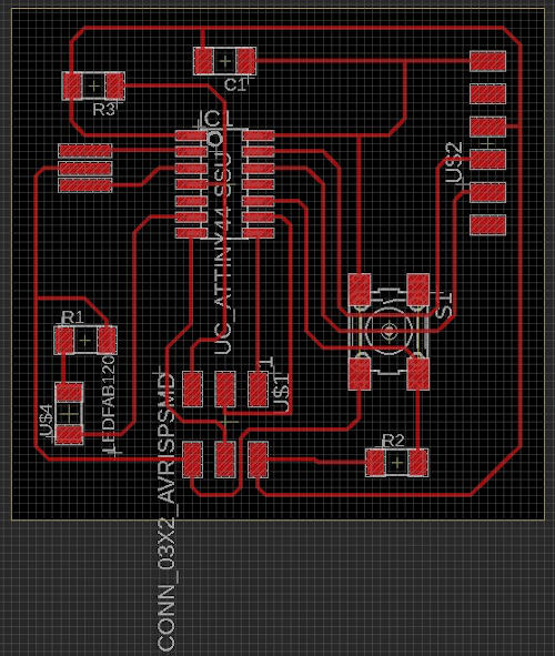
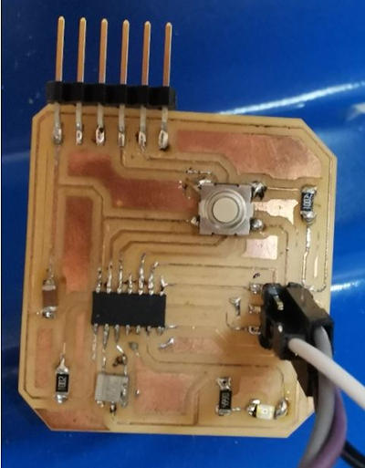
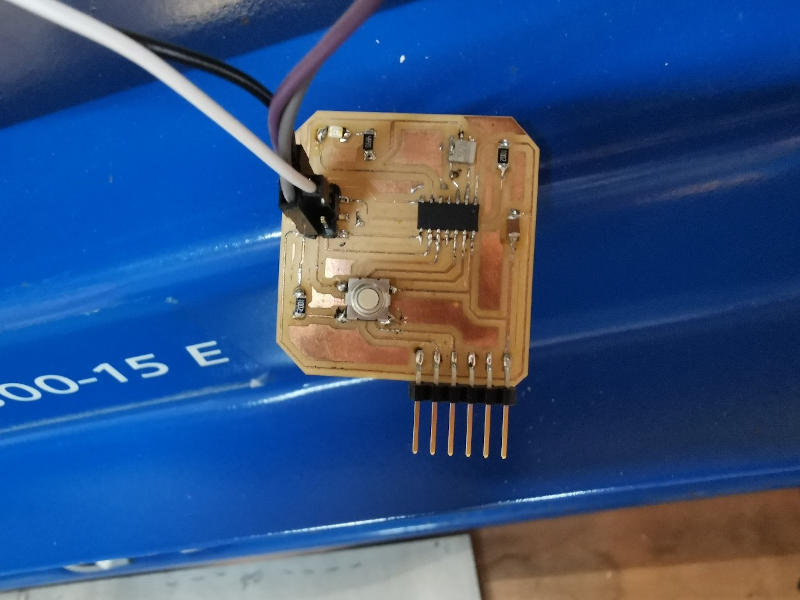
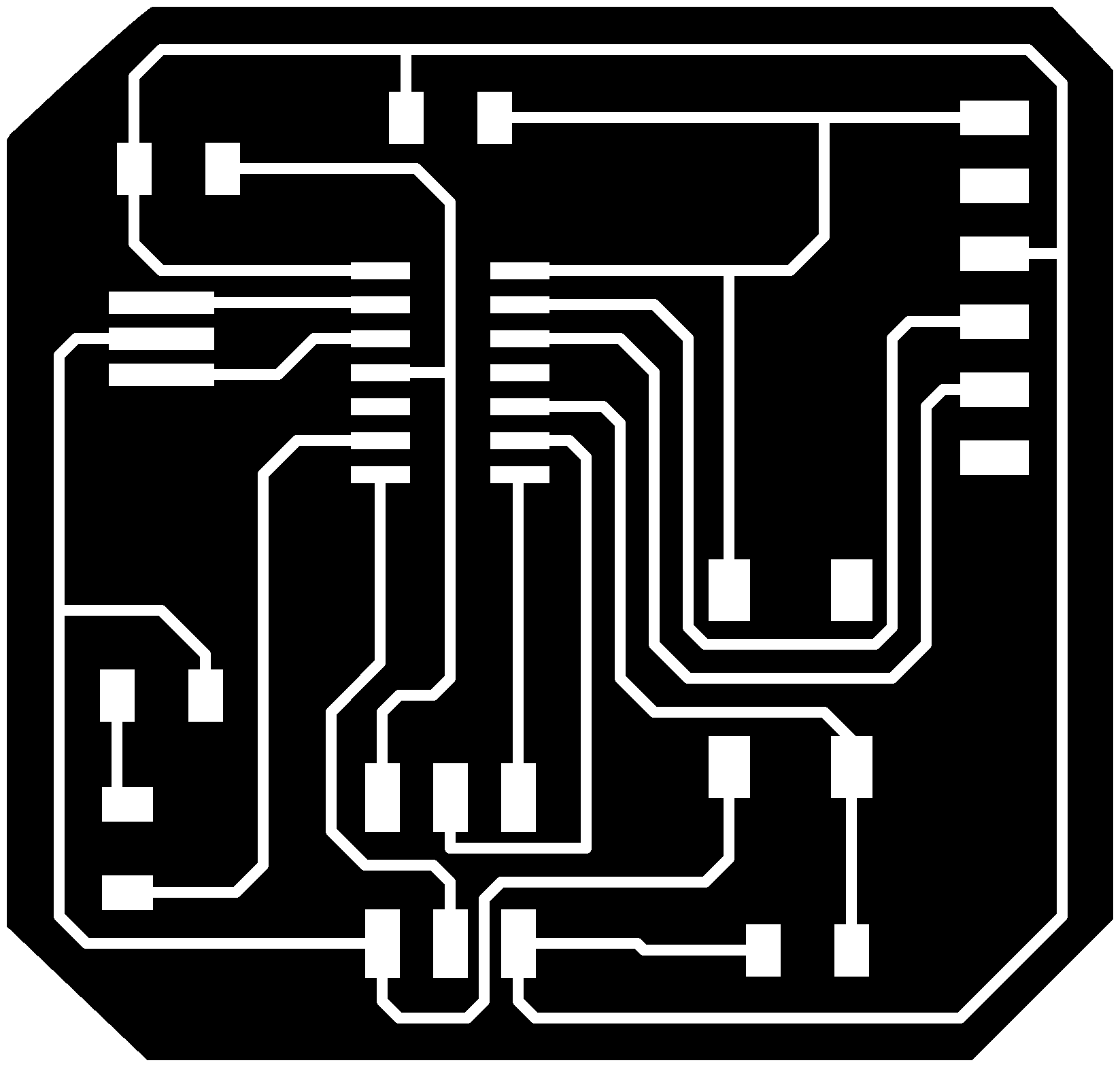
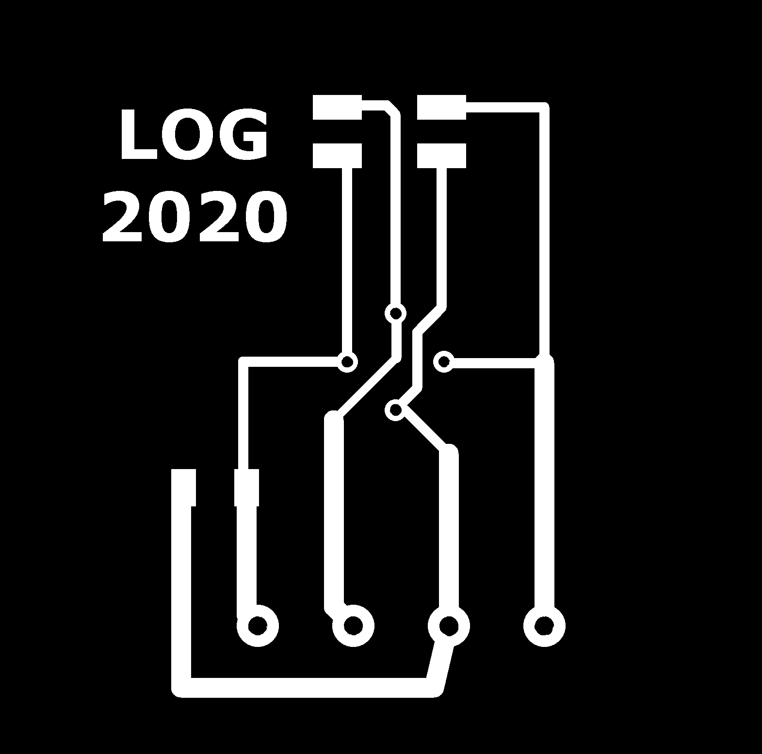
The Helloboard with ATtiny-44 microprocessor:
First I study the pins to make connections.
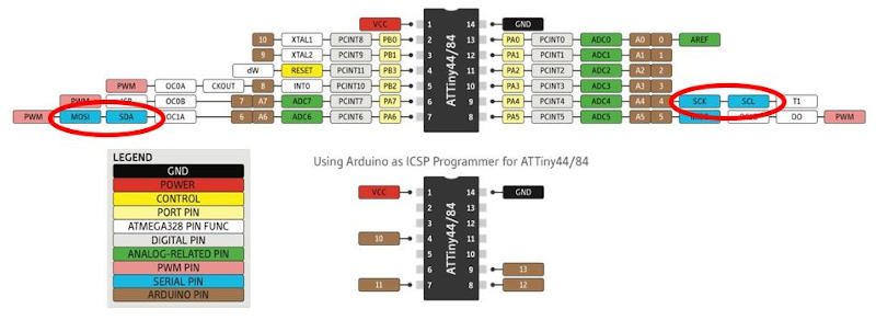
In the ATtiny 44 pin distribution I check that pin nº 9 is used to connect bothSCK (ISP connector) and SCL (I2C connector).
And pin nº 7 serves to connect both MOSI (ISP connector) and SDA (I2C connector).
So I can connect the two boards since I have both (VCC, GND, MOSI / SDA, SCK / SCL).
ATMEGA-328
ISP connector of my board (pins)
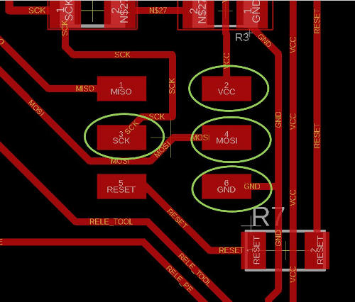
ATtiny-44
Connector of my Helloboard (pins)
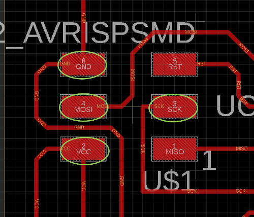
Diagram of the first level of connections between the LOG-ATMEGA-328 control board and my HelloBoard ATtiny44:
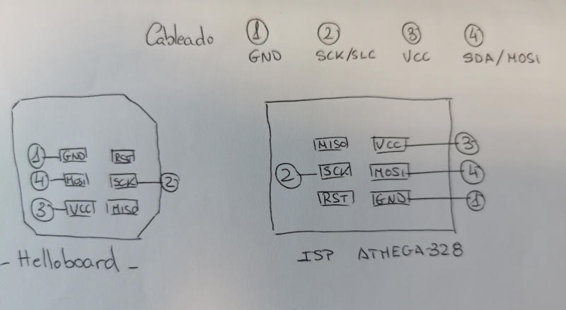
Pin connection between both boards:
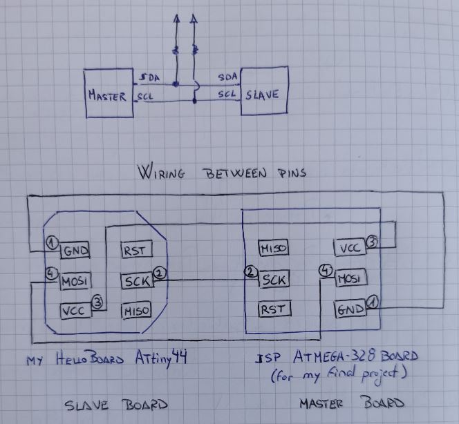
Complete diagram of the network of connected boards:
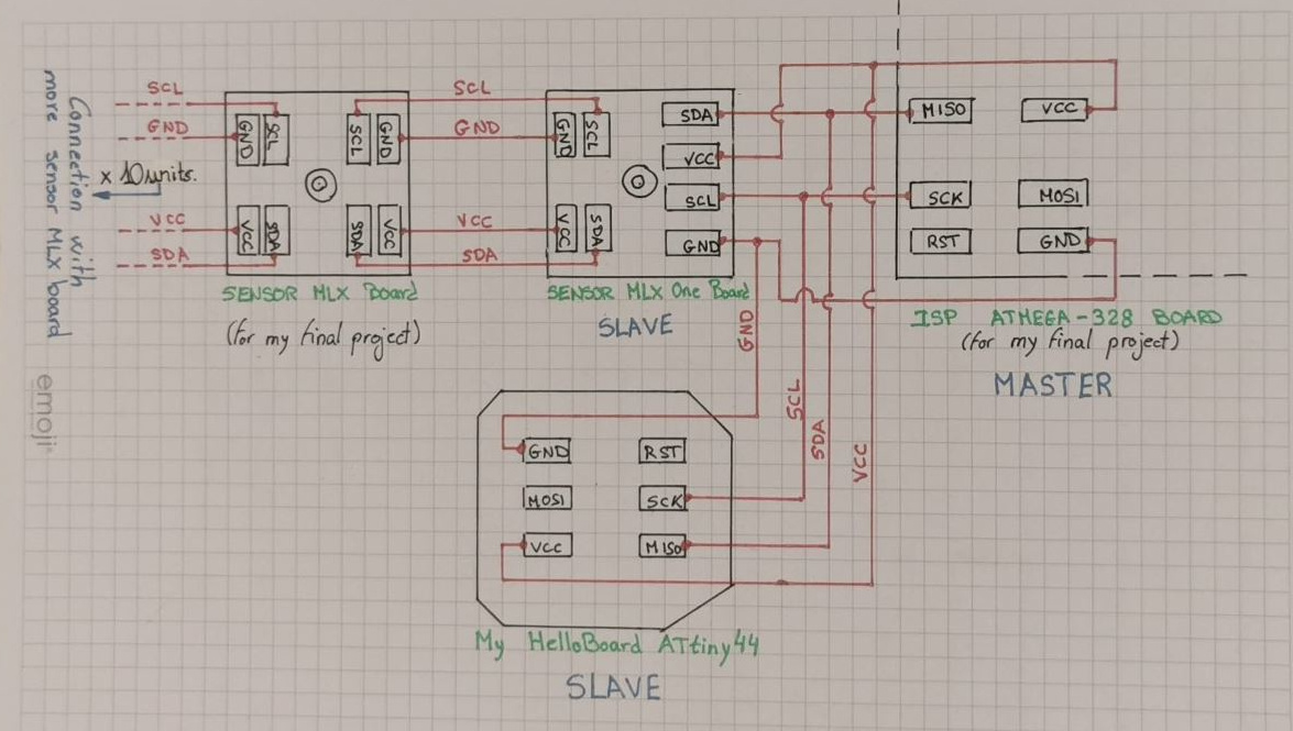
This diagram shows all the boards connected to the network, the LOG-ATMEGA-328 control board is connected to the HelloBoard ATtiny44 through the SENSOR MLX One Board created by me for my final project, which in turn is connected in series to 10 other boards called SENSOR MLX Board, all of them have an infrared sensor capable of measuring the temperature of the body that is approaching and entering its reading field.
Communication is I2C between all the boards, the two boards that contain a microprocessor created by me throughout fabacademy and for my final project, which also communicate in series via I2C with the sensor boards that are considered SHIELD type where each The sensor has its own internal microcontroller.
15.1.5. Physical wiring of my boards
To facilitate the actual physical connection between the corresponding pins of one board and another, since my board is inside the electronic control box of the security device, I connect the HelloBoard on the I2C bus via the initial board of the chain of sensors connected in series.
This is my ATMEGA-328 Control Board:
This is my Helloboard:
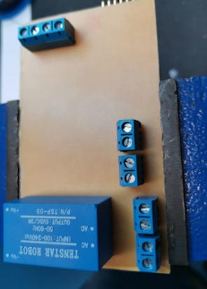
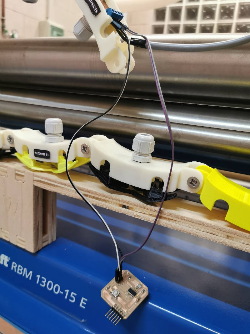
This is the initial sensor board, that is connected to the control board that is located inside a box that interconnects all the electronic components of the device that I have designed in my final project. (for more information about this board and the box that integrates the electronic control elements of the device, you can consult the link where the development of my final project is explained):
This board is connected to the ATMEGA-328 control board, which is inside the control box and in order not to disassemble the box and the IRW device, I have connected my Helloboard to this initial sensor board instead of directly to the ATMEGA.
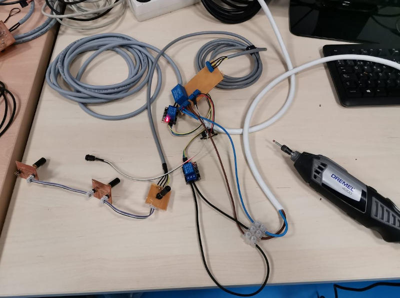
This image shows the connection of the control board with this infrared sensor board and with the rest of the sensor boards that are part of the IRW device of my final project, connected in series.
These are the connections of the Helloboard pins:
These are the initial sensor board pin connections:
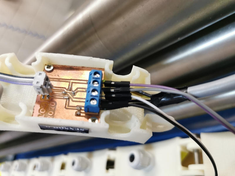
Both boards are connected like this:
15.1.6. Communication programming between boards
For the development of this assignment I am going to communicate through I2C the two described boards so that my control board with ATMEGA 328 microprocessor is the Master board and the Hello Board with the ATtiny 44 is my Slave board.
To do this, I impose a condition on my programming, so that what I want to do works, which would be the premise that I define below.
PREMISE OF MY PROGRAMMING:
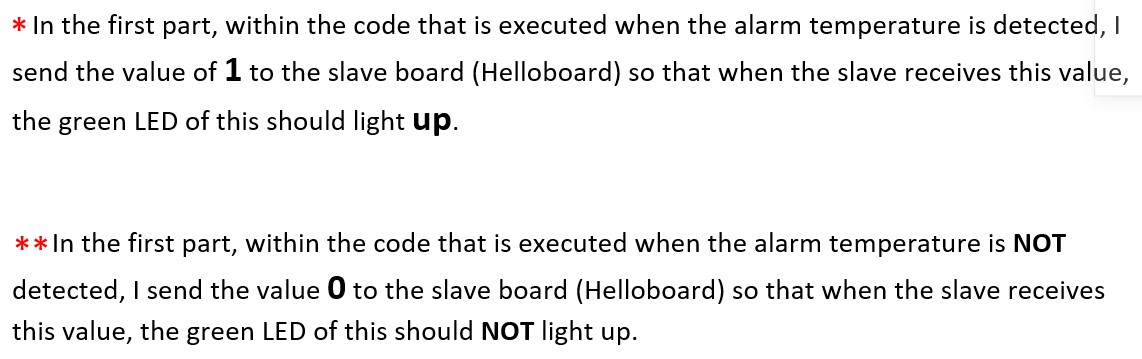
When the master board detects the temperature measured by the sensors and it reaches the alarm value at which the led, the buzzer and the machine stop relay must be activated, it will send a signal to the slave board to turn on the led that it contains.
To program the master board I use the wire.h library for I2C communication
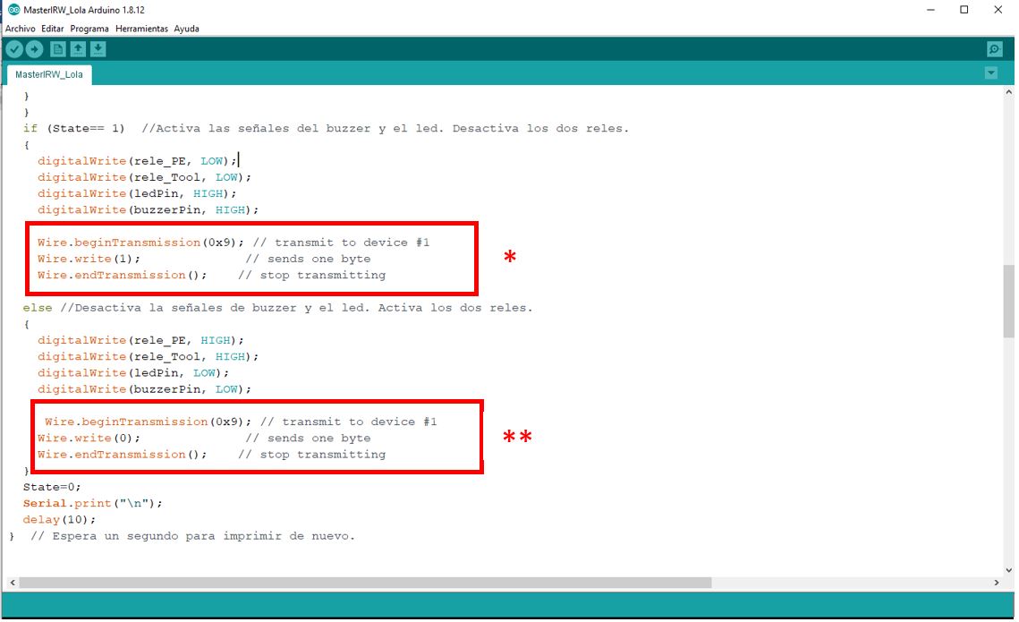
The two parts of the code framed in red, are the ones that I have included in the programming I did for my final work in which the sensors communicated with the control board and I managed to make an emergency stop.
To program the slave board I use the TinyWireS.h library for I2C communication
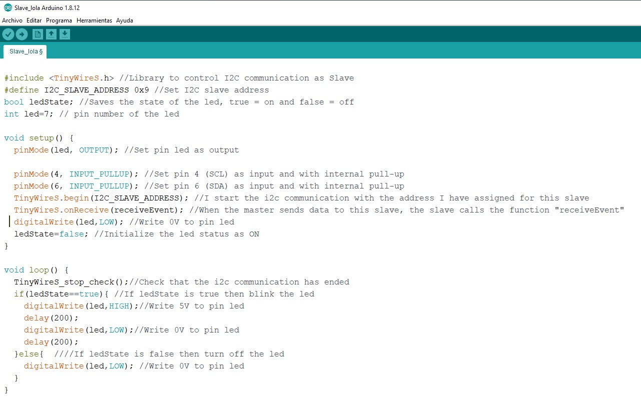
In the comments of the code it is indicated step by step what each line of programming does.
With this I will be able to communicate my boards and make what I proposed in my initial premise happen.
And this is the result that I have obtained.
I have managed to communicate my Helloboard and program it to perform an action (turn on its LED) when there is a risk of trapping in the machine tool in which I have implanted my IRW safety device.
15.1.7. Links to my Codes
15.1.7. Files corresponding to my boards
ATMEGA-328
- EAGLE file:
- Board PNG files:
HelloBoard
- EAGLE file:
- Board PNG files:
Sensor MLX One Board
- EAGLE file:
Sensor MLX One Board EAGLE_project
- Board PNG files:
Sensor MLX Board
- EAGLE file:
Sensor MLX Board EAGLE_project
- Board PNG files: