12. OUTPUT DEVICES
This week I worked on Week 12 assignment:
Again there are two different tasks to do individually and in groups.
Individual assignment:
Add an output device to a microcontroller board you’ve designed, and program it to do something.
Group assignment:
Measure the power consumption of an output device
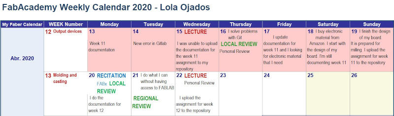
As every week, I continue to indicate in my weekly planning the tasks carried out in FabAcademy
We are still confined in alarm and cannot go to FABLAB yet.
I will try to do my best for this week’s assignment with the resources I have at home.
12.1. GROUP ASSIGNMENT
The Group Assignment page is at the following link.
The group assignments are done together by my colleague Álvaro and I from SEDI-CUp-ct FABLAB as remote students of Fablab León.
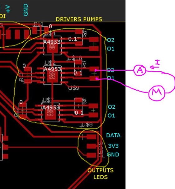
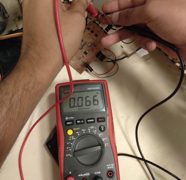
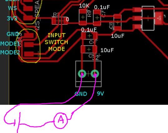
We are going to measure the consumption of my source.
First I measure the consumption of a pump. Ip = 0.066A
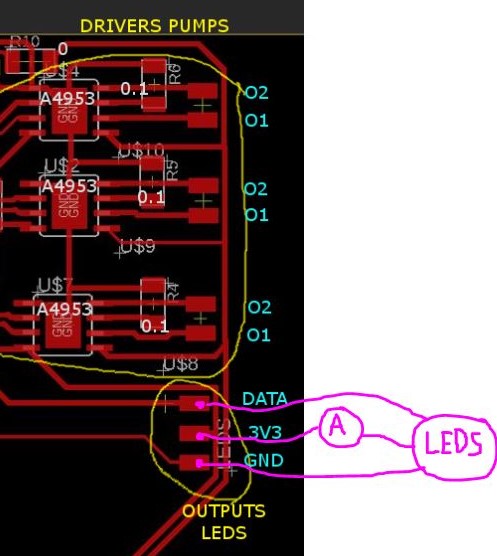
Then I measure the consumption of the 19 LEDs. Il = 0.05A
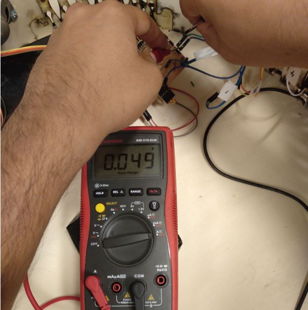
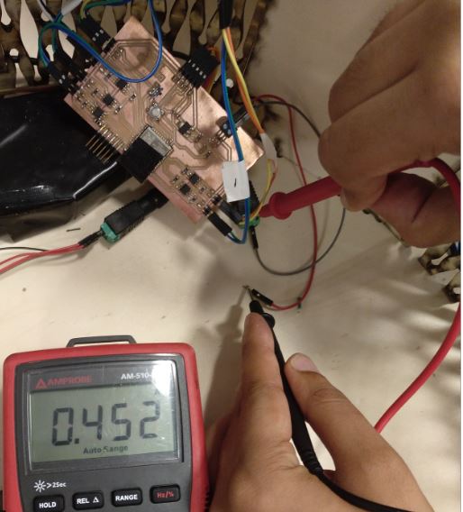
Finally the consumption of my board with the microphone, 5 pumps and 19 leds. It = 0.452A.
12.2. INDIVIDUAL ASSIGNMENT
12.2.1. Output Device board design
For the design of the electronic control system, the safety device that I am going to carry out as final work, I have designed in the assignment of “Input Devices” a board where I chose the microcontroller that seemed most appropriate to me and the different components that made up that board with input function.
In this assignment I am going to take that board as the starting design.
In last week’s assignment, I considered the needs of my final project, and I identified what would be the outputs that my electronic control system should be composed of.
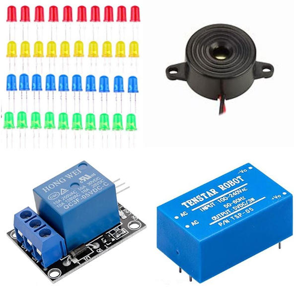
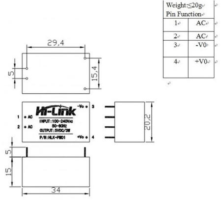
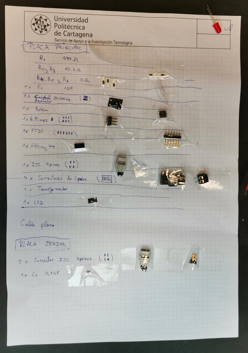
I will need a led and a buzzer to act as an alarm when a part of the human body comes dangerously close to the unsafe area of the machine and for the immediate stop, considered an emergency, of the machine in this critical situation, a relay will act.
I will also need a transformer.
These are the components therefore that I will have to incorporate into my control system.
On the board, I have to include the necessary transformer and connectors.
The first thing I have to do for it is about the input project in Eagle, create the components that I need to introduce and it does not exist in the libraries available in this program.
From Eagle, in bookstores I will put the transformer that I am missing:
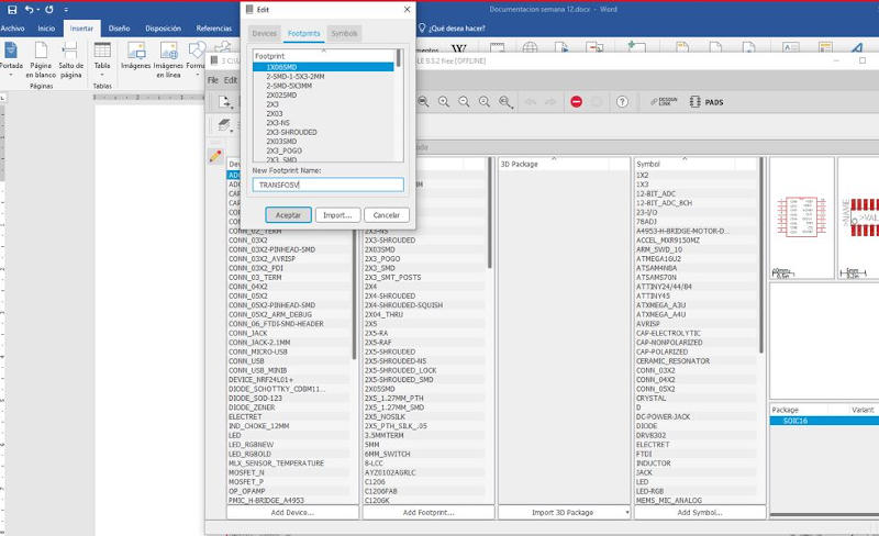
I accept the creation of the new element, transformer and I say yes to create a new footprint.
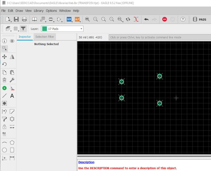
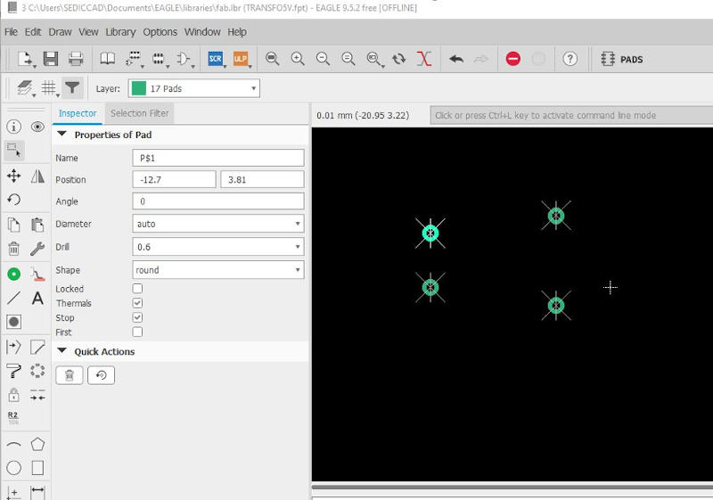
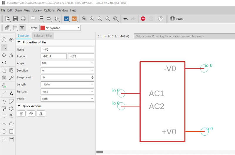
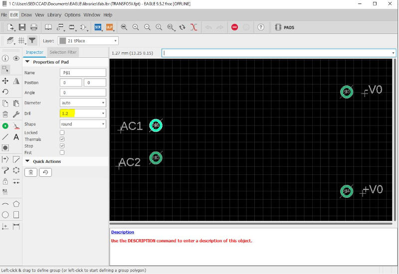
Now I shape the footprint, introducing the pins that I need to define the 5V transformer and to be able to solder them to the board.
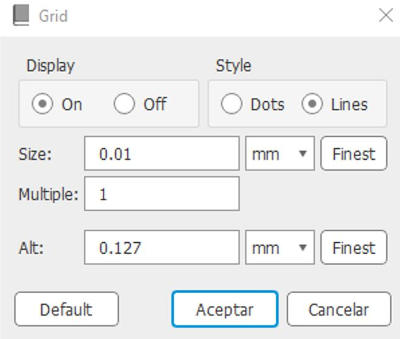
I change the units and the scale of the grid:
The positions and size of the hole diameter are shown (drill)
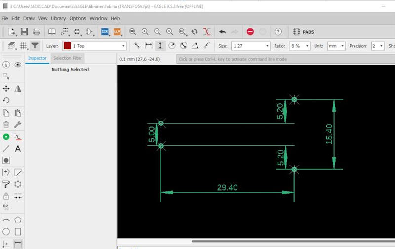
I put the position coordinates according to the scheme of this image:
I position and put the dimensions between the pins and the result is this:
I put texts and pass them to the Tnames layer
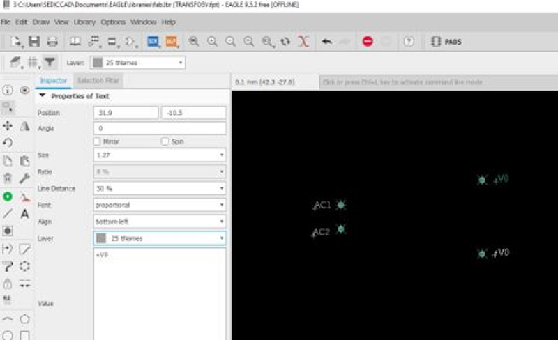
Now that I have the fingerprint, I save it and create the symbol that I name the same.
Now we need to create the device itself.
I add the previously created component, TRAFO 5V
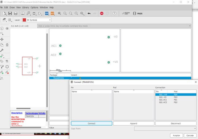
To connect it, I go to my schematic of my input board and add this component by searching the fab library, insert the new element, put cables and labels.
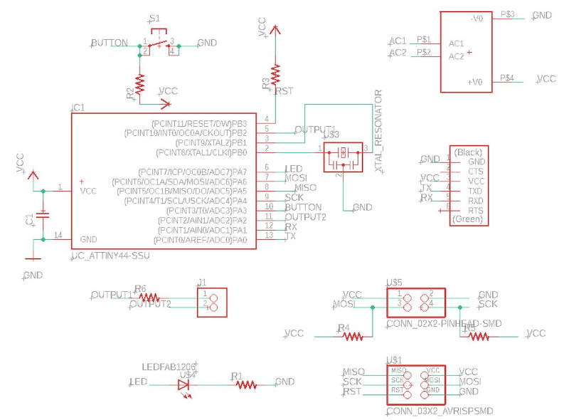
I go to the board design mode, and place these new elements on the board, the 5V transformer, and three 2-pin thermal connectors, to be able to connect the led, the buzzer and the relay.
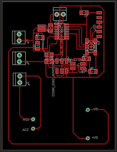
The scheme looks like this:
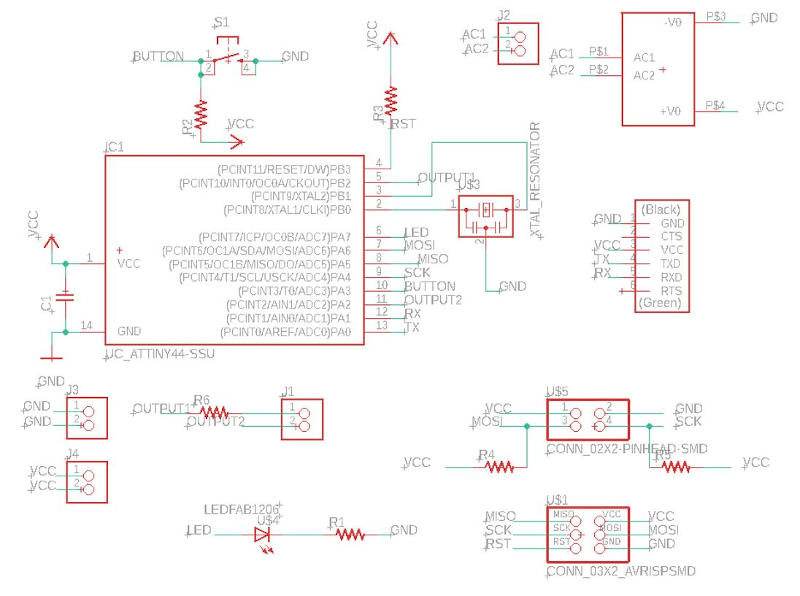
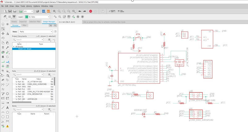
And the interface of the board is this:
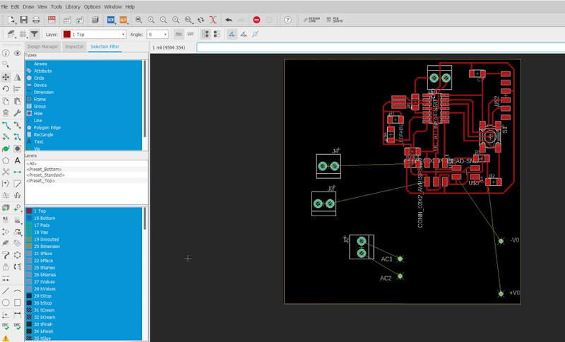
I have to expand the size of the board to fit the new components and connect them.
This is my new board, once configured, I check to detect possible errors.
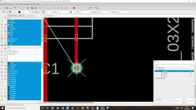
I detect an error in the diameter of the holes of the 5V transformer that I have created as a component to be able to have it available in the fab library and use it for the configuration of my board.
So I edit this new component created by me and modify the size of the holes where the connections of this transformer will go, except for the changes, I update and thus solve the errors that appeared when checking.
To update it, I delete the transformer from my schematic and re-import it. And now I have my correct 5V transformer.
In addition to this I have had to make more changes to my board.
After seeing the physical size of the transformer that I bought from Amazon and it has arrived late, I think I will need more space for it than I have left on my board, so I decide to reconfigure it and separate the transformer from the rest of the components a little since it is very big.
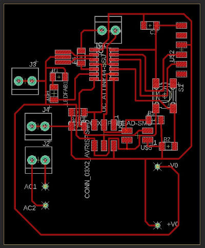
Here are the changes:
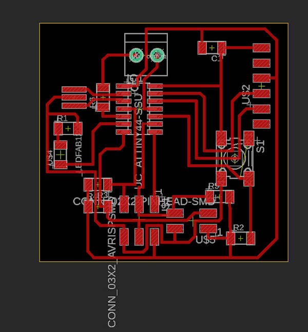
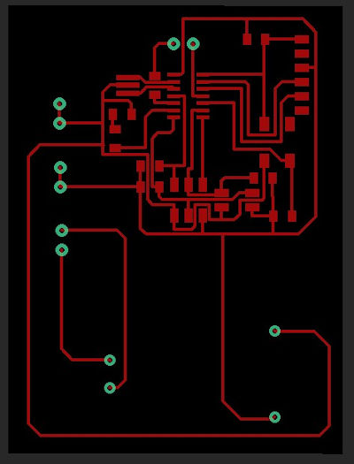
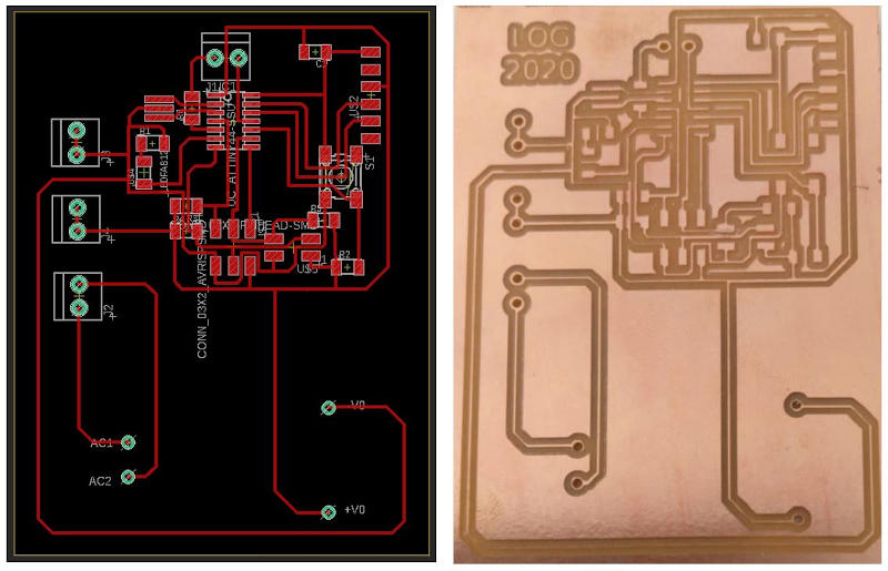
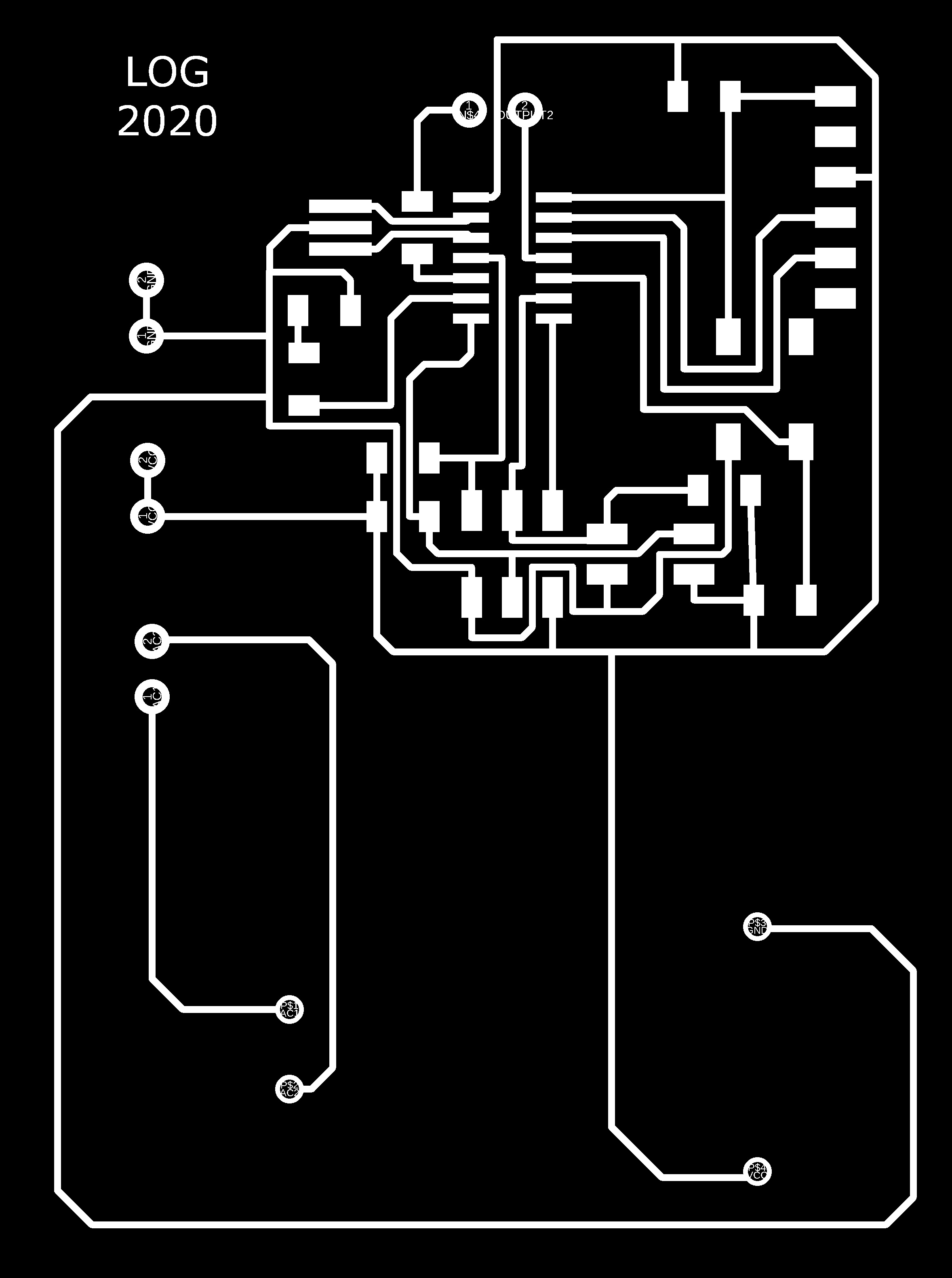
To prepare the board for milling, I must leave only the layers to be machined visible. And they are (Top, Pads and Vias).
After doing this, my board looks like this:
I export the file to type png image, in the assignment folder of this week with the name of Placa_Output_Lola.png

I open my image with Gimp.
I modify “canvas size”, use “flatten image”, put text: my initials + 2020. I export the image with the name of Placa_Output_Lola_01.png
It looks like this:
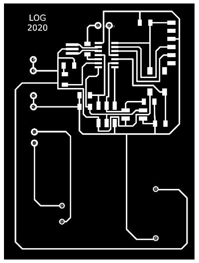
This is the board that I have to mill from my circuit recorder / cutter.
While I can not enter the FABLAB and I do not have access to the circuit milling machine that my colleague Álvaro has moved to his own house to be able to set it up, since it gave calibration problems, I will not be able to have my electronic board physically, so I am going to investigate any of these simulators. To simulate circuits:
Since the microprocessor on my board is ATtiny44 type and has 14 pins, it cannot be tested on all electronic circuit simulators.
My instructor Nuria recommends ATMEL Studio to me.
If I have time, I will test with these methods if my board works, if not, I will test it when I can have it printed.
12.2.2. Output Device board milling
Updating my assignment
As of May 18, I already have my printed board, the device’s control circuit board and the board where the infrared temperature sensor that acts as an input is integrated.
For this, even though we are still in confinement, I have to go to Álvaro’s house, who has brought the circuit milling machine home to be able to work on this assignment and things for the final project. We have taken precautions and respected security measures.
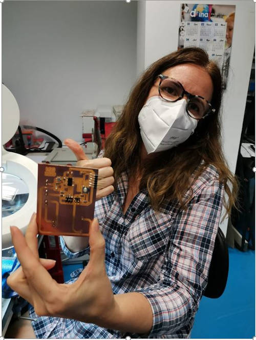
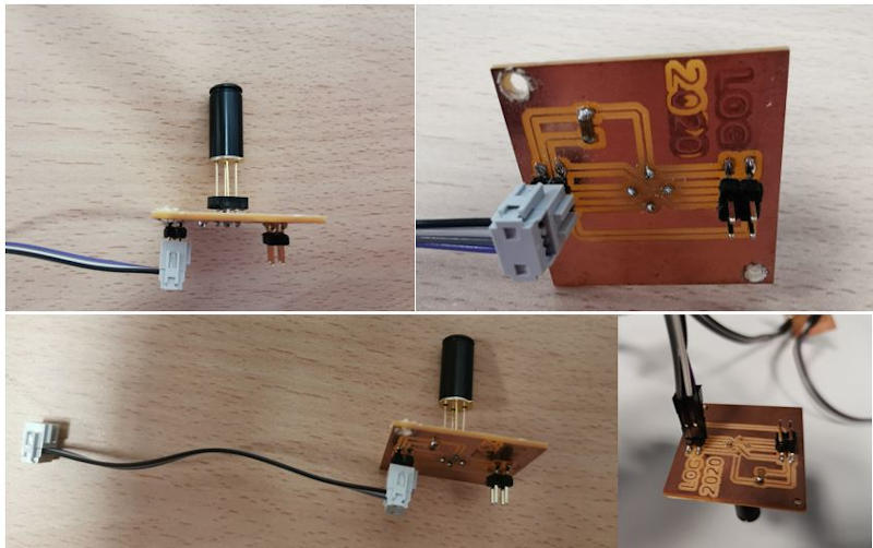
My board, once milled, are this:
So I’m getting ready to solder the components so I can test my board.
12.2.3. Output Device board welding
On June 4, I was able to go to the lab, which although it still has restricted access, upon request to enter the university’s occupational risk prevention service, I was able to enter.
After a good while soldering and checking connections …
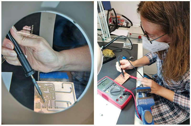
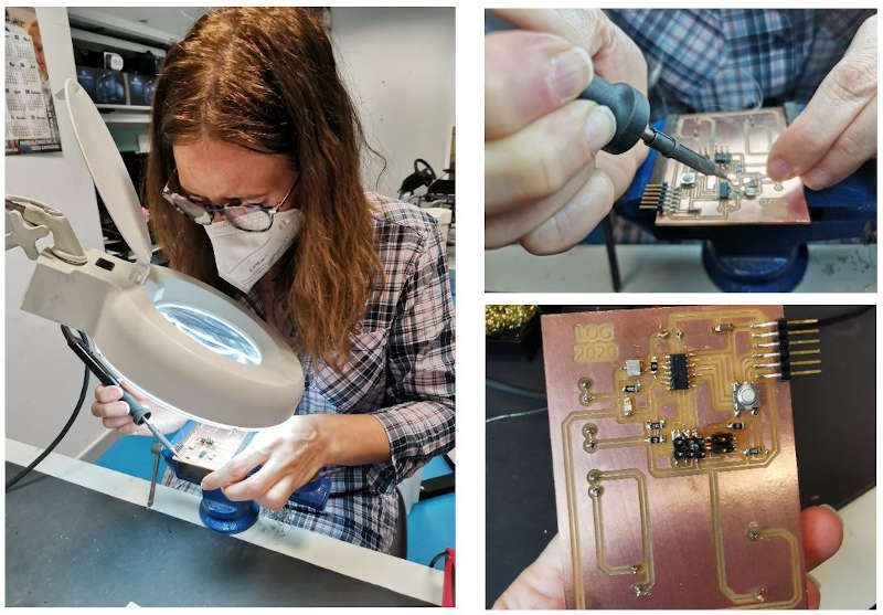
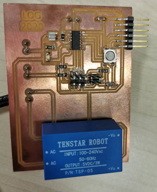
I finally finish welding my Output devices board.
When I try to make the connections and communications I realize that the transformer is soldered on the opposite side of the board, the poles cross, so I desolder and put the transformer well.
To check its operation, I took a first step and loaded a basic program to light an LED on the digital output and verified that the board works correctly.
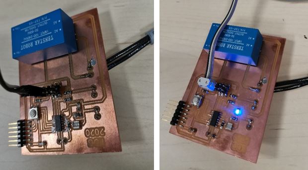
Up to here, I have achieved the proposed challenge for this assignmen!!
I have created my own OUTPUT board and it is capable of working and lighting an LED.
Here comes my big problem!!
For my Final Project.
I want to program the reading of the sensors and their on-screen display in real time. The programming does not fit in the memory of this microprocessor. I have been testing.
So I decide to change it to an ATtiny84 for the final control board of the final project and I will also make the connector tracks wider, especially for the power cable and the different outputs, which is quite thick and loses the connection.
I decide this microprocessor because it has the same pinout, I check it on its datasheet.
But, another problem!!
I do not have this microcontroller in my Fablab and if I order it it would take a long time for its supply to arrive.
In Spain, in my region it is said: “my joy in a well” or “if I go to the sea, it dries up”.
Which is something like, “my frustration is infinite”
Well, I recover and look for another solution. So I have to try another microcontroller, this will mean making more changes on the board than I originally thought would have to be done with the change from ATtiny44 to ATtiny84, but it is what there is.
I test with the ATtiny 1614 and make changes to the connections. I test the schedule, and…
Still, I can’t get good communication with I2C, nor do I get the programming to work well.
Here in this assignment, at least I prove that my board in the current conditions works and is capable of reading from the input board and giving command to a relay and / or a buzzer + a led and that each one fulfills a function under certain conditions. determined and fixed in the programming.
And for my Final Project:
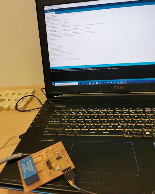
I try connecting my Input board and programming with Arduino and it works.
So finally, I decide that for my final project I am going to use the same microcontroller that carries the Arduino 1 board, with which communication and programming is somewhat more familiar to me.
So I start to design my board from the SATSHAKIT board
I will use the ATMega 328P microcontroller.
But this is “another story” told in the Final Project Development section of this Repository.
12.2.4. Files to download for this assignment
- EAGLE file:
- Board PNG files: