4. COMPUTER-CONTROLLED CUTTING
This week I made a group assignment in which my partner Álvaro Macián and me, from Sedicupt-Fablab in Cartagena, have characterized the laser cutter according to the material to be cut with different thicknesses. We have calculated the kerf of the machine.
In my individual assignment, I have made a design that I have vectorized and cut on the vinyl cutter. I have also created a parametric design that I cut on the laser cutter.
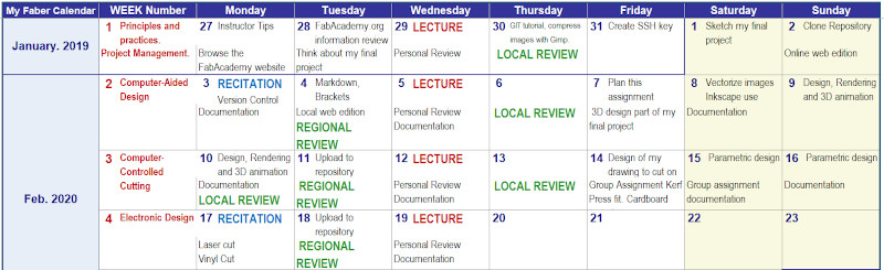
I have continued using my weekly planning in which I have updated my activity in FabAcademy
This has been my work sequence during this third week:
14/02/2020 I started planning the task of week 03, I designed the drawing of what I want to cut on vinyl and I’ve been doing my Group Assignment Kerf / Pressfit. Cardboard tested…
15/03/2020 I make my parametric design
16/02/2020 I make the cardboard laser cut of my parametric design
17/02/2020 I work on the documentation of my assignment and my extra-assignment
4.A. GROUP ASSIGNMENT
In my repository in each week in which a group assingment must be carried out, I include the documentation of the work done, but also the group work can be accessed on the Fablab website of which I am a remote student.
This is the link to access the space of group assignment from FABLAB León.
Now I start with the documentation of what I have done this week.
Characterize our lasercutter’s focus, power, speed, rate, kerf, and joint clearance
This group assignment was done by my partner Álvaro Macián and I together from our local node in Sedicup-Fablab, we are remote students of the Fablab León node.
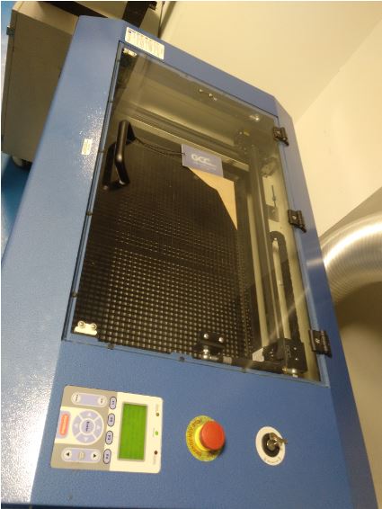
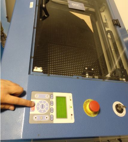
4.A.1. Identification of our laser cutter:
GCC LaserPro
Mercury III
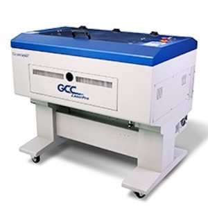
4.A.2. Mercury III description
Mercury III LaserPro is built by GCC (Great Computer Company) of Taiwan, making it the first laser to be imported from that part of the world.
Although the machine was assembled overseas, many of the most critical components were actually made in the US. Not only was the laser tube itself American made by Synrad™, the largest volume manufacturer of CO2 laser tubes in the world, motors and some of the electronics are also American-made.
Principles of a CO2 Laser:
LASER is the acronym for Light Amplification by Stimulated Emission of Radiation. A CO2 laser works by electrically stimulating the molecules within a carbon dioxide gas mixture. When focused through a lens, this highly-intense, invisible beam will vaporize many materials. Depending on the speed and intensity of the projected beam, a CO2 laser may be used to engrave or cut through a wide variety of materials.
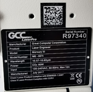
4.A.3. Specifications of the laser cutter:
The machine specification data is listed in the following table:
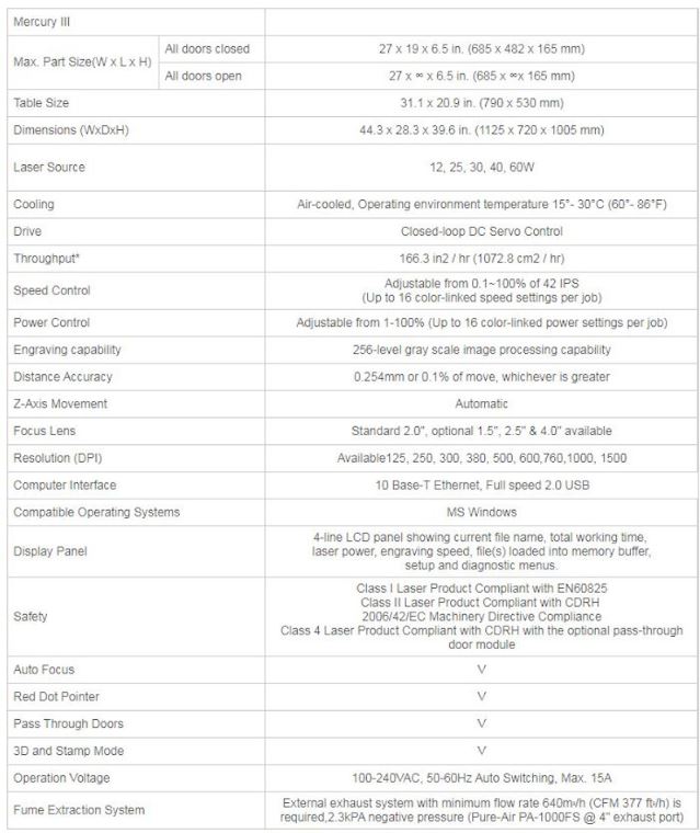
The laser source of our machine is 60W.
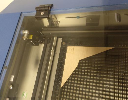
4.A.4. Focus of the Mercury III laser-cutter:
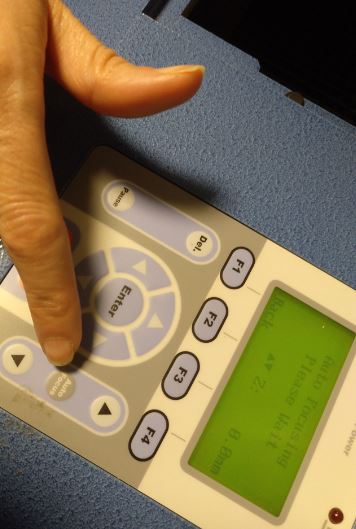
AUTO-FOCUS
Auto-focus is one feature that comes included with the Mercury III laser-cutter. Although there are people that prefer a manual focusing capability, manual focus is becoming a rare thing to find.
In the case of the GCC, there are research (1) that ensures GCC actually does focus correctly on almost every product—first time, every time.
(1) - informative articles
The mainly advantage of manual focus is when you want to roll something out of focus slightly.
This is doing often when engraving rounded or curved products. With the GCC, it easy to adjust the amount the lens was out of focus using the mathematical readout on the display. It is actually far more precise than focus the machine manually.
The GCC uses a different approach altogether to other laser-cutter. Instead of using an infrared light beam to find the thickness, the GCC uses a pressure-type switch mounted to the lens assembly. Because the lens assembly can be moved manually to any position on the table, even products with uneven surfaces can be easily registered accurately. For those, really tricky products, there is a simple drop-in tool that allows manual focusing or allows the engraver to double-check what the autofocus is doing.
One of the true advantages of the excellent focusing capability is how it increases the machine’s ability to cut thick materials. In cutting, it is important to be able to focus as much light energy as possible into the tiniest area. When comparing the machine’s cutting ability with the beam focused automatically and manually, the laser was capable of cutting much thicker materials when auto focused, even when I tried my very best to manually focus the light beam as precisely as I possibly could.
4.A.5. Power of our Mercuy III laser cutter:
The maximum power of the machine is 60W. (CO2 Laser source). As it appears in the specifications, the machine has POWER CONTROL adjustable from 1 - 100% (Up to 16 color-linked power settings per job). In the work of characterization of the machine, we have calculated the power and its ratio for the range of materials with which we usually work in our laboratory. Differentiating also in some of the cases between different thicknesses of the same material.
4.A.6. Speed of our Mercuy III laser cutter:
As it appears in the specifications, the maximum speed of the machine is 42IPS. (Inch Per Second). The Mercury III laser cutter machine has SPEED CONTROL adjustable from 1 - 100% (Up to 16 color-linked speed settings per job). In the work of characterization of the machine, we have calculated the speed and its ratio for the range of materials with which we usually work in our laboratory. Differentiating also in some of the cases between different thicknesses of the same material.
4.A.7. Rate of our Mercuy III laser cutter:
As we have indicated in sections 5 and 6, in the process of characterizing our laser cutter, we have calculated the speed rate and power rate for the range of materials and thicknesses used in our laboratory.
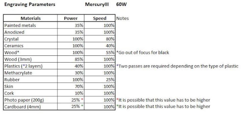
The starting information of the engraving and cutting parameters is in these two tables:
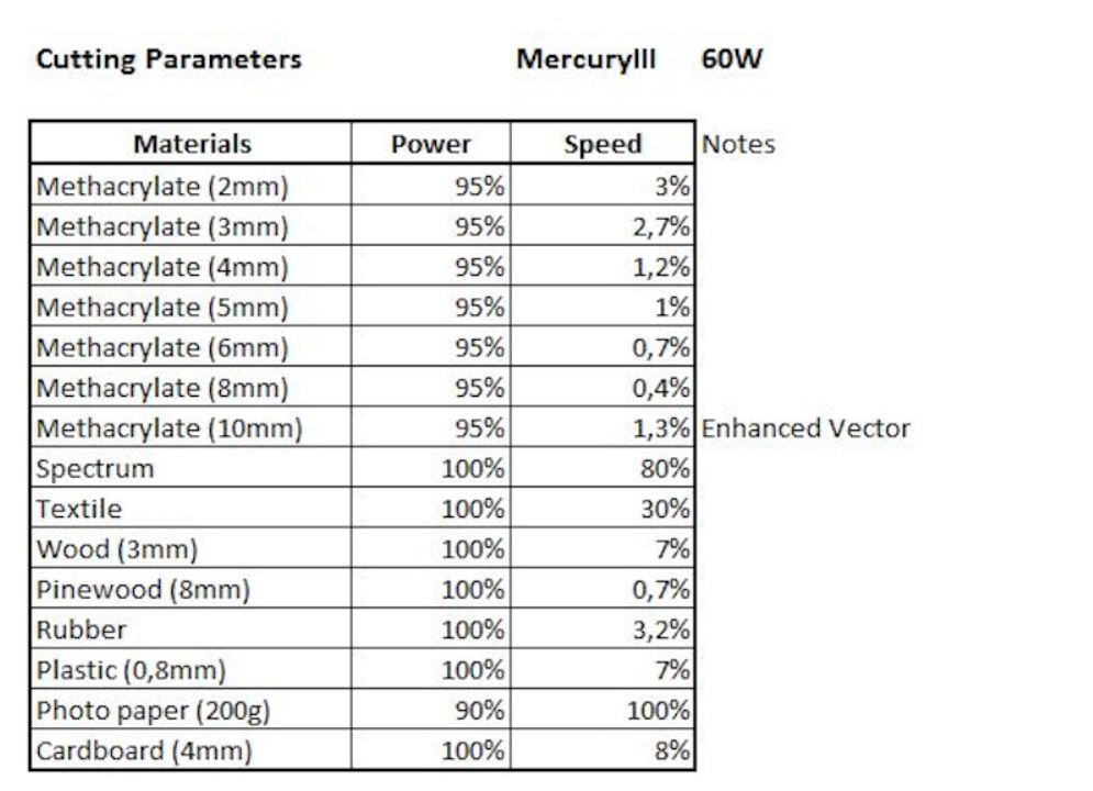
In the results section, we have detailed and updated all this information.
4.A.8. Kerf of our Mercuy III laser cutter:
For the calculation of the kerf, we must first know the distance “d”, which is calculated as the difference between the design dimension and the actual dimension of the cut object. Thus we know the thickness of the material that the laser burns by making the cut for each of the materials tested.
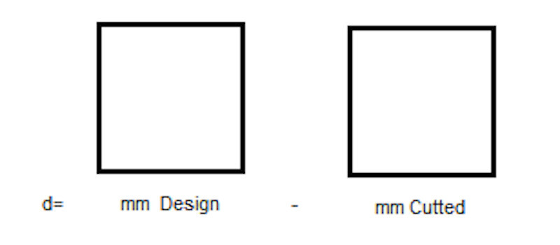
The kerf is the average value of that distance “d” and we have had it for the different materials we use.
Kerf = d / 2
4.A.9. Joint Clearance (offset of our parametric design) of our Mercuy III laser cutter:
The joint clearance is the distance between mating surfaces of a joint.
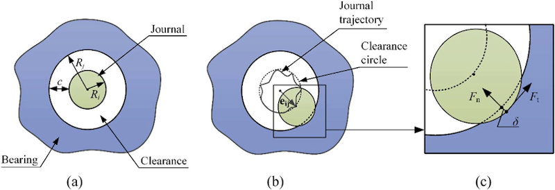
Model of clearance joint: (a) Nominal case, (b) Contact mode, and (c) Details of contact area.
4.A.10. Results
* The documentation of the results of this week’s group assignment has been written by my colleague Álvaro from SEDI-CUp-ct FABLAB. *
* This is the content of this part of this week’s assignment *
Depending on the material we cut or engrave with the laser cutter we will have to configure the speed and power parameters.
The manufacturer gives us general values for different materials.
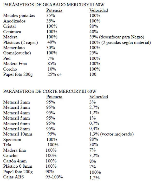
NOTE: DO NOT USE PVC, TOXIC VAPORS!
But these values may vary from one brand to another. Therefore, we have to check it for the materials we have. In addition we also get different kerf values. To test the values we have done cutting tests.
4.A.10.1. Velocity and power tests
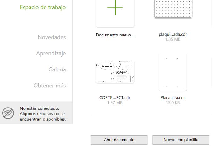
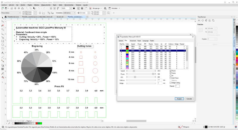
To use our machine we have to use the CorelDraw software, in which our machine is already predefined as a printer.
We will make a simple drawing to test the speed and cut parameters in our materials.
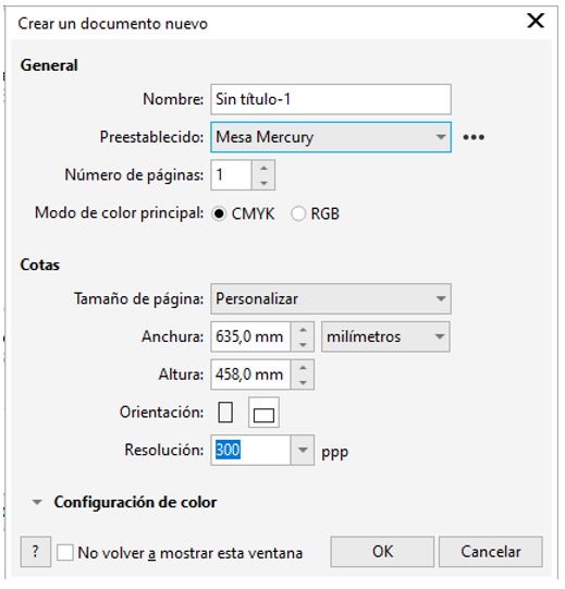
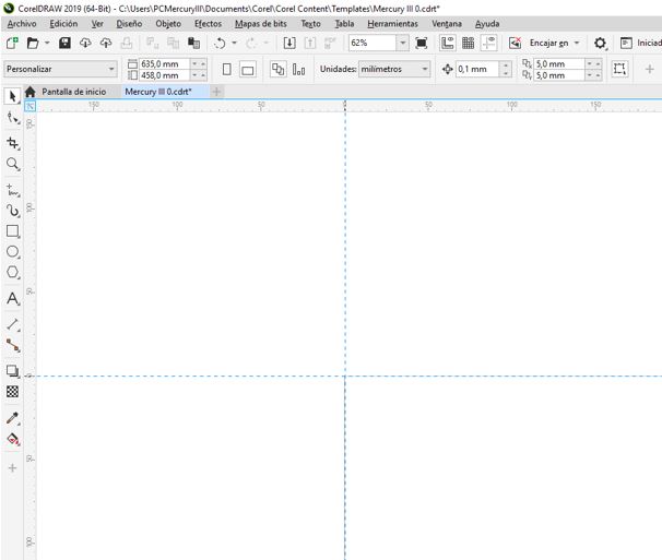
We open CorelDraw and create a new document.
A window opens to configure the worktable.
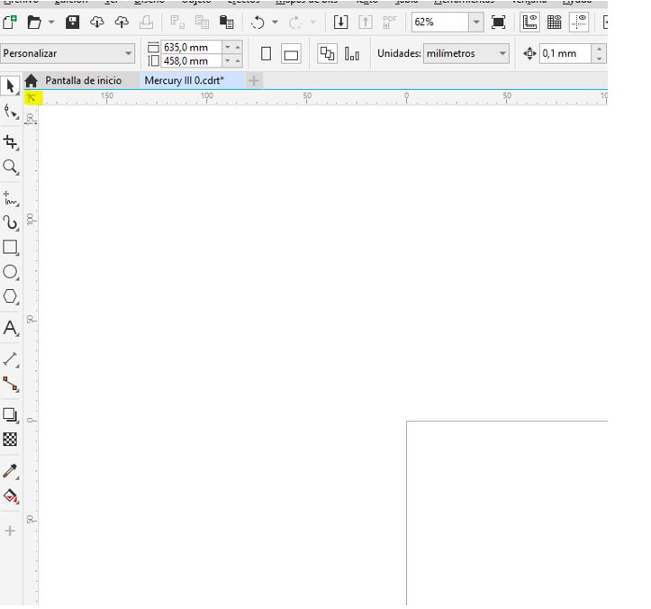
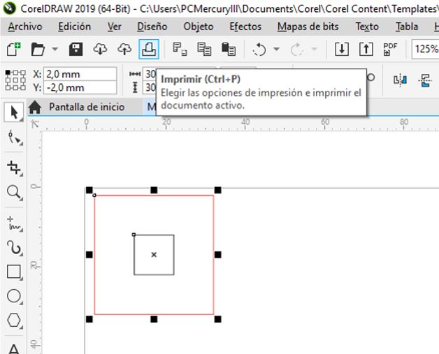
We click and drag on the next icon to set the zero of the template in the upper left corner to match the zero machine.
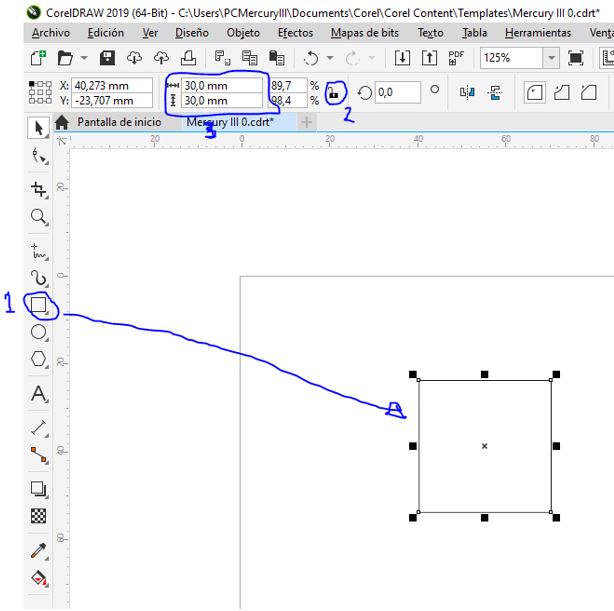
Now we select the rectangle tool and draw it in the template. I unlock the relationship between width and height, and introduce the measures that we want the rectangle to have.
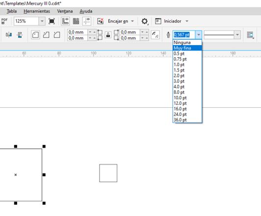
With the contour that we want to cut selected, we set the contour width. Less than 0.1mm means cut and higher engraving, so we select ‘Very Fine’ which is a value of less than 0.1mm assigned by this program for cutting.
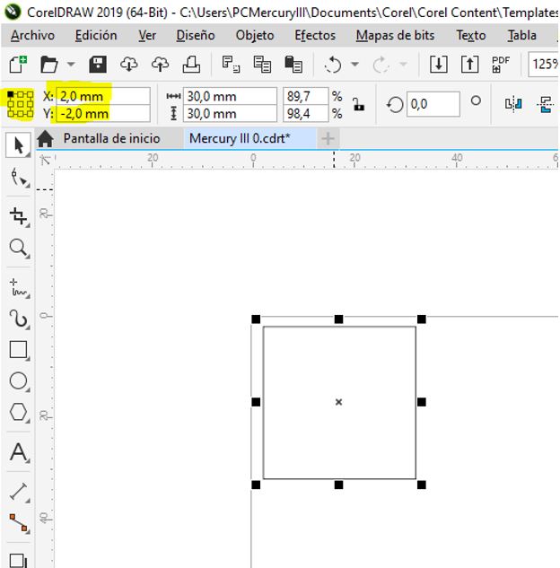
We align with respect to the zero machine. Select the object origin in the upper left corner and enter the coordinates. The minimum distance from zero of the machine at which we can place the object in x: 2mm y: 2mm when it comes to cutting (if it were recorded if we can put 0.0).
Now we configure the machine.
Depending on the color assigned to the contour or fill of the designed objects, the machine assigns an order of execution. And for each color we will assign the speed and power parameters. What determines whether it is a cutting or engraving operation are these two parameters and the material we are working with. The other determinant is the thickness of the line that we indicate in the software, if it is very thin, a cut or perimeter engraving will usually be made in the case where we give it more speed or less power.
We select the color of black contour for the square inside, and the red color for the square outside. This will be the first cut inside and then the outside.
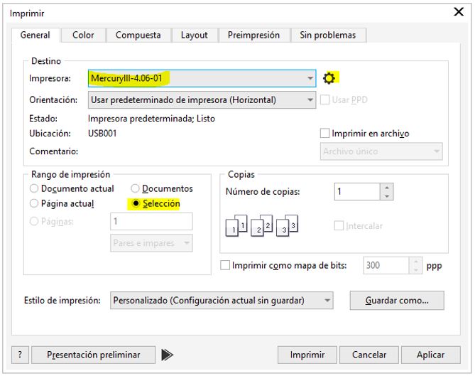
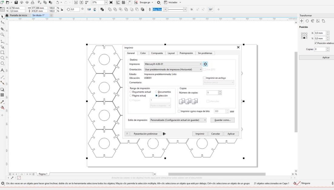
We select the printer. We mark the selection option and click on the gear to configure.
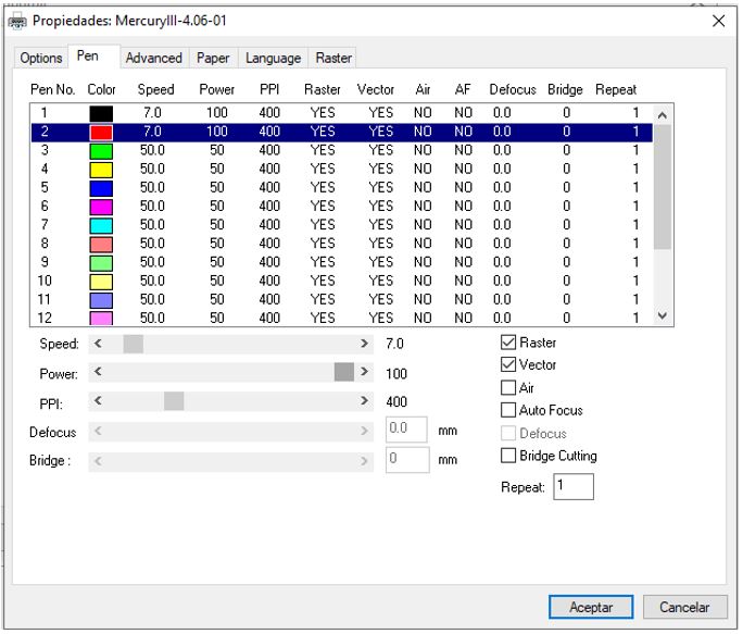
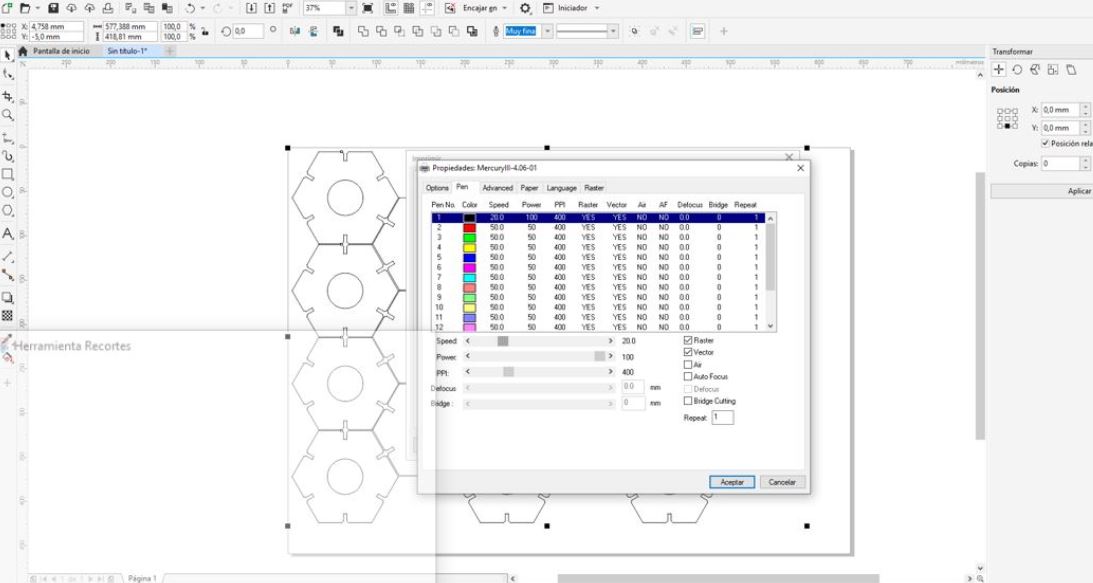
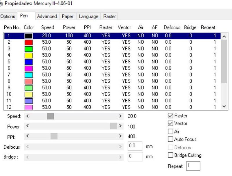
In this window, in the ‘Pen’ tab, we assign the parameters to each color.
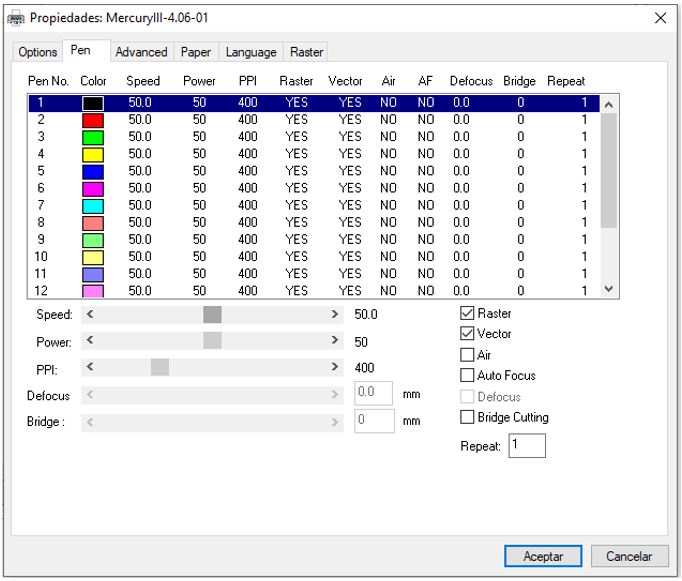
We assign the values for cutting in fine wood to black and red.
In this tab we can configure the machine to take as a reference the point that we indicate manually (moving the head with the buttons on the panel) to match the center of the object drawn using the ‘Center’ option. We will leave it with the default option, ‘Home’.
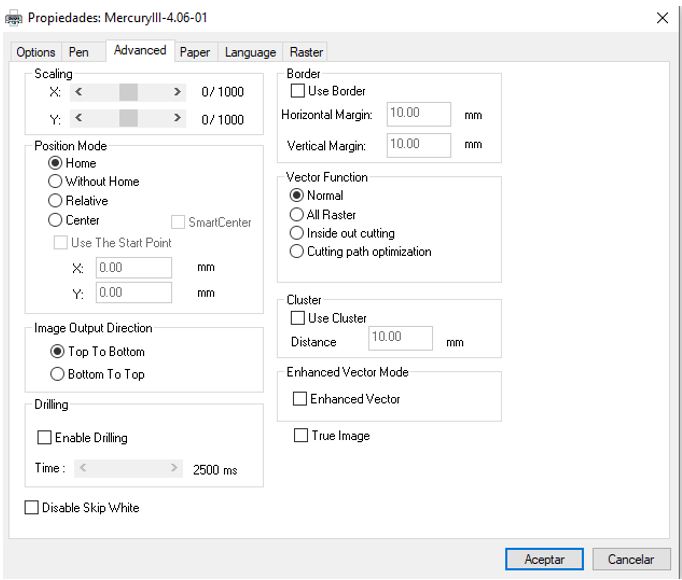
Ready! We accept and give you to print.
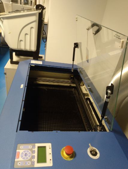
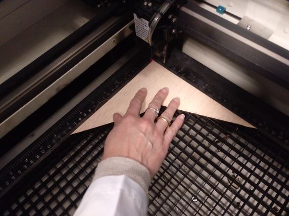
Now we are going to prepare the material that we are going to cut. We open the door and lower the bed to put the material without touching the head.
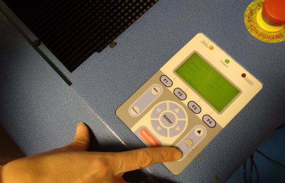
With the arrows we move the head to place it on top of the material and then we give ‘Auto Focus’.
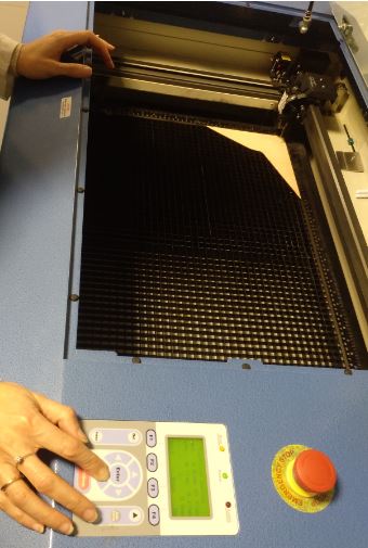
It is already calibrated.
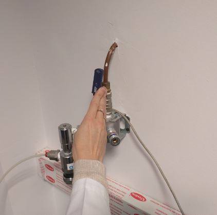
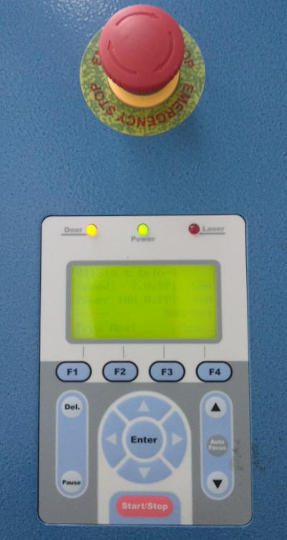
Now we close the lid, open the CO2 valve, activate the aspiration and press ‘Start’. Note: While the machine is cutting we should not leave it without supervision.
We have tested the parameters of speed and power to cut different materials.
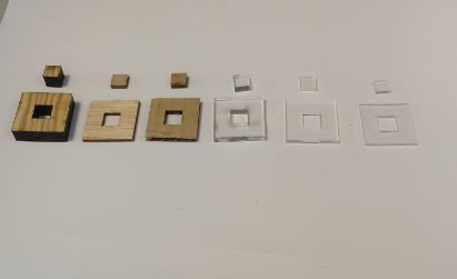
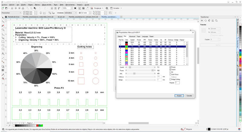
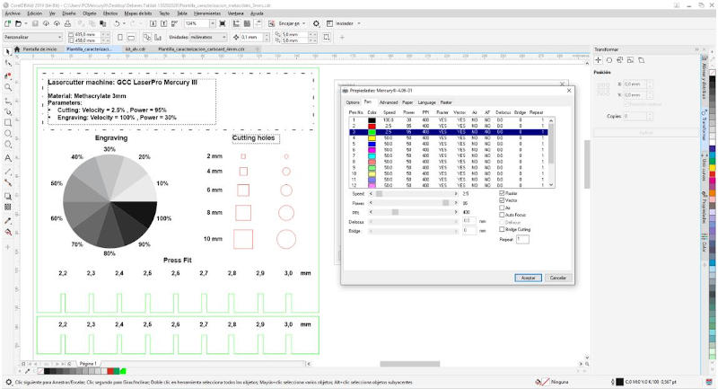
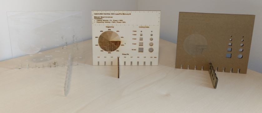
4.A.10.2. Sample templates
Finally, we cut a sample template for each material in which the parameters selected to perform it are described and it helps us to visualize the engraving of a raster image with different shades of the gray scale. It also helps us to measure the kerf and choose the pressfit.
We have taken the idea of the template of a student from last year of Fablab Barcelona, Gustavo Abreu.
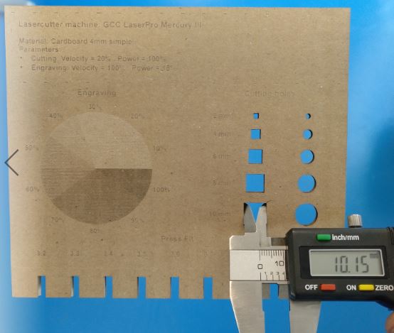
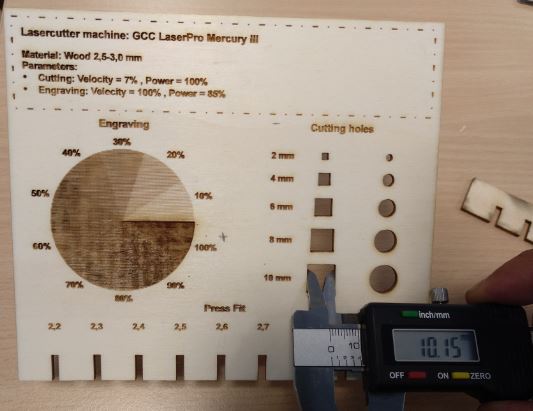
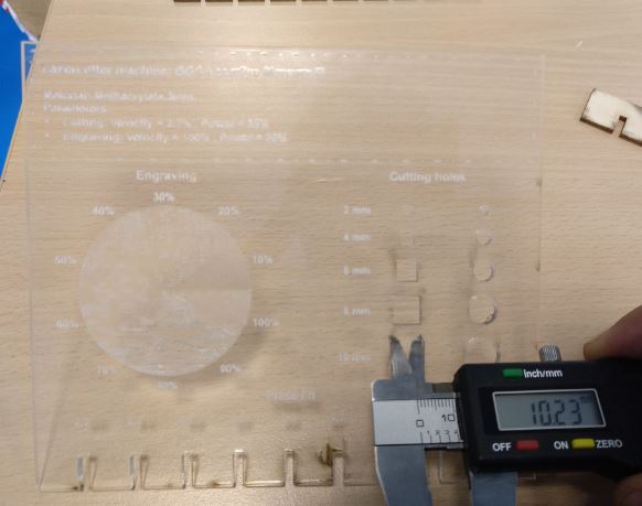
4.A.10.3. Difference and kerf
* Wood 2.5mm :
    Parameters cutting :    V=7% , P=100%
    Parameters engraving :    V=100% , P=85%
    Difference=0.15mm
    Kerf=Difference/2= 0.075mm

* Cardboard 4mm :
    Parameters cutting :    V=20% , P=100%
    Parameters engraving :    V=100% , P=18%
    Difference=0.15mm
    Kerf=Difference/2= 0.075mm

* Methacrylate 3mm :
    Parameters cutting :    V=2.5% , P=95%
    Parameters engraving :    V=100% , P=30%
    Difference=0.23mm
    Kerf=Difference/2= 0.115mm
4.B. INDIVIDUAL ASSIGNMENT
Cut something on the vinylcutter.
Design, lasercut, and document a parametric construction kit, accounting for the lasercutter kerf, which can be assembled in multiple ways, and for extra credit include elements that aren’t flat.
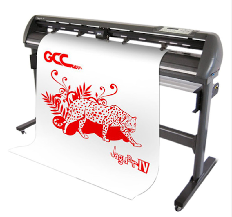
4.B.1. Vinyl Cutter
The cutting equipment used for the development of this assignment is:
JJAGUAR IV Vinyl Cutter 132cm Width
Its main features are:
-
0.1 mm accuracy
-
0.8mm maximum cutting thickness
-
Maximum cutting width 52 ”
Other features:
Media thickness 0.8mm, 600Gr. Cutting force, 1530mm/sec cutting speed, 4M memory buffer, DC Servo control with Guaranteed 10m tracking capability and Cameras With Enhanced AAS II System (Accu-aligning System) for crop marks reading to enable print and cut functionality, direct printing from Corel, USB 1.1, //, & serial connection. HP GL, HP GL2 Language.
The software associated with this equipment and the printing plotter is: RIP Onyx PosterShop and PosterPrint for managing print jobs and media profiles, and for de vinylcutter GreatCut 3 software.
4.B.1.1 My vinyl cutting job
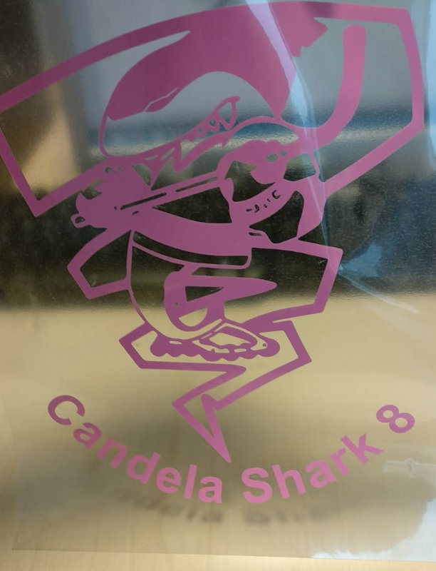
For this assignment I will cut a vinyl for a shirt. My little daughter, Candela, is part of a roller hockey team and the logo of her team is a shark, since her team is named “The Sharks.” I thought it was a good idea to personalize a shirt with the logo and its name and player number in your favorite color, pink. (Although she is a tough rival as a tuburon, she is still a 9-year-old girl who likes the color of princesses).
I started from the image start rasterized and in color.:

It is of very poor quality and the first thing I should do if I want your shirt to look pretty is to vectorize this image.
This time I choose Adobe Illustrator to do it. First, the colors in the image are oversaturated so that the areas stand out better.
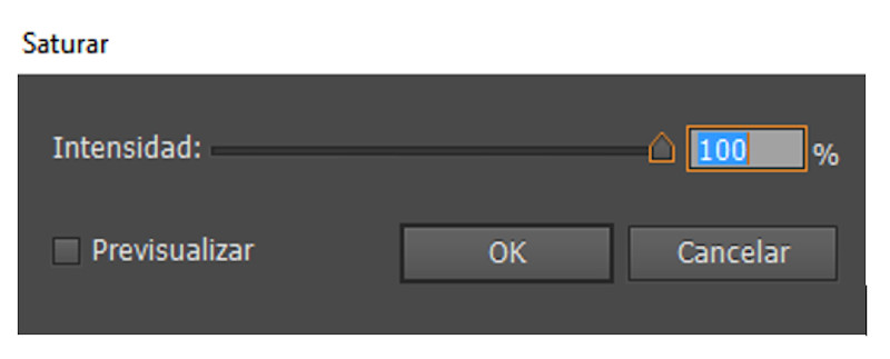
This is the first result.

It is converted to grayscale to simplify recognition.

The last step is to vectorize the image.
These are the parameters used for it.
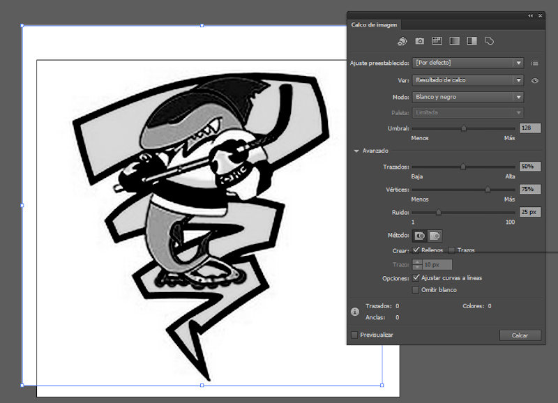
The result of the transition from raster image to vector is this:

To prepare the vinyl cut of the contour of our hockey player shark, we obtain the strokes on a transparent background in this way:
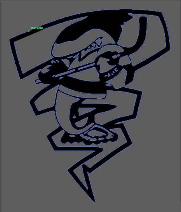
The stroke is assigned as a cutting contour to make the vinyl cut.
To personalize this logo, I put the name of the Candela shark with her player number. Entering contour lines for the cutting plotter what I get is this:

I have to change it to eps format so that the cutter can manage this format.
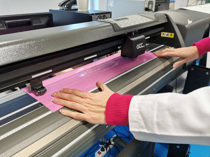
Once the image is vectotized and the cutting contours defined, the vinyl must be placed on the cutter.
Then, the work area is specified from the GreatCut3 software associated with the cutter.
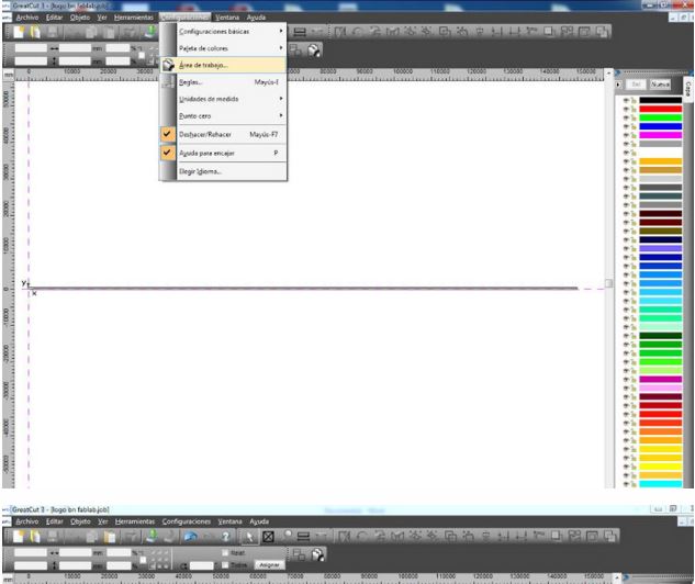
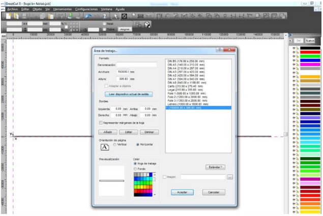
The previously generated eps file is imported.
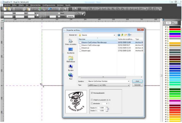
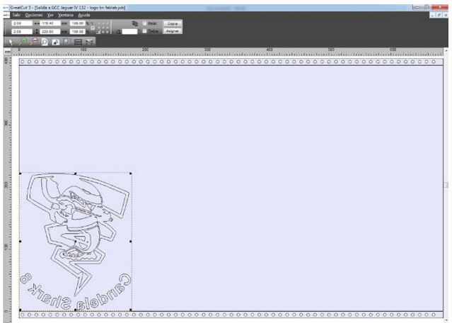
After importing, from GreatCut3 the image is shown with these lines.
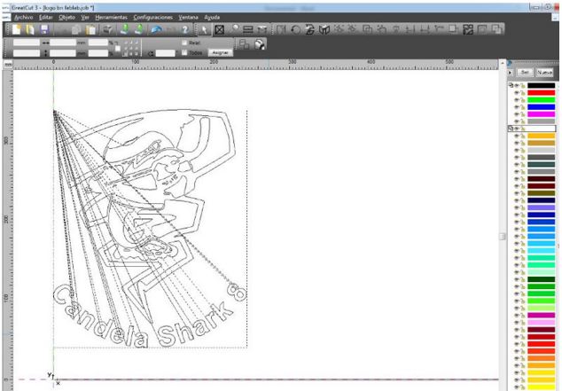
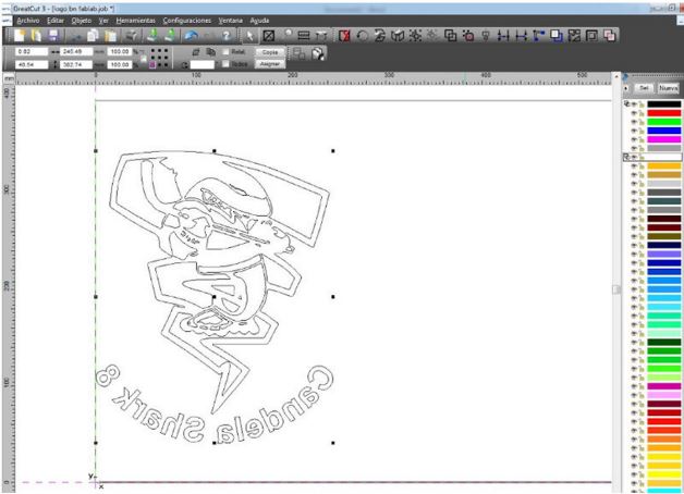
In order for the cut to be successful, I must place the image in a mirror.

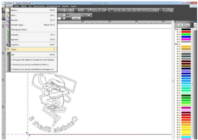
To give the cut order, the Output option is selected from the File tab.
The cutting parameters are configured.
It is always advisable, before sending to court, on this window to press for preview and see the cut that will make the equipment.
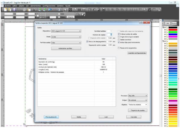
This would be the preview, this window is closed and File -> exit is pressed again, and now here you have to configure the final cutting parameters (mode, speed, blade pressure, number of passes …) as shown for this type of material.
As additional insurance in the event that a correct reading has not been made, or we have not adjusted the width of the work area well, before making the cut, you can press the “read” button in this same window, and the program , will readjust the width of the material on which we are going to cut.
The result of this whole process is this:
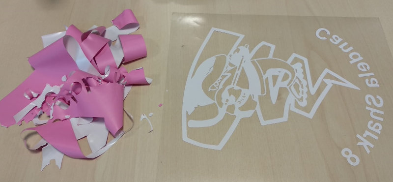
This vinyl cut, I have placed on the shirt where I want to fix it.
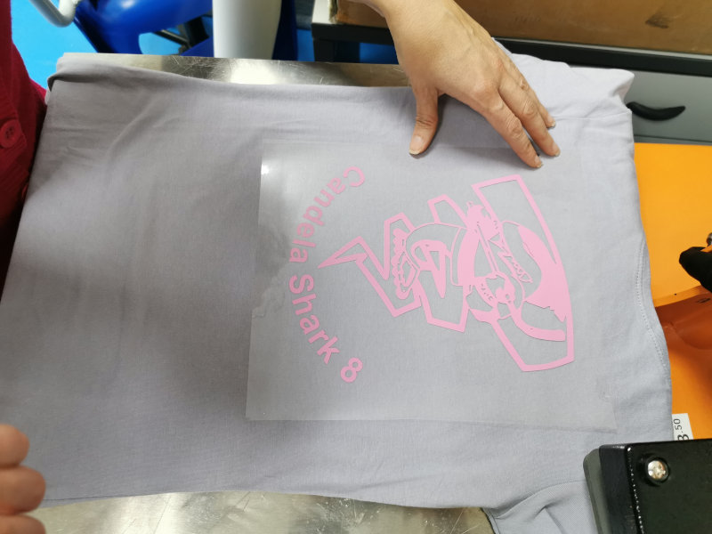
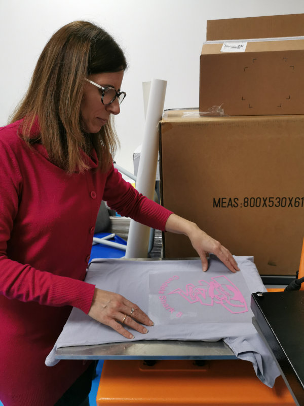
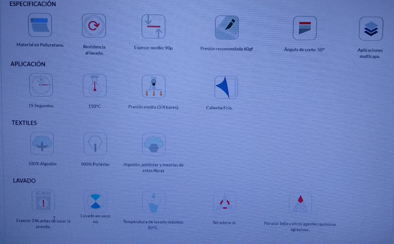
Using a special plate for vinyl printing, I was able to get the shirt that I am going to give to Candela.
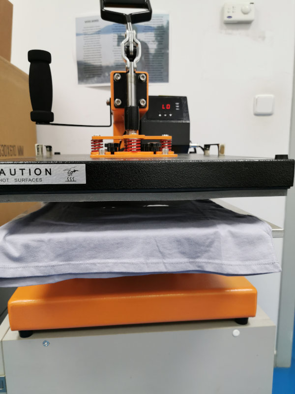
And setting the parameters specified by the machine. In this case, setting the temperature to 150º C and pressing for 15 seconds.
That has finally been like this:

She will love it !!
4.B.2. Parametric design and laser cutting
After overcoming the problems of characterization of the laser cutter, in the group assignment, due to the qualities of the cardboard, I have finally been able to see my parametric design cut.
The problems we had were due to the fact that Álvaro and I first used a cardboard that we recycled from a packaging, while the one we had bought to carry out this practice, came to us.
We thought that the one on the way would be of the same or even better quality than the one we were using, but unfortunately it has not been. In addition to arriving too late and delaying our assignment, it arrived deteriorated and its quality leaves much to be desired.
4.B.2.1. Parametric design
My idea:
When I was a child, at school, we did, as a pre-technology activity, a ball with felt cut with shapes of pentagons and hexagons and sewn together. I remember this activity and I liked to get that shape from pieces of cloth. That ball is still going around my parents’ home.
It was like a football ball, now I can think of making one similar with cardboard.
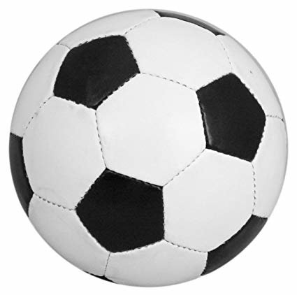
For my parametric design I started with the idea of forming a “football ball” with cardboard pieces cut in the laser cutter, looking for sources of information, in fabacademy, I found similar works done by previous students, specifically I have based on the work done by Borja Lanza in 2016.
I consulted this idea with my instructor Nuria and she gave me more than one clue. Thanks Nuria, you are a sun.
In my case I have made the parametric design of six different pieces, from the SolidWorks software.
I started with hexagons and pentagons, which assemblies can become something similar to my idea.
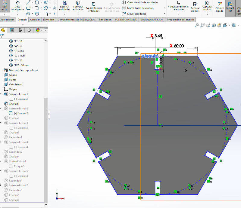
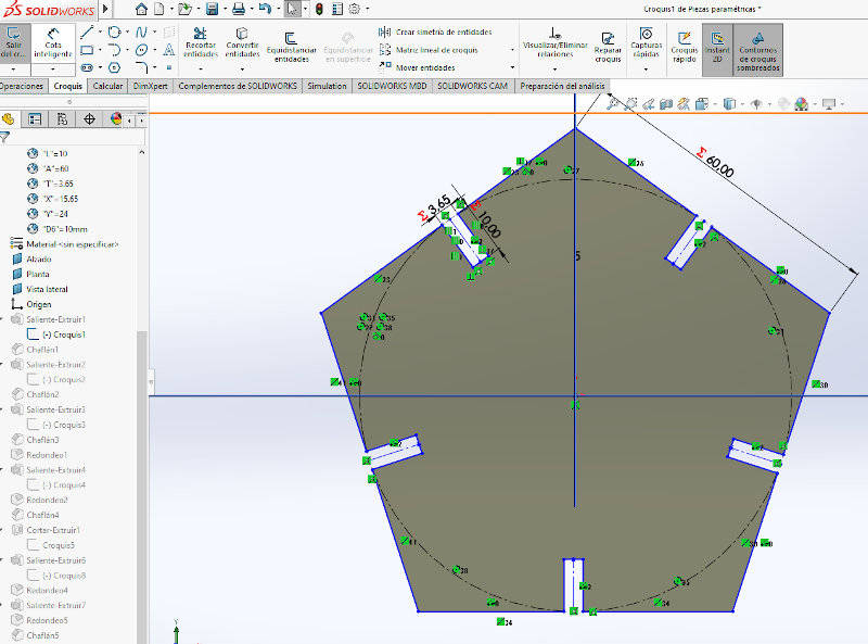
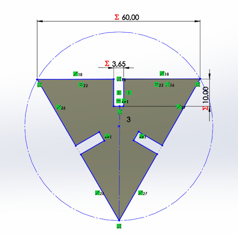
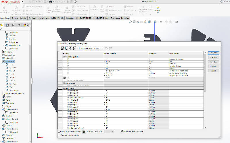
From a 2D sketch, I have created variables and equations that relate some dimensions to others in order to create my geometric figures as a parametric design.
Then I designed the slots that will serve me to assemble some figures with others, here, to the thickness of the cardboard in which I will manufacture the logs, I have applied the value of the kerf obtained in the group assignment and the value of the pressfit to adjust so correct some pieces with others.
I have also designed the pieces that will serve as a union for my hexagons or my pentagons or my hexagons with pentagons…
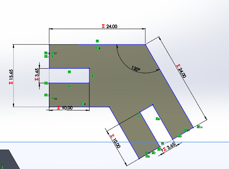
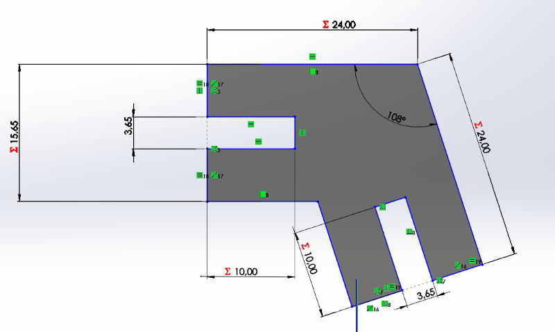
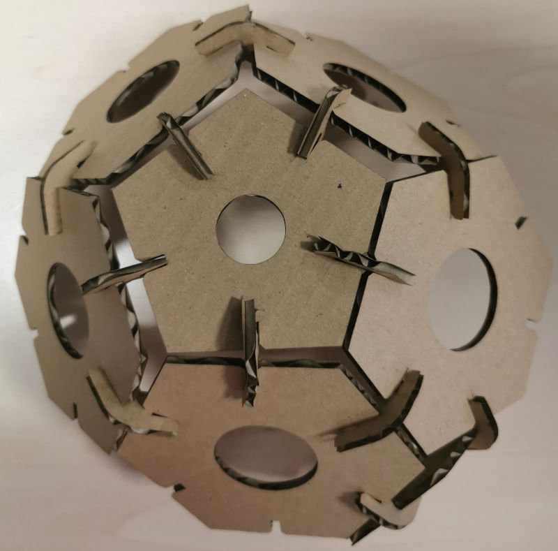
These connections form angles of 108º and 120º and will help me to achieve the form of truncated icosahedron that I am looking for, which is actually the way in which the foofball ball is based.
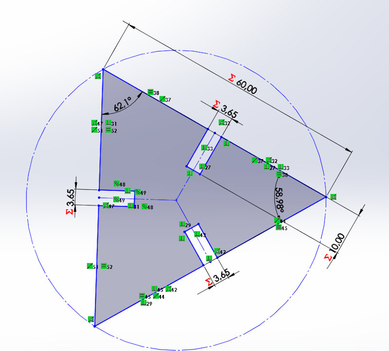
I have also created two types of triangles, which together form a pentagon or a hexagon, with them I will see if I am also able to make some other form.
All parts have a chamfer for easy assembly. And some of them are rounded.
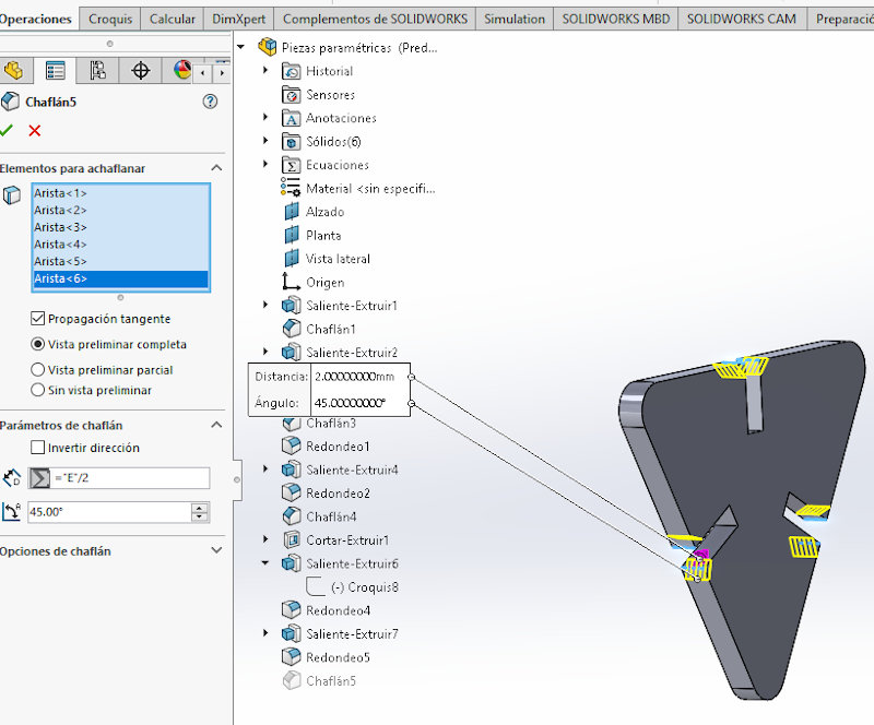
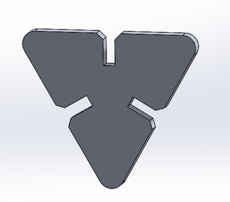
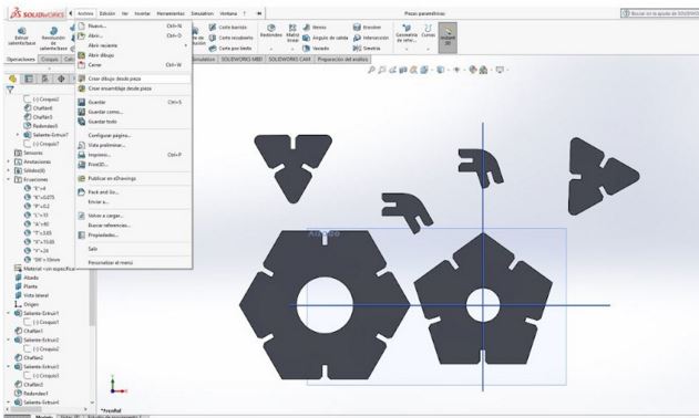
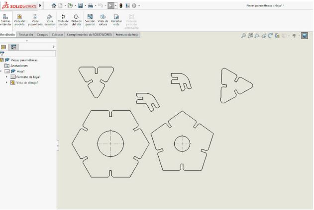
The result of the pieces designed with an extrusion to create them in 3D, is this:
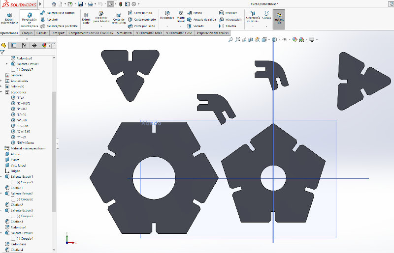
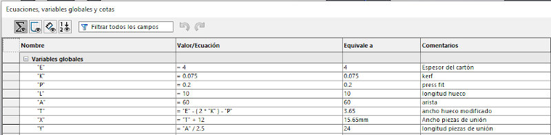
Variables and their equations are collected in the following table generated in Solidworks.
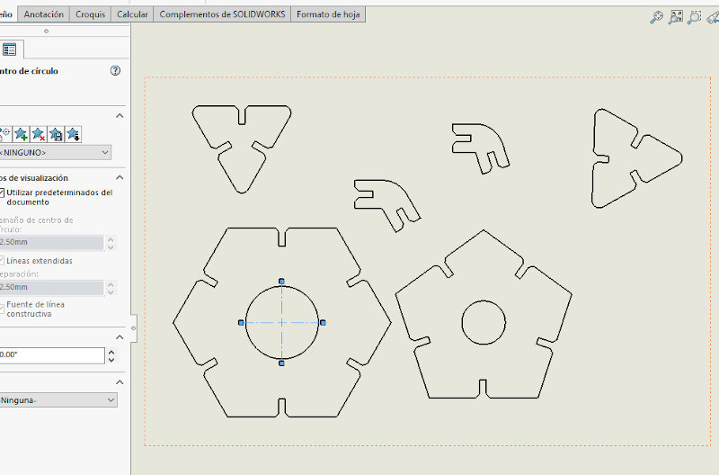
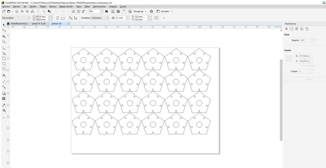
Once the pieces have been generated, from Solid I obtain the cutting contours, generating a plane with the flat shapes.
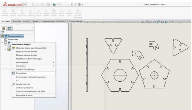
I make sure they are at 1: 1 scale.
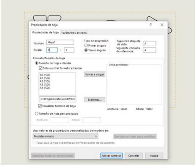
I eliminate the axes and elements that can lead to error.
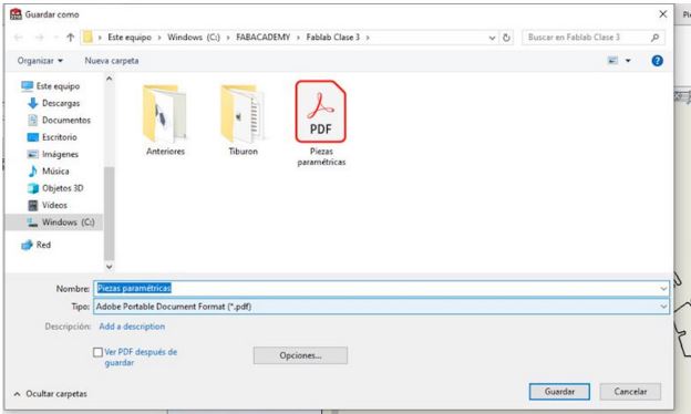
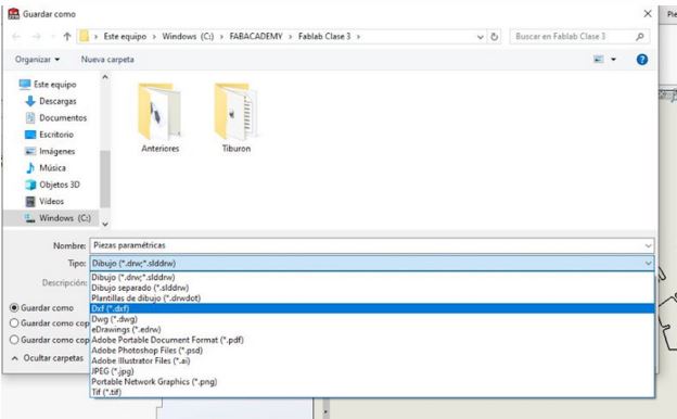
I save the file with two different formats: pdf and dxf to try cutting on my laser cutter.
Finally I used the pdf file.
From these files I will generate my cut pieces.
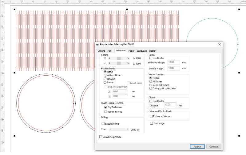
4.B.2.2. Laser cutting
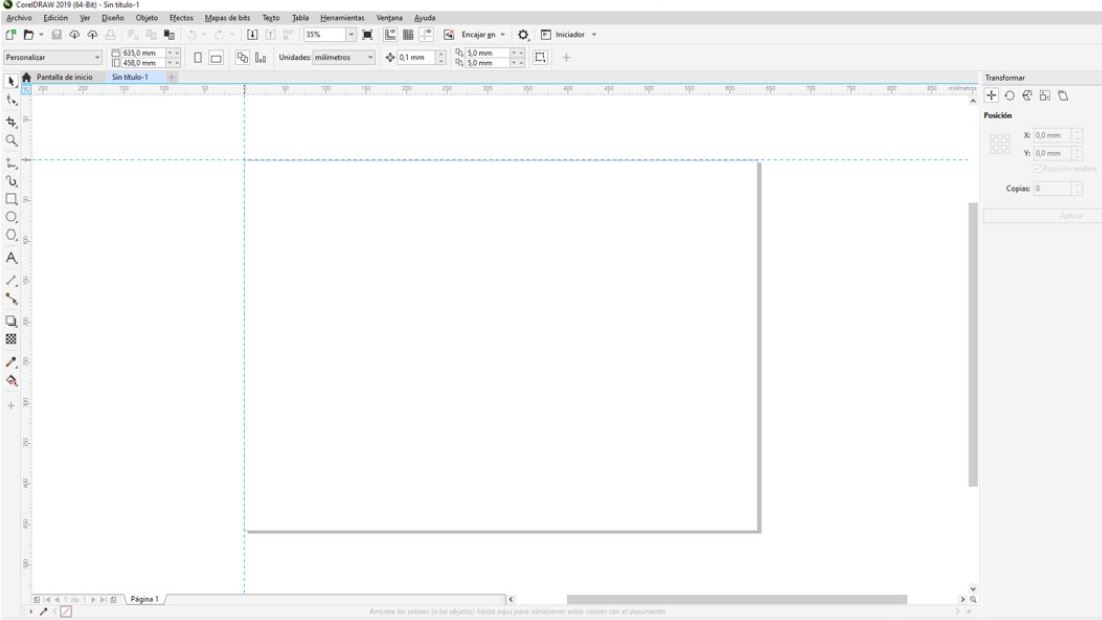
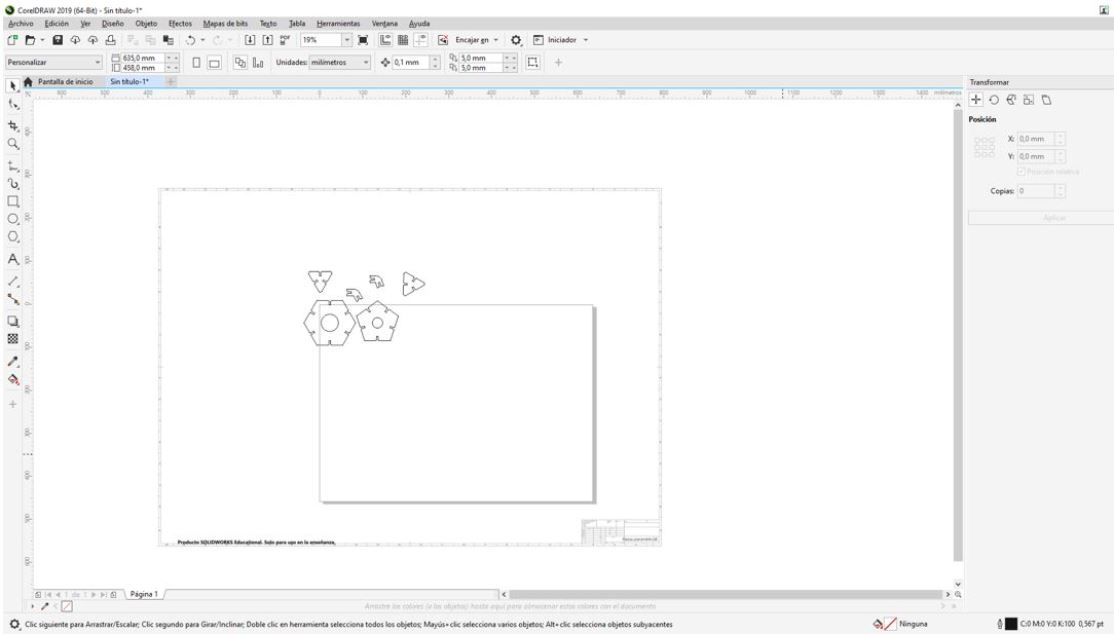
The software of the laser cutting machine in our case is Corel Draw.
From this software, I open a new blank document with the maximum dimensions of the machine. And I place the zero machine in the upper left corner of the sheet.
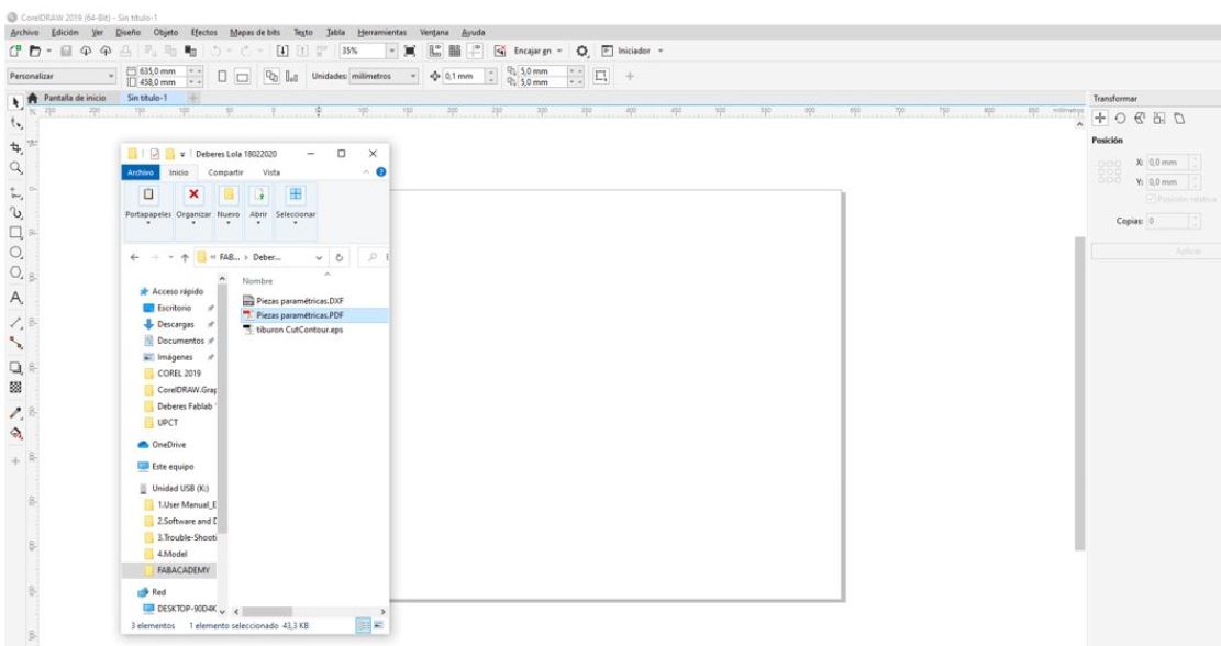
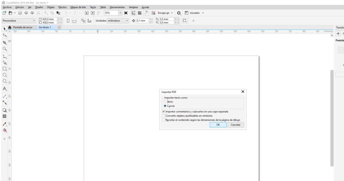
I drag the pdf file with the pieces
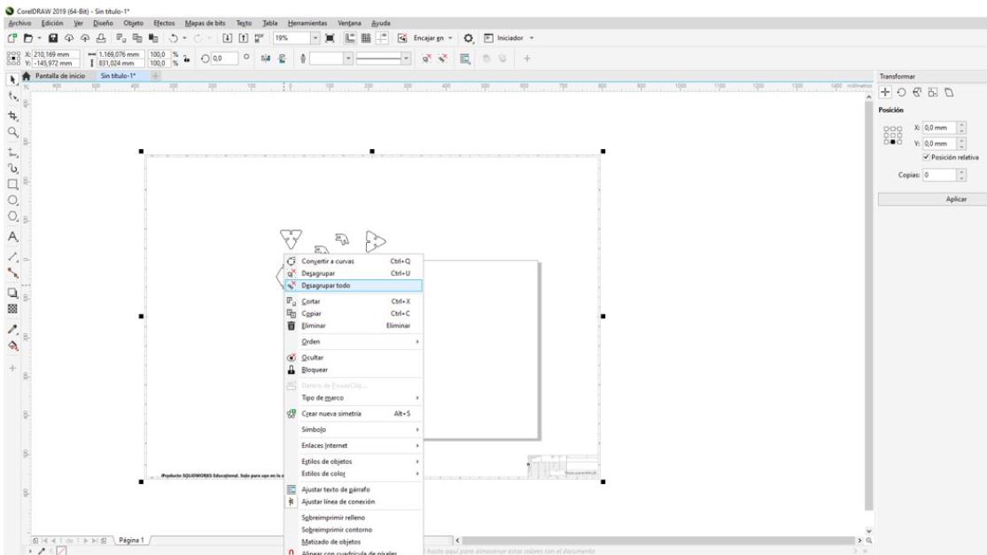
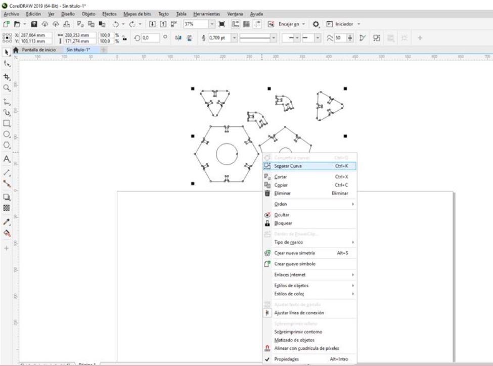
I select the imported image and with the right mouse button I select ‘Ungroup all’ to be able to eliminate what I don’t want.
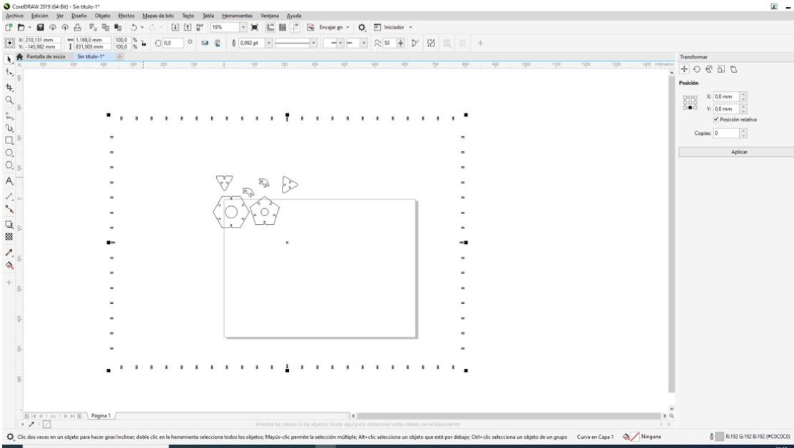
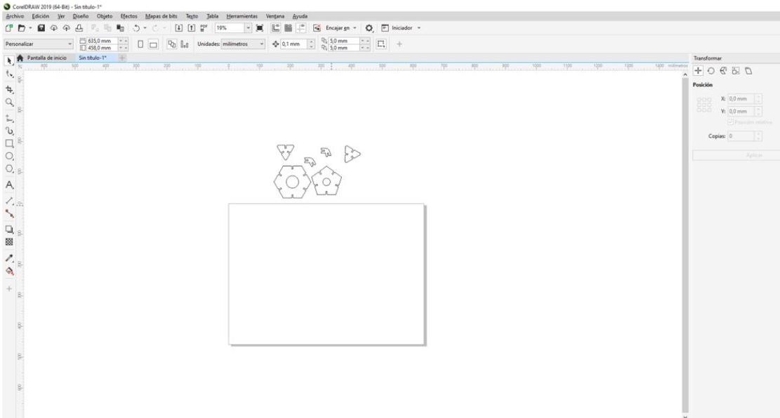
Select the pieces and make ‘separate curves’ to move them independently.
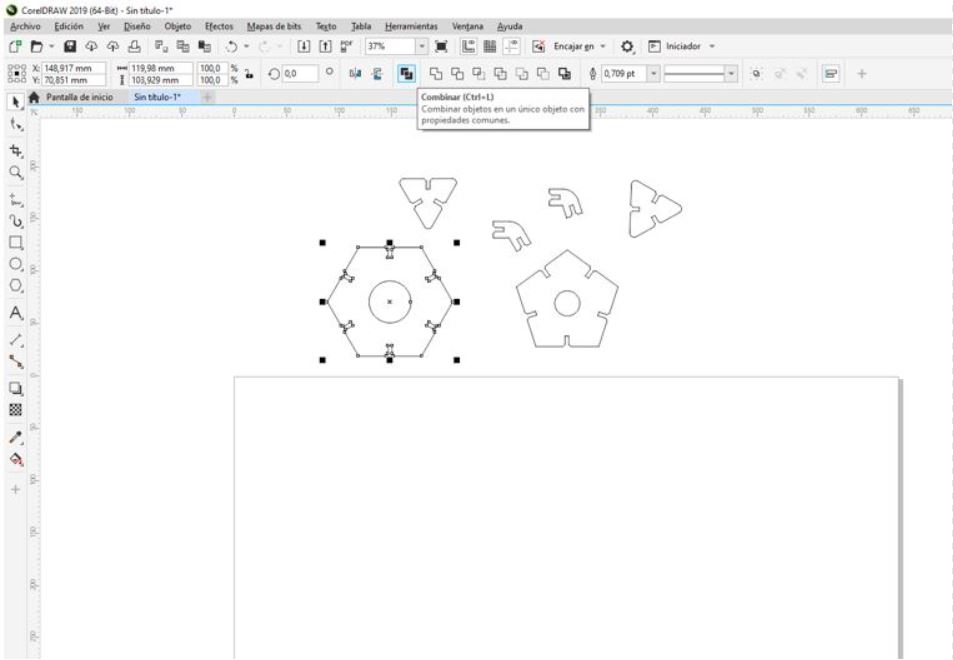
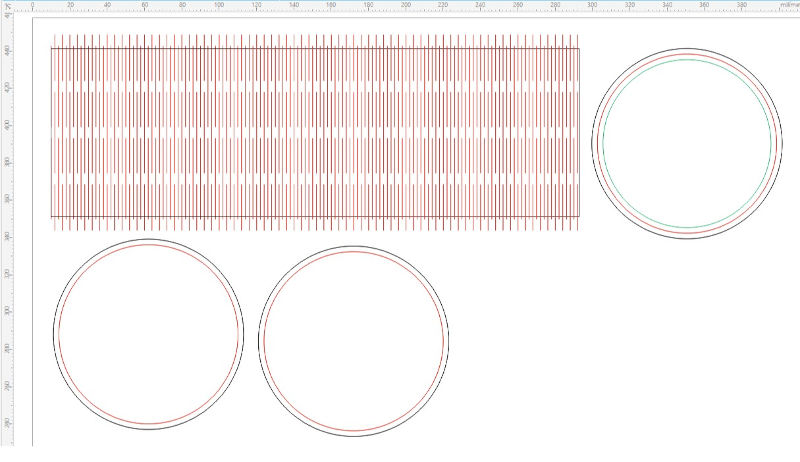
I put the first piece and its copies and select a “very fine” line since I’m going to make a cut.
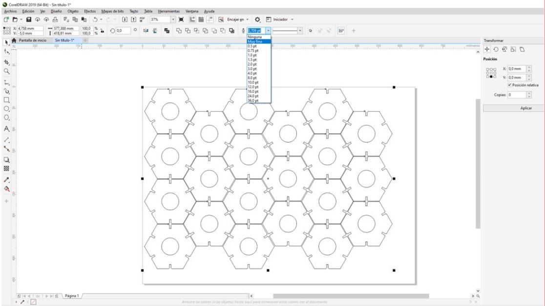
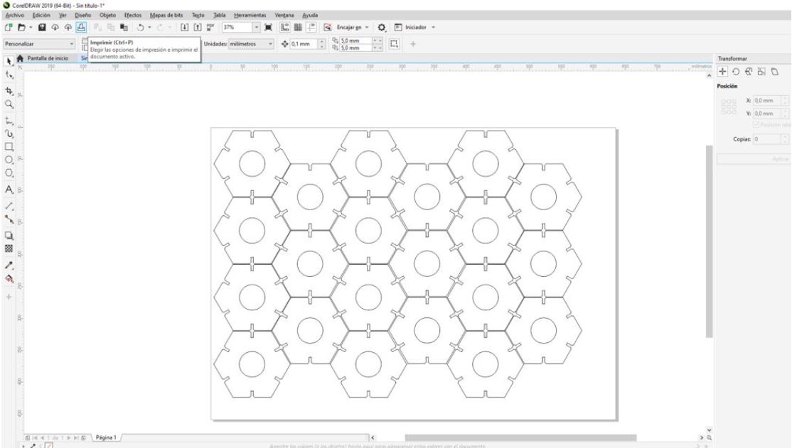
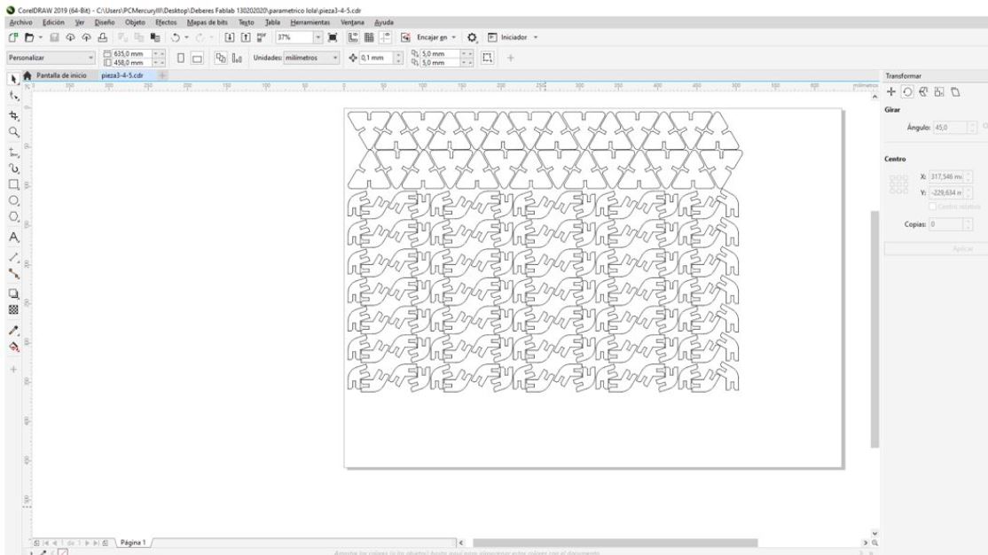
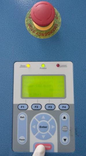
With all this ready, I put three sheets of cardboard, one behind the other in the cutter and sent back to cut my files.
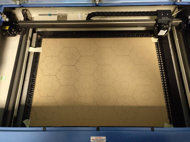
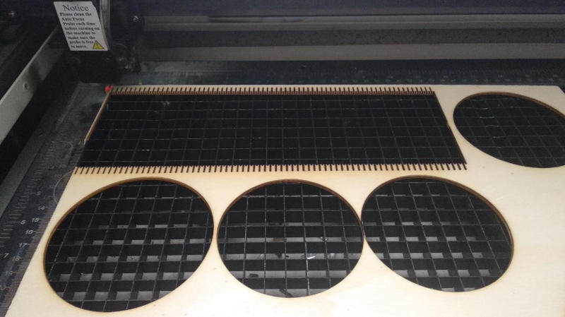
The parameters used for speed and power are those confirmed by Alvaro and I in the characterization of the machine for this material, cardboard, and are 20 for speed and 100 for power.
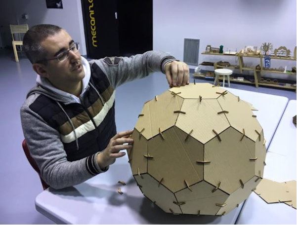
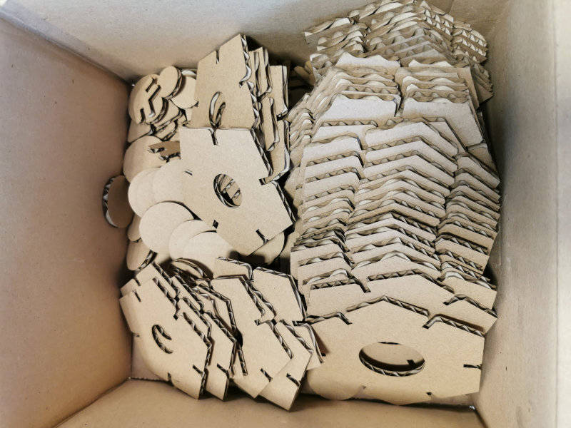
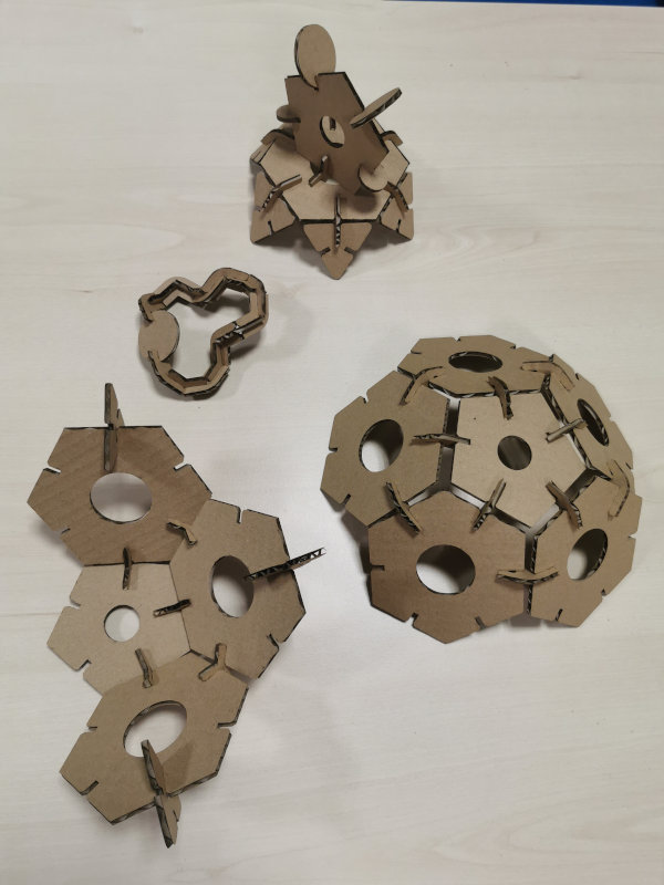
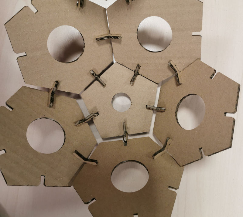
In this way, I now have a lot of pieces to start playing.
I have managed to make multiple forms, although the beautiful ball that I thought has remained in half orange.
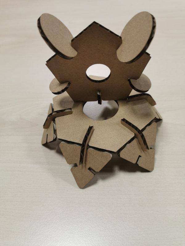
4.B.3 Design and cut elements that are not flat
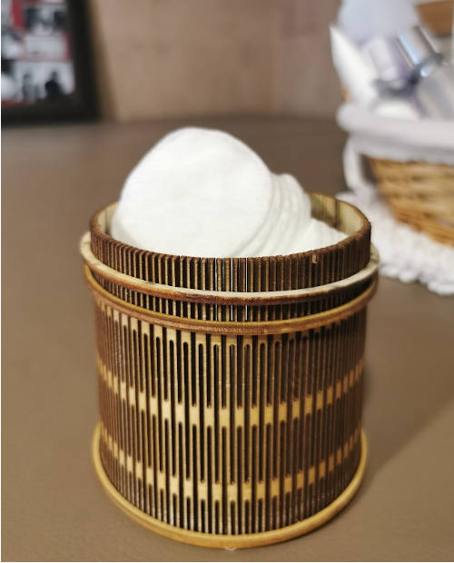
For this section, I want to try designing a cylindrical container with a base, which can be manufactured by laser cutting and then can be used to store things on my desk in my office or at home, the use will depend on the result…
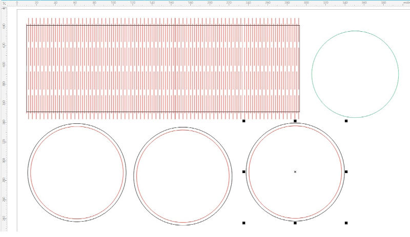
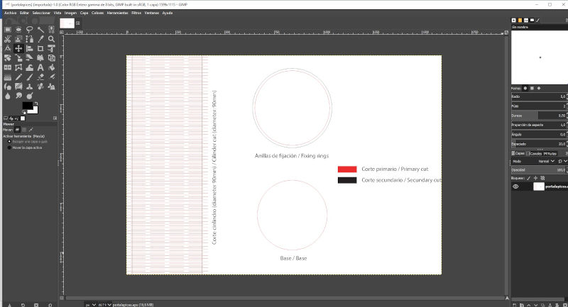
First I have drawn the pieces that will form the container in Adobe Illustrator, it will be a circular base, and for the fastening I first thought to put a kind of slotted washer to fit the thickness of the side of the cylinder, and I made this design:
Later I thought about updating the design based on the geometry of the wine and beer barrels, which have a round circular base, surrounded by the curved cylindrical wall that is externally fastened with rings, in this case of the same wood, the new design is this:
From Illustrator I saved the file to the eps format.
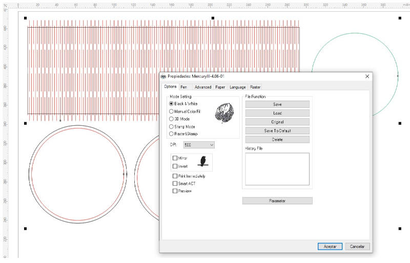
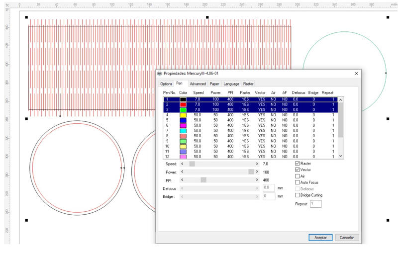
Y I configured the cutting parameters for the Mercury III laser cutter and this type of material.
The parameters indicated for the wood are 7% speed and 100% power, for our 60W laser.
I gave the order to the machine to make the cut:
The cut was made, I removed the parts from the machine.
I did the montage, and the result was this:
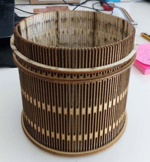
Now, I already have this nice container in use.
4.B.4 Links to download my files¶¶
Templates for laser cut characterization:
My parametric kit for laser cutting cardboard pieces:
My image for cutting plotter: