2. Computer Aided design
Assignment
Model (raster, vector, 2D, 3D, render, animate, simulate, …) a possible final project, and post it on your class page.
Outcome
Here is a video of the completed model built with 3D CAD with a bit of rendering and a diagram of components made with 2D CAD.
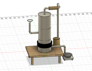
This is the screen shot of the 3D model.
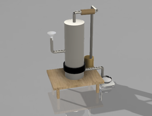
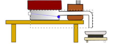
And how it is like after a bit of rendering.
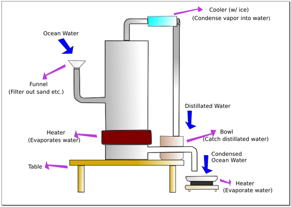
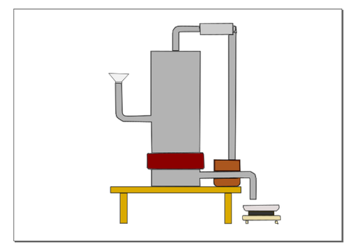
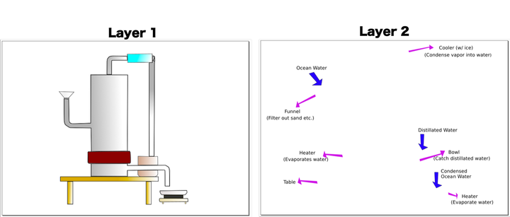
And the diagram of components.
3D CAD
3D modeling
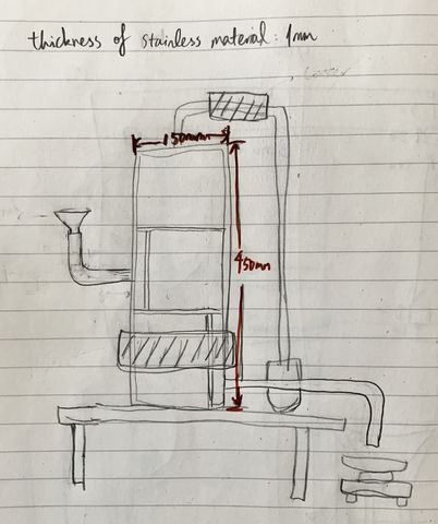
I first used Fusion 360 (which I am more familiar with) to complete the model based on this sketch.
I built the model in the order of:
- distillation tower: body -> inside -> pipes
- table
- funnel
- bowl for condensed water
- hot plate
- pan
- cooler
- heater
Distillation tower
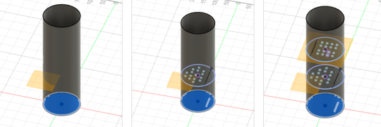
I sketched the bottom circle, extruded the bottom, and extruded the wall of the cylinder.
Then I created offset plane for the inner plane, sketched tiny circles as the holes, extruded that surface, and added vertical wall so the liquid can fall down along that.
And of course I added the top of the body.
Then I added pipes to the body.
I followed the instruction of this video.
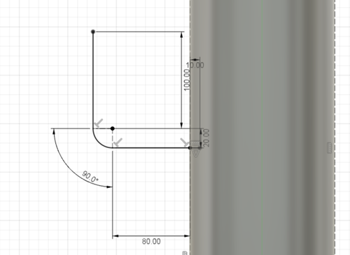
Firstly, I sketched the center line of the pipe:
- Set the plane that cuts through the middle of the tower’s body as the offset plane
- Draw a 80mm line starting from the body
- Draw a circle with a diameter of 40mm touching the line
- Draw another line of 100mm extending from a quarter of the circle
- Trim the 3/4 of the circle that is not on the path
- Draw a 10mm line inward starting from the surface of the tower body, so that the pipe is attached to the tower body
And then I made the pipe using “pipe” function in “create” with the following settings.
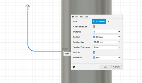
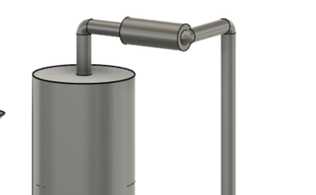
Combining this function and switching planes, I even made this pipe that zig-zags within the space.
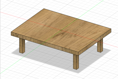
Table
I sketched and extruded a rectangle as the surface of the table, sketched 4 small squares and extruded them as the feet of the tables.
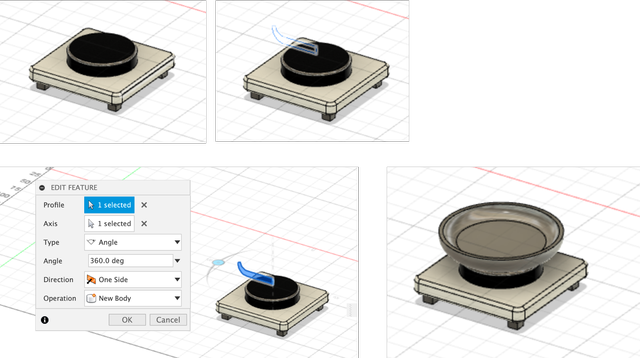
Hot plate
The heater part of the hotplate was created in the same manners as the table.
A cylinder shaped heating part was also added to it.
And the pan was created with rotation of a vertical shape.
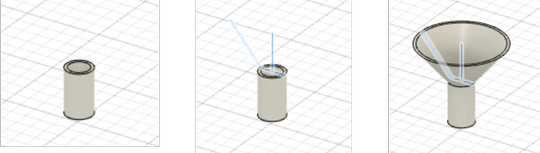
Funnel
Funnel was created with firstly a cylinder as the lower part, combined with the upper part with rotation.
Heater & Cooler
Heater and cooler are created as cylinders.
Bowl for condensed water
Bowl for condensed water was created by the sketch of the sectional view and rotation.
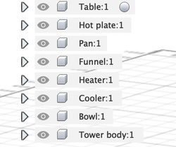
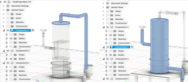
Setting up components
I renamed all the components so it’s easier to identify.
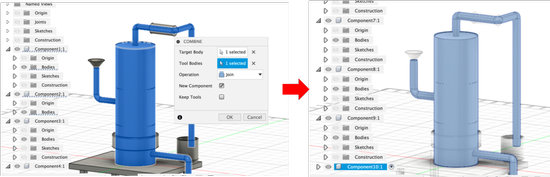
And then I tried to combine different components into one.
Somehow the tower body and the upper pipe are created as different components and I wanted to merge them into 1 single component.
I followed this tutorial.
I combined the 2 bodies and it generates a new component - component 10.
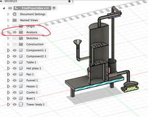
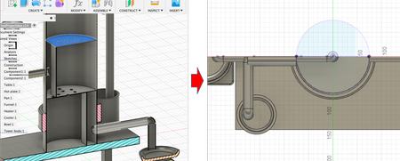
Inspecting sections
Using “section analysis” in “inspect”, I can inspect the inside of the model. The view is created as “analysis”. And from there, I can make sketches based on the view.
3D rendering
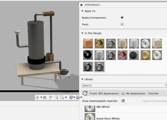
I used Fusion 360 to render my model at render workspace.
I firstly changed the appearance to simply drag the desired texture onto the model. I select “body/component” when I want to whole body/component to be the same texture, and “face” when I want the body to have different textures (for example the hot plate).
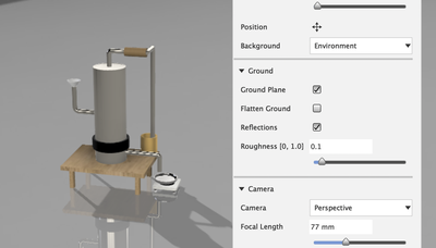
And then I tried changing the scene settings. I tried changing the lighting style in Environment Library, brightness, position, reflection, and background in Settings.
2D CAD
I used Inkscape to draw a diagram explaining the components.
I imported a screenshot of the 3D model.
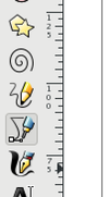
And I activated the “Draw Bezier curves and straight lines” function.
I clicked dots to connect lines along the outer edge of the model.
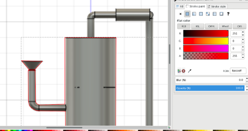
After drawing all the lines, I deleted the screenshot of the 3D model, and painted the parts.
There were 5 learning outcomes.
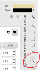
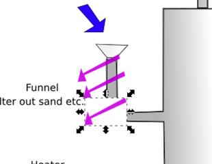
The 1st learning out come is to disable snapping.
When it’s enabled, the lines automatically snap to the edges of exisiting lines. I couldn’t draw lines as I want.
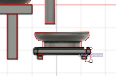
This button is to enable/disable the snapping function.
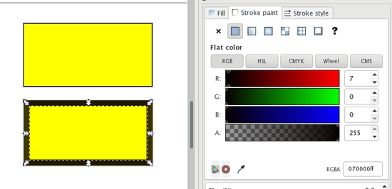
The 2nd learning outcome is about the setting of painting. The rectangle above is painted with out stroke, and the second is painted with stroke. When with stroke, every time of painting increases the outline of the rectangle.
The 3rd learning outcome is gradient painting function. I used the “Create and edit gradient” function.
I adjusted the lines and dots to adjust the appearance of the gradient. The drawing turns out to be like this:
The 4th learning outcome is using layers. I sketches the components in layer 1, drew arrows and edited texts in layer 2.
The 5th is the difference between duplicate and copy&paste. When duplicate, the item stays opaque. When copy&paste, the item looses opacity and the surrounding is painted white. (the 1st one is the original, 2nd is duplicated, 3rd is copy&pasted)
Trying out other tools
FreeCAD
I tried FreeCAD to make this:
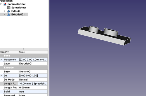
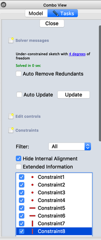
I found the concept being similar to Fusion 360. The actions to take and interface can be a bit different. For example, I thought the list about constraints is more obvious.
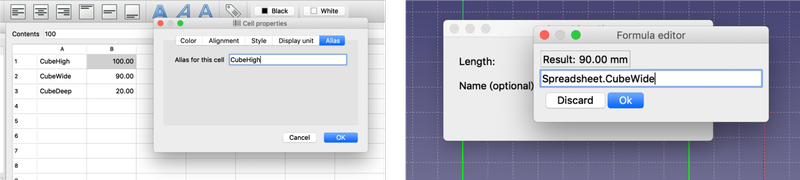
And parametric design includes this spreadsheet. The interface was a bit different from Fusion 360.
Overall, I’m very impressed by the functions it has as a free software.
GIMP
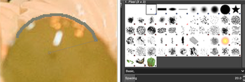
I tried out GIMP.
It was fun to see different kinds of brushes. And when zooming in, I could see how it is raster based.
I went through a tutorial, and was able to add text, shadow to the text, and a background for the text.
I think I like the interface of GIMP better than Inkscape…
Comparison between raster and vector data
- Raster data stores information of features in cell-based manner, it consists of pixels. Each pixel has an associated value. A grid of cells represents this data. In other words, it is a matrix of cells organized into rows and columns. Each cell has a value that represents information.
- Vector data uses sequential points or vertices to represent data. Each vertex contains x coordinate and a y coordinate. It is used for storing data that has discrete boundaries.
Comparison between different file formats
- SVG (Scalable vector graphics): SVG uses shapes, numbers and coordinates rather than a pixel grid. So the quality of image would not change by scaling.
- DXF (Drawing Interchange Format or Drawing Exchange Format): Commonly known as AutoCAD DXF format, is a CAD data file format. It was developed by Autodesk to enable data interoperability between AutoCAD and other programs.
- PNG (Portable Graphics Format): a raster-graphics file format that supports lossless data compression.
- F3D: 3D design file created by Autodesk Fusion 360, a cloud-based 3D CAD design tool; contains your 3D design created by the latest mechanical and industrial design tools designs
After week 2
- Modeling the final project helps me understand/specify about how the various components should make up the whole installation. Before I was just planning on hanging the bowl for the distillated water in the space :p
- I’m getting comfortable using Fusion 360. It seems to work well with shapes that can be made from simple shapes like trangle, circle, and line. And the rendering was simple to make.
- Inkscape is awesome as it is free to all. However the shortcuts can be a bit frustrating when working on Mac. And the painting settings can be more intuitive.