9. Input devices
Assignments
- individual assignment:
- measure something: add a sensor to a microcontroller board that you have designed and read it
- group assignment:
- probe an input device’s analog levels and digital signals
Group assignment
Since I couldn’t get access to the lab this week, I wasn’t able to use a oscilloscope to probe the signals.
Other students who were able to access will update the assignment page.
Breathalyzer
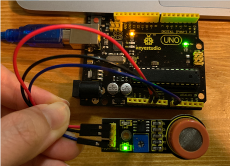
I made a breathalyzer with MQ-3 alcohol sensor that tells you if you had alcohol or not when you breathe on it.
How does MQ-3 work
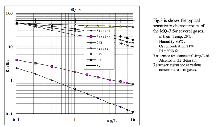
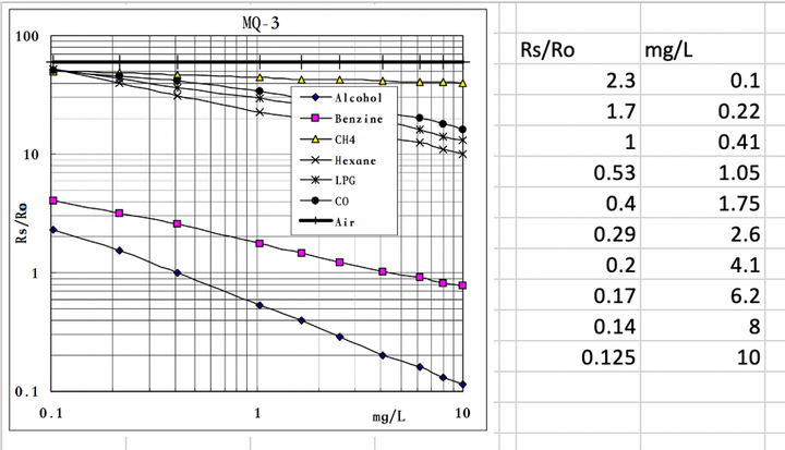
According to the datasheet, and this page MQ-3 uses sensitive material SnO2, whose conductivity is lower in clean air. It’s conductivity increases as the concentration of alcohol gases increases. It has high sensitivity to alcohol and has a good resistance to disturbances due to smoke, vapor and gasoline.
Reading the digital values from the sensor
I used Arduino board and MQ-3 alcohol sensor.
I followed this page of Keyestudio Wiki.
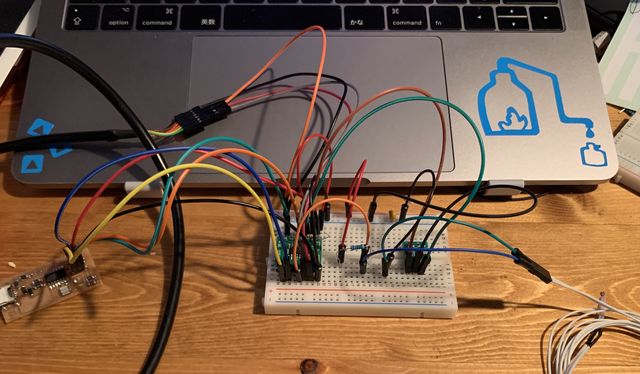
I connected MQ-3 to Arduino board with:
MQ-3 VCC to Arduino 5V,
MQ-3 GND to Arduino GND,
MQ-3 A0 to Arduino A0.
I set board to “Arduino/Genuino Uno”, programmer to “Arduino as ISP”, compiled and ran this program on Arduino IDE:
///Arduino Sample Code
void setup()
{
  Serial.begin(9600); //Set serial baud rate to 9600 bps
}
void loop()
{
int val;
val=analogRead(0);//Read Gas value from analog 0
Serial.println(val,DEC);//Print the value to serial port
delay(100);
}
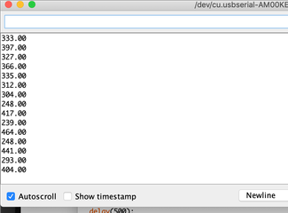
I opened serial monitor on Arduino IDE, set baud rate to 9600, and observed the number.
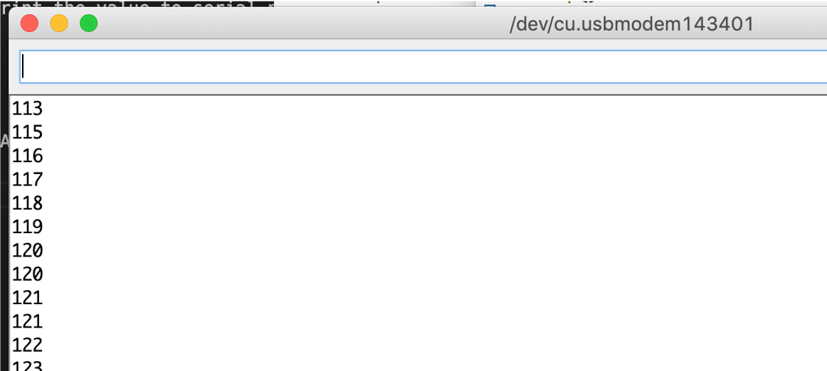
In here, the number goes up if the concentration of alcohol gets higher. Since the conductivity gets higher when alcohol exists.
Connect to an LED
And then I programmed the board’s LED to blink faster when detecting higher alcohol concentration.
I combined a blink program to the alcohol sensor program.
The LED blinks every second when the alcohol level is low, and every 0.1 second when the level is high.
///Arduino Sample Code
void setup()
{
  Serial.begin(9600); //Set serial baud rate to 9600 bps
  pinMode(LED_BUILTIN, OUTPUT);
}
void loop()
{
int val;
val=analogRead(0);//Read Gas value from analog 0
Serial.println(val);//Print the value to serial port
delay(100);
if (val>200)
{digitalWrite(LED_BUILTIN, HIGH);   // turn the LED on (HIGH is the voltage level)
  delay(100);                       // wait for a second
  digitalWrite(LED_BUILTIN, LOW);    // turn the LED off by making the voltage LOW
  delay(100);                       // wait for a second
}
else
{digitalWrite(LED_BUILTIN, HIGH);   // turn the LED on (HIGH is the voltage level)
  delay(1000);                       // wait for a second
  digitalWrite(LED_BUILTIN, LOW);    // turn the LED off by making the voltage LOW
  delay(1000);                       // wait for a second
}
}
Connect with LCD display
Then I connected an LCD display (SD1602HULB-XA-G-G) to the sensor and Arduino.
It seemed to be a Japanese product, all the information I can find was in Japanese.
I refered to this [page(Japanese)] (http://www.techand.jp/Digital/Arduino/Char_LCD.html).
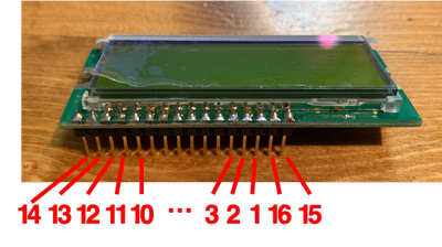
These are the configurations of Arduino and LCD.
The pins on the LCD is numbered as below.
| Arduino | LCD |
|---|---|
| GND | 1, VSS |
| 5V | 2, VDD |
| 3 | V0(contrast) |
| 12 | 4, Rs |
| 11 | 5, R/W |
| 10 | 6, Enable |
| 5 | 11, DB4 |
| 4 | 12, DB5 |
| 3 | 13, DB6 |
| 2 | 14, DB7 |
| 15, BL+ (Backlight) | |
| 16, BL- (Backlight) |
I connected the pins as the image in the page.
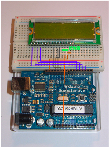
I connected the green resistor for contrast. The page said that the resistor connected between V0 and GND to adjust the contrast is 3.3K Ohm. I only had 4 499Ohm resistors so I connected all of them.
The page also advises to connect a resistor that is between 20-100Ohm between 16 pin +5V. But I didn’t have so I didn’t connect it.
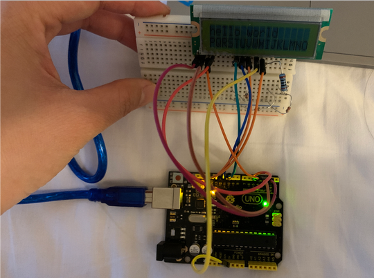
You can see from the picture that the contrast is still a bit weak.
For programming, I combined the one for LCD display with the previous program. It displays “drunk” when the alcohol level exceeds a certain level, and “sober” when below.
#include <LiquidCrystal.h>

LiquidCrystal lcd(12, 11, 10, 5, 4, 3, 2);

void setup()
{
  lcd.begin(2,16);

}

void loop()
{
 int sensorValue = analogRead(0);
 lcd.clear();
 lcd.print(String(sensorValue));
 delay(100);

lcd.setCursor(3,1);
if (sensorValue>300)
{
  lcd.print("drunk");
   delay(100);

}
else
{lcd.print("sober");
 delay(100);
}

}
Turns out it works!
This LCD display functions as a display, however, there are a lot of pins to figure out.
Getting results in mg/L
I wanted to get results in mg/L, so I followed this page and the datasheet of MQ-3.
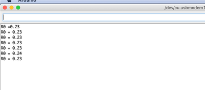
At first, I tried to run this code:
void setup()
{
   Serial.begin(9600);
}

void loop()
{
    float sensor_volt;
    float RS; // RS in the air
    float R0; // R0 in alcohol
    float sensorValue;

    for(int i = 0 ; i < 100 ; i++)
    {
        sensorValue = sensorValue + analogRead(A0);
    }

    sensorValue = sensorValue/100.0;     //Calculate the average
    sensor_volt = (sensorValue/1024)*5.0;  //PWM of Arduino is 10Bit 1024
    RS = (5.0-sensor_volt)/sensor_volt; // omit RL
    R0 = RS/60.0; // in clean air, RS/R0=60
    Serial.print("R0 = ");
    Serial.println(R0);
    delay(1000);

}
However, I got minus value for R0…
R0 = 0.23, R0 = 0.11, R0 = 0.06, R0 = 0.04, …, R0 = 0.00, R0 = -0.01, R0 = -0.01
I checked sensorValue and it turns out to be fluctuating largely which seems unnatural.
I suspected that the code for calculating the average could be wrong. (I don’t know how to fix it so I’ll ask the instructors this weekend.)
So I deleted the part for calculating the average and ran the program.
void setup()
{
   Serial.begin(9600);
}

void loop()
{
    float sensor_volt;
    float RS;
    float R0;
    float sensorValue;

    sensorValue = analogRead(A0);
    sensor_volt = (sensorValue/1024)*5.0;
    RS = (5.0-sensor_volt)/sensor_volt; // Omit RL
    R0 = RS/60.0; // RS/R0=60 in the air
    Serial.print("R0 = ");
    Serial.println(R0);
    delay(1000);

}
I understood that RS/R0=60 in the air is taken from the plot of air.
However I didn’t understand sensor_volt = (sensorValue/1024)*5.0(should have something to do with PWM) and RS = (5.0-sensor_volt)/sensor_volt;. I will research later and ask the instructors.
I got the result that R0 = 0.23.
To derive the relationship between Rs/R0 and mg/L, I wrote down the values in the plot of alcohol in Excel.
(I wonder if there is any better ways of doing it? For example if there is data I can download? Right now I’m just reading the number based on assumptions which doesn’t seem 100% reliable…)
It seems to be a logarithmic function, so I calculated the ln of all the numbers, and calculated the trendline.
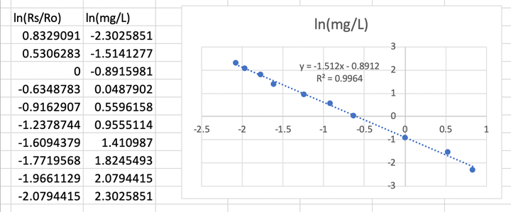
R2 = 0.996… Not too good but not too bad.
ln(mg/L) = -1.51ln(Rs/Ro)-0.89
So mg/L = 2.72 ^ (-1.51ln(Rs/Ro)-0.89) (assume e = 2.72)
I tried to ran this program:
void setup()
{
Serial.begin(9600);
}
void loop()
{
float sensor_volt;
float RS_gas; // Get value of RS in a GAS
float ratio; // Get ratio RS_GAS/RS_air
float concentration;
int sensorValue = analogRead(A0);
sensor_volt=(float)sensorValue/1024*5.0;
RS_gas = (5.0-sensor_volt)/sensor_volt; // omit *RL
/*-Replace the name "R0" with the value of R0 in the demo of First Test -*/
ratio = RS_gas/0.23; // ratio = RS/R0
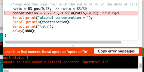
concentration = 2.72 ^ (-1.51ln(ratio)-0.89) //in mg/L
Serial.print("alcohol concentration = ");
Serial.println(concentration);
Serial.print("\n\n");
delay(1000);
}
Hmm so I need to figure out a way to calculate ln() instead of putting it in directly.
Wait, this should be log not ln. So I recalculated it.
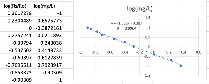
So mg/L = 10 ^ (-1.51log(Rs/Ro)-0.39)
I tried to program but I kept getting this error…
“invalid operands of types ‘int’ and ‘double’ to binary ‘operator^’“…
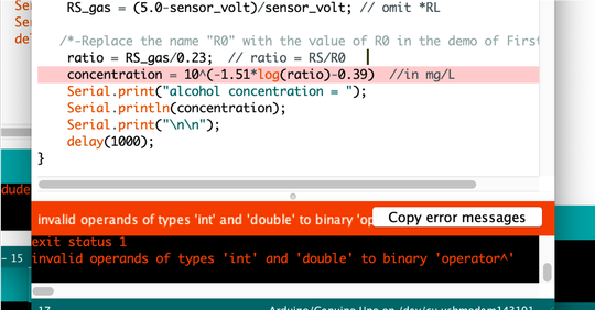
Oh it seems that my problem was with “^”, it should be put into pow().
No error with this code!
void setup()
{
Serial.begin(9600);
}
void loop()
{
float sensor_volt;
float RS_gas; // Get value of RS in a GAS
float ratio; // Get ratio RS_GAS/RS_air
float concentration;
int sensorValue = analogRead(A0);
sensor_volt=(float)sensorValue/1024*5.0;
RS_gas = (5.0-sensor_volt)/sensor_volt; // omit *RL
/*-Replace the name "R0" with the value of R0 in the demo of First Test -*/
ratio = RS_gas/0.23; // ratio = RS/R0
concentration = pow(10,((-1.51)*log10(ratio)-0.39));//in mg/L
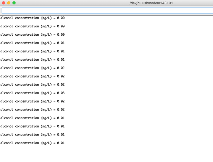
Serial.print("alcohol concentration = ");
Serial.println(concentration);
Serial.print("mg/L");
Serial.print("\n\n");
delay(1000);
}
It seems to work!
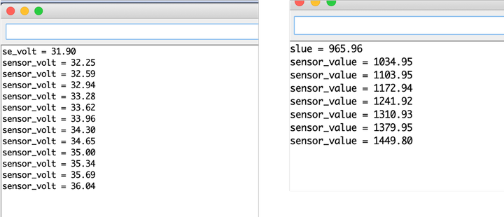
Coding to calculate average value of digital signal
In the previous session, I wasn’t able to retain the average correctly. Here is the part to calculate average:
void setup()
{
   Serial.begin(9600);
}

void loop()
{
    float sensorValue;

    for(int i = 0 ; i < 100 ; i++)
    {
        sensorValue = sensorValue + analogRead(A0);
    }

    sensorValue = sensorValue/100.0;
    Serial.println(sensorValue);
    delay(1000);

}
I consulted the instructors and I figured out that the problems were:
-
sensorValue should be set to 0 every loop.
-
a different variable (sensorAve) should be used to calculate the average.
With this code, I was able to calculate average correctly.
void setup()
{
   Serial.begin(9600);
}
void loop()
{
   float sensorValue = 0;
   float sensorAve;
    for(int i = 0 ; i < 100 ; i++)
    {
        sensorValue = sensorValue + analogRead(A0);
    }
    sensorAve = sensorValue/100;
    Serial.print("sensor_average = ");
    Serial.println(sensorAve);
    delay(1000);
}
Thermistor as heat sensor
I am planning on using thermistor as heat sensor for my final project, so I worked with one.
I’m using it on the distillation tower during operation, so the temperature could go up to 150 Celsius degrees.
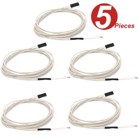
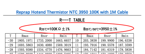
Therefore, I chose one with 100K Ohm. According to its datasheet, it senses heat up to 300 Celsius degrees. It also needs to have long wire so I can keep the controller away from the heat.
I purchased one manufactured by WINGONEER made for 3D printer’s extruder.
How a thermistor works
According to this page, thermistors are variable resistors that change their resistance with temperature. They are classified by the way their resistance responds to temperature changes. In Negative Temperature Coefficient (NTC) thermistors, resistance decreases with an increase in temperature.
Concentration : 0.05 mg/L ~ 10 mg/L Alcohol
Operating Voltage : 5V ±0.1
Current Consumption : 150mA
Operation Temperature : -10°C ~ 70°C
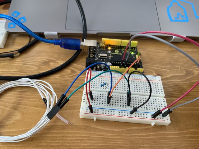
Circuit and program
The circuit is connected as this:

A resistor with a resistance (I chose 100K this time) similar to the thermistor is connected in series with thermistor.
The voltage consumed by thermistor is being output as digital signal.
I connected it to ATTiny44 with a 20MHz resonator. ATTiny44 is connected to FabISP.
The connection of 20MHz resonator is described in week11 (oops, the timeline is a bit mixed up).
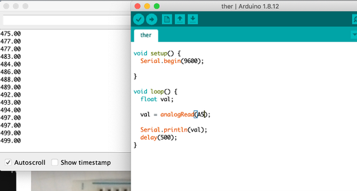
At first, I connected the digital signal to pin 5 and ran this program:
void setup() {
  Serial.begin(9600);

}

void loop() {
  float val;

  val = analogRead(A5);
  Serial.println(val);
  delay(500);
}
I opened Serial Monitor, but found out that the values are not changing when being heated.
I suspected that it’s because pin 5 is also connected to MOSI so that disturbs the signal.
So I re-connected the diginal signal to pin 2 and changed the program to this:
void setup() {
  Serial.begin(9600);

}

void loop() {
  float val;

  val = analogRead(A2);
  Serial.println(val);
  delay(500);
}
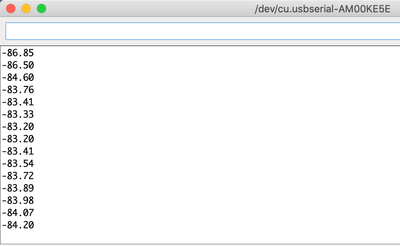
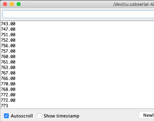
The serial monitor is outputing values that changes according to the temperature this time!

Calibrate the value
Right now the serial monitor is outputing digital signal of voltage.
I refered to this page to transfer the value into actual temperature.
The resistance of a semiconductor follows this equation.
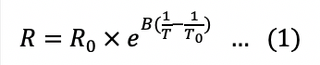
In this equation,
T is the temperature (in kelvin)
R is the resistance at T (in ohms)
B, R0, T0 are constants presented in the datasheet.
Equation (1) can be transformed into equation (2) and (3).
Since B, T0, R0 are all constants, it can be derived that there is a linear relationship between 1/T and lnR.
So I took the data of R (I used Rnor) and T from the data sheet (the copy & paste was too much work so I only took the data from 50-125 degrees celcius), and calculated 1/T(T transformed to kelvin) and lnR on Excel.
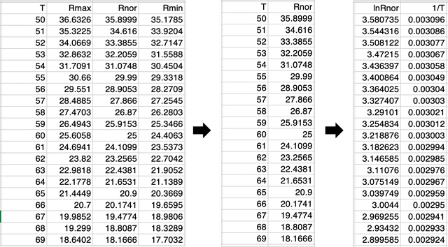
I plotted 1/T and lnR, and derived a trendline.
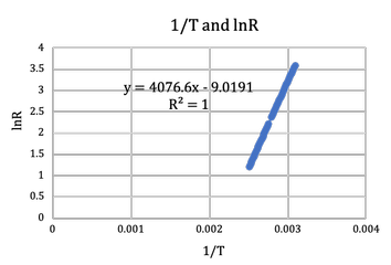
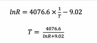
Therefore, we can calculate T from R like this:
R can be calculated as:
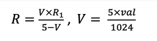
R1 is the 100K Ohm resistor, val is the digital signal read.
So I ran this code,
const float R1 = 100000;

void setup() {
  Serial.begin(9600);

}

void loop() {
  float val,V,R,T;

  val = analogRead(A2);
  V = 5*val/1024;
  R = V*R1/(5-V);

  float y = 4076.6/(log(R)+9.02);

  T=y-273.15;

  Serial.println(T);
  delay(500);
}
But got negative read…
Debugging with Arduino UNO
I started suspecting that it’s the connection and setting of ATTiny44, since the val read seems a bit higher than it should be from the beginning.
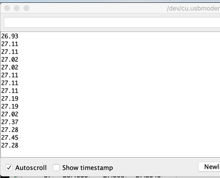
So I tried using Arduino UNO.
The reading seems correct this time.
But when I tried to run the code, I got negative temperature again.
Then I realized, that I didn’t multiply 1000 on the R written on the datasheet.
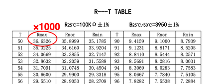
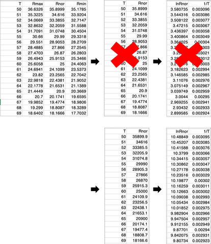
The graph and the trendline seem to change too.
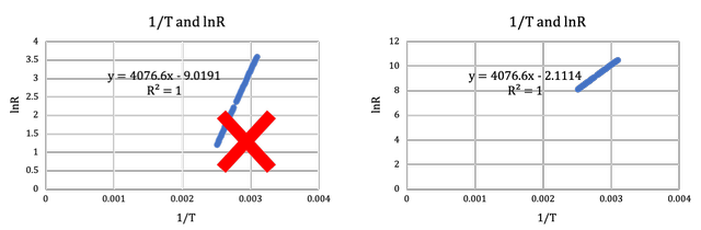
I used the new equation for the trendline and changed the number in the code:
#include <SoftwareSerial.h>


#define TX    0
#define RX    1

const float R1 = 100000;

void setup() {
  Serial.begin(9600);

}

void loop() {
  float val,V,R,T;

  val = analogRead(A2);
  V = 5*val/1024;
  R = V*R1/(5-V);

  float y = 4076.6/(log(R)+2.11);

  T=y-273;

  Serial.println(T);
  delay(500);
}
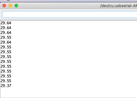
And I got values that seem to be correct!!
Reconnecting with ATTiny44
Now I need to figure out what happended to the connection with ATTiny44…
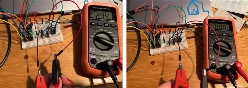
I used a multimeter to debug.
I found that the voltage between the thermistor is 3.91V although it is supposed to be around 2.5V. And when the 100k Ohm resistor is taken away, the voltage is 3.58V although it is supposed to be 0V.
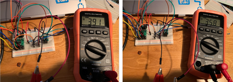
I plugged the signal cable to PA3 instead of PA2.
And the voltage between the thermistor is now 2.44V, and 0V when the 100K Ohm resistor is taken away!!
So I changed the code so the signal goes into PA3 instead.
#include <SoftwareSerial.h>


#define TX    0
#define RX    1

const float R1 = 100000;

void setup() {
  Serial.begin(9600);

}

void loop() {
  float val,V,R,T;

  val = analogRead(A3);
  V = 5*val/1024;
  R = V*R1/(5-V);

  float y = 4076.6/(log(R)+2.11);

  T=y-273;

  Serial.println(T);
  delay(500);
}
And I got some number that seems to be right!!!
I heard from an instructor that the reason why value on PA2 is off is because, pullup might be enabled in PA2’s port settings, and that might lead to the raise in voltage.
I didn’t change anything in the settings, but I will look into the details when I can.
Whoa this whole process took me an entire day, but it was totally worth it.
Board production
For my final project, I designed, produced, and programmed a board with input of thermistor and tactile switches.
For further detail, please refer to my final project - electronics page and final project - programming page.
After week09
I was able to dive deep down into 2 different input devices. Both of the sensors’ resistance change according to the environment, thus changing the voltage between them. And the voltage is output as digital signal.
I was able to read the datasheet of both sensors to calculate the actual value of alcohol concentration and temperature based on the digital signal output.