Final project - design & fabrication
Condense tower - Welding
Rico and I went to weld the condense tower at a welding workshop called FeNEEDS Kamakrura.
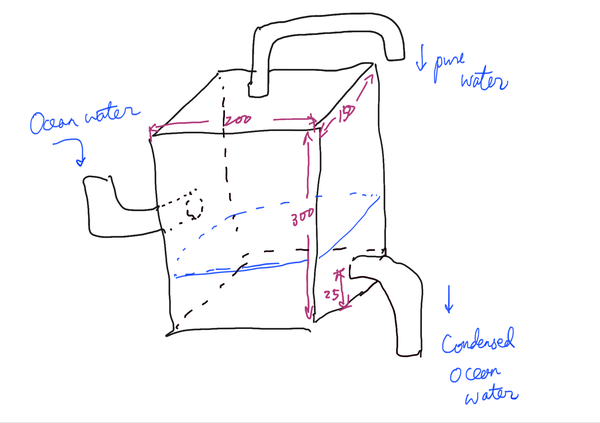
I order 3 stainless steel plate (2 that are 300 * 350 * 1.5mm, and 1 that is 300 * 300 * 1.5mm), and 4 stainless steel pipes (diameter_out = 22mm, thickness = 1mm, length = 500mm) online.
The steel is SUS304. To weld, the thickness needs to be more than 1.0mm.
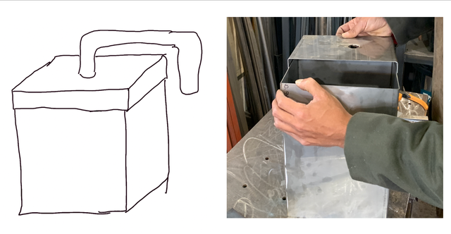
This was the original design.
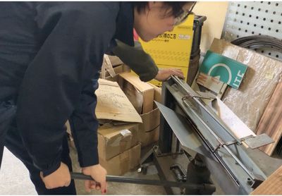
After measuring the materials, we (or the staff) drilled holes on the plates to put pipes in.
A drill with an inner thin mill and an outer 22mm mill (only on the edge) was used. The inner mill was used to firstly drill a hole, and then the outer edge was used while applying oil to avoid overheat.
We used tools to bend the steel and cut the steel.
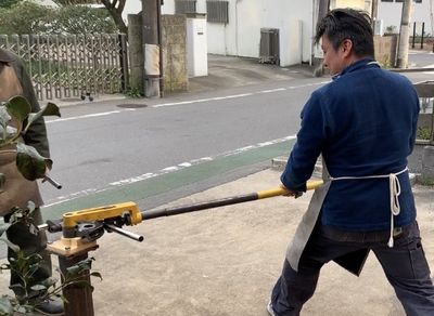
And we got materials like these:
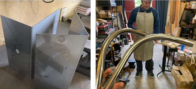
Instead of having a completely sealed box, we decided to make the top a lid. With silicon sealed in between, hopefully it won’t leak any vapor.
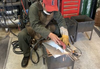
Now it’s welding time!!!
We wore apron, gloves, and a special mask. The mask is very cool, it has light sensor and automatically darkens when it is bright.
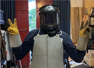
We used an arc welding machine using CO2 gas.
To weld an edge, aim at 1 point for 1 second to make a ball there. Then make another ball that’s touching the previous ball. The concept is to have continuous balls to cover the whole edge. (The video is 4x speeded.)
We welded all the surfaces and the pipes. That was a long journey…
At one point the spark jump to the top of my head and I had to wear a flame-proof cloth. Other than that it was super fun!
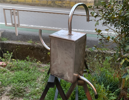
The surface is like this. (After the staff fixing some parts.)
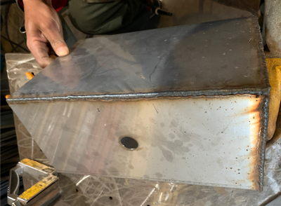
The biggest concern was water leakage. So we did a test and it turned out to be no leakage! (On the left there is the pipe facing down being taped so that doesn’t count.)
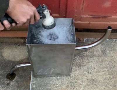
It does look like a weird robot… But I would say it’s a huge success!!
It took us 4 hours, which was a bit exhausting. But I was expecting even longer time, so I’m very happy with the result.
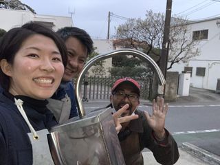
A big thank you to Asada-san (the staff at FeNEEDS Kamakura) and Rico!
Overall, I understood that welding is a process to join metal (that is cut using plasma cutter manually this time) together.
Although this time we used a hand-held plasma cutter, I have also seen online CNC plasma cutter and that is more similar to the digital fabrication methods in a fablab. And welding is like making (assembling) the end product using the material proceeded using digital/analog fabrication techniques/devices.
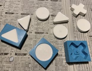
Tactile switch cap - molding and casting
In molding & casting week, I made huge caps to fit onto tactile switches for the buttons.
The details are here.
Peristaltic pump - additive design & fabrication
I designed and 3D printed a peristaltic pump that pumps ocean water into the condense tower by using the motion of a DC 3V-6V TT Motor.
Design
I used Fusion360 to design.
To help me with the dimensions, I downloaded .step file from this site.
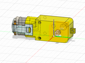
I used Inspect > Measure function in Fusion360 to measure the TT motor.
However, since the model can be different from the actual product, I also measured the motor to confirm.
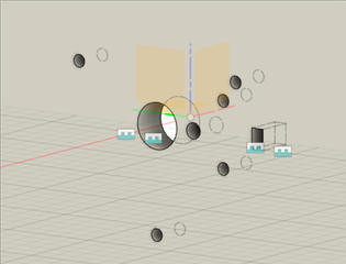
The peristaltic pump consists of 3 parts, the inside that fits onto the axis of motor, 2 exactly same outside parts that hold onto the silicon tube. There 3 are screwed together onto a laser-cut acrylic frame.
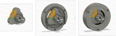
For the inside of the pump, I sketched 3 small circles onto 1 bigger circle, and the center part to fit the motor on, and also to fix onto the acrylic.
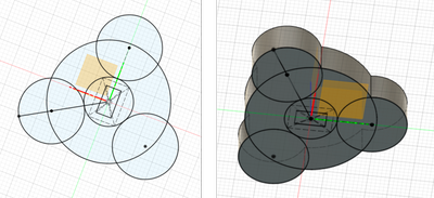
For the outside parts of the pump, I sketched the cross section of it, and revolved it.
I also extruded three holes with a diameter of 3.2mm to let the screws go through.
After mirroring the outside part to make 2, I extruded to make the slot for tube to fit in.
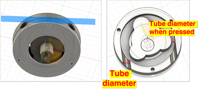
The slot for tube has the dimension of the diameter of tube used.
The distance between the pressing part of the inside part, and the outside part is designed to be the size of tube when being pressed.
I set these 2 as design parameters in case I change the type of tube I use.
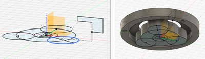
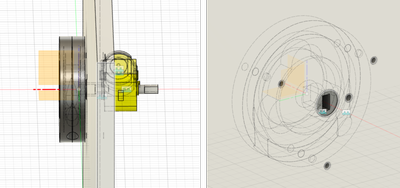
For the acrylic frame, it sits in between the pump and the motor.
There is a hole to fix the center of the inside part of pump onto, and 3 holes to screw the pump on.
To fix the motor onto the acrylic, I made 2 holes to screw the motor on (there are 2 existing screw holes on the motor), and slots to fit on 2 protrusions on the motor.
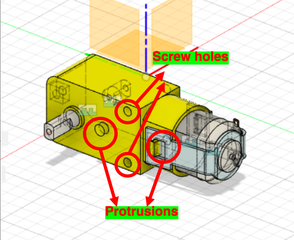
I originally designed a 3D printed holder that screws onto the acrylic. But it turned out unnecessary since screwing the motor onto the acrylic using the exsiting 2 holes is already enough.
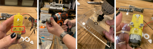
Fabrication
I used Afinia H400+ to fabricate the pump. ABS was used without support.
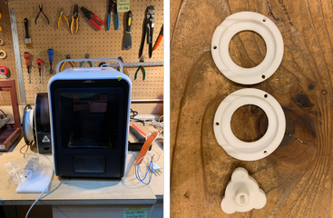
I used Trotec Speedy 100 to cut 5mm acrylic.
I used a driver to make space on the acrylic so flat head screw can be used without sticking out. This is because the pump needs to be fixed onto the acrylic on the other side.
Assembly
When I connected the motor with 6V battery case, the motor didn’t move.
I thought it is because the fiction among the 3 parts of the pump was too big.
So I applied Vaseline as lubricant to the green areas on the illustration.
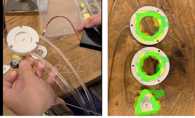
And it worked!
However, later on when I tested it again, it seems that after I stopped the motor, the water still dripped out from the tube. This results from capillary action.
It means that the inner part is not pressing the tube enough. Ideally it should press the tube so there is no space created, thus no water coming out.
Therefore, in 2nd spiral, I would created a bigger inner part of the tube.
Also, instead of Vaseline, I would consider using bearings that generate smoother rolling.
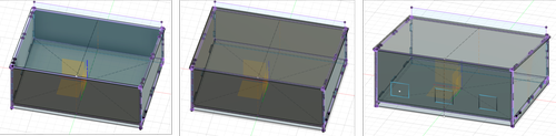
Control panel - subtractive design & fabrication
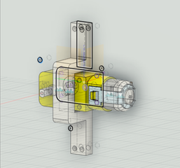
This is the layout of control panel.
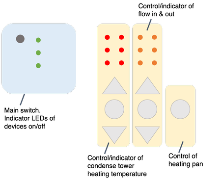
It is divided into 2 areas.
The blue area is the main switch, and the indicator LEDs for devices’ on/off.
The yellow area is the control area. It is laid out so users follow the order of left to right to setup the control parameters. (First set up and start the heating of condense tower, then set up and start the flow in and flow out, and then start the heating pan for condense ocean water.)
The indicator LEDs in the yellow area are lined vertically so they visualize the rise and decrease of each parameter in a more intuitive manner. (When teperature goes up, more LEDs light up vertically.)
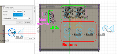
Design
I used Fusion360 to design the press-fit control panel.
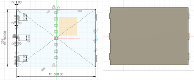
I sketched the bottom with 6 tabs to press fit. Since I used 4mm MDF, the tab’s width was set as 4mm.
I used the outer surface of the bottom press fit tab as the sketch plane of side piece.
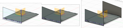
For the back and front piece, I used the surface of edge of bottom piece as the sketch plane.
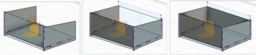
For the top piece, I used the top edge of the side piece as the sketch plane.
To add slots to install buttons, I inserted the dxf file of the tact switch cap I made for molding and casting.
Since I wanted to make the slot slightly bigger than the actual button, I used Sketch Scale in Modify.
I scaled each the circle and the triangle to 1.02 times.
I added circles as slots for LEDs. Since the LEDs I’m using has a diameter of 5mm, the circles I made have diameter of 5.55mm.
I also added 1 circle to put the main switch in.
I individually projected each part onto an offset plane and saved them as .dxf file.
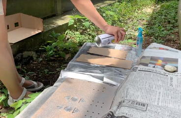
Fabrication
I used Trotec Speedy 100 to cut 4mm MDF.
After cutting, I used a spray paint with silver color to color the panels.
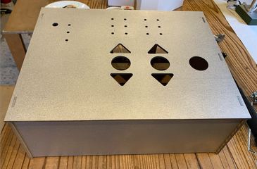
I put the cut pieces all onto used newspaper, sprayed while keeping the spray some distance from the pieces since this helps avoid uneven paint. After spraying once, I waited for it to dry and sprayed second time.
Tadaaaa
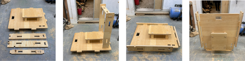
Trolley - subtractive design & fabrication
In computer controlled machining week, I made a trolley to put MINI SALT FACTORY on using CNC.
The details are here.
Files
Peristaltic pump
- Peristaltic pump .step file