7. Computer controlled machining
- Group assignment
- test runout, alignment, speeds, feeds, and toolpaths for your machine
- Individual assignment
- make (design+mill+assemble) something big
Group Assignment
Check out the group assignment page here.
Machine
This week we visited FabLab Hamamatsu to use their CNC Router ZN1325.
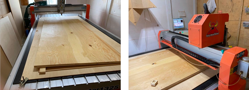
It works for engraving/cutting all types of wood, plastic, PVC board, diabond or non-ferrous metals. Working area is 1300 x 2500 x 200mm.
Design
I wanted to make a trolley for my final project to carry the distillation tower.
Yes, I want a trolley to carry the whole thing.
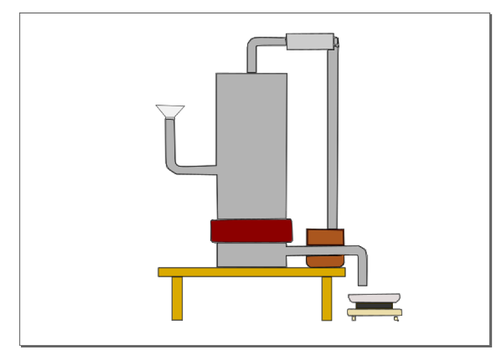
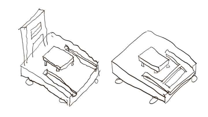
The trolley would have a small table to put the tower itself, creating the height for fluid flow.
I also wanted the trolley to be easily carriable, so preferably foldable.
Through multiple trial and error, I figured some manners of design for CNC machine.
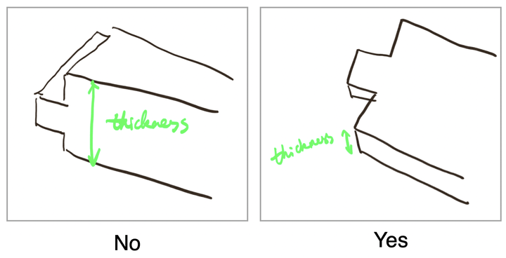
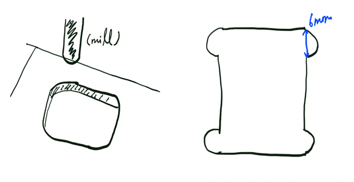
Firstly, when creating a joint, since the machine can only cut from one side, the inserting part should be created by cutting the surface vertically not horizontally.
Then I experimented with methods to fold the handle or to store the handle onto the bottom.
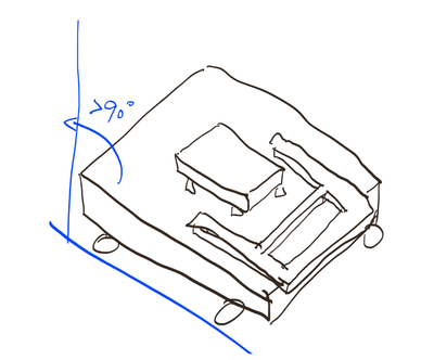
The first plan was to have trenches on the bottom, so the handle can slide in there.
However the problem is, when tilted over 90 degrees, the handle might fall off the bottom.
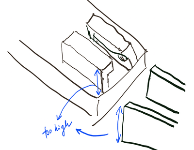
The second plan was to build a holder at the end of the bottom, so the handle can slide in.
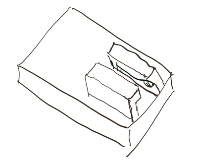
The problem is, to ensure the stableness, I was thinking about making the handle wider. Thus the sliding part would be too tall and it is not compact enough.
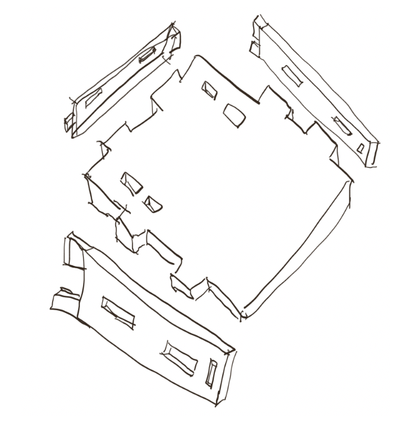
The third plan was to take the handle apart, and fit all 3 parts onto different sides of the bottom.
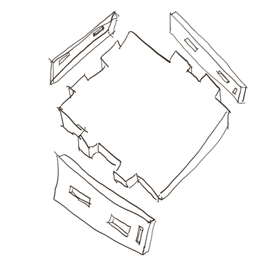
This seems to be the most feasible plan so I went with this one.
The joints were planned to be like this:
To make the joints easier to fit, I added dog bones to each hole. (Then I realized that I also needed to create those for the inserting parts, but that was too late.)
This is because, since the mill’s shape is rounded, it wouldn’t create perfect 90 degrees, so even if the model is rectangle, the corners would be rounded. The dog bones ensure that the holes are not smaller than the inserting parts.
Since the mill I’m using was 6mm in diameter, I added 4 half circles with a diameter of 6mm on each edge of the rectangular holes.
Model
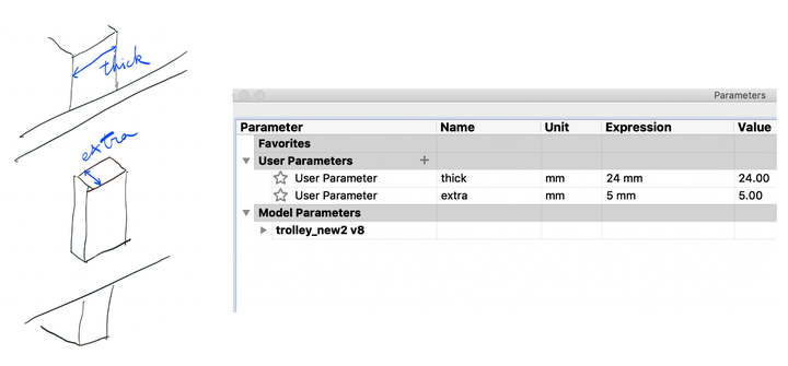
I decided to use a material that has a thickness of 24mm. But I still used parametric design in case I decided to change the material.
I set up these parameters. “thick” is the thickness of the material, “extra” is how much the inserting part is coming out of the hole to ensure a better fit.
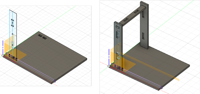
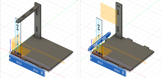
I started with drawinng and extruding the bottom, with 4 holes to instert the vertical beam of the handle.
From the plane of inner side of the holes, I drew and extuded the 2 vertical beams. And from the 2 vertical beams, I created the horizontal beam.
I aligned the beams to the edge of the bottom to create the inserting parts on the bottom.
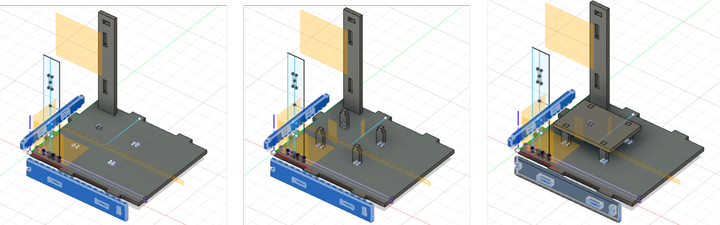
I made holes on the bottom, added feet to the small table, and added the table top.
To create .dxf file for CNC machine, I sketched the wood I was going to use, and aligned all the parts on the XY surface.
Then I created an offset plane above those, and projected all the parts onto the plane.
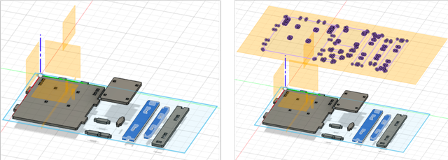
I selected the sketch on the offset plane, and exported it as .dxf file.
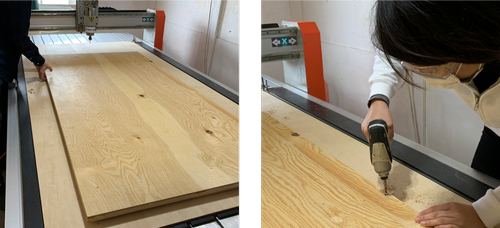
Set up
I put the wood onto the sacrificial wood, and screwed it through the sacrificial wood onto the base wood. (According to the instructor, “there are 2 main purpose of the sacrificial wood, 1) something to fix your actual material to (by screwing into it), so the actual material can be kept flat and unable to move while being milled. 2) something to prevent the endmill from drilling into the metal surface of the CNC machine bed”.)
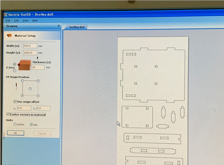
I opened my .dxf file, put in the dimension of the wood material, and selected “center vectors in material”.
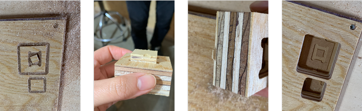
Before actually cutting the boards, I tested the joints with dog bones.
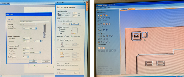
The set up was:
- Cut depth - 24.5mm (deeper than the wood’s actual dimension to ensure it is cut properly)
- Pass depth - 6mm (I didn’t know you should keep the depth in between half to 1 time of the mill’s diameter)
- Machine vectors - outside
- Spindle speed - 12000rpm
- Feed rate - 700mm/min
- Plunge rate - 300mm/min
- Tab length - 5.0mm
- Thickness - 4.0mm
The parts were nicely cut! And the 2 parts fit.
However, the tabs were too small that one broke before I applied any force.
And the cut went pretty deep into the sacrificial wood.
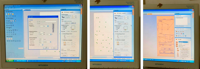
So I decided to set the cut depth to 24.2mm, increased tab thickness to 6mm, increased tab length to 7mm, and added more tabs.
I also changed pass depth to 5mm, and I added some more tabs.
My understanding is that, since we are doing 2D cut not super fine 2.5D shapes, the speed, feed rate, etc. wouldn’t effect the finish much. However, feed rate too high or spindle speed to high could cause the mill to bend. A sweet spot needs to be found to ensure shorter cutting time and also safe milling.
Generate toolpaths
“Cut2D” was used to generate toolpaths.
After opening the .dxf file on Cut2D, I set the parameters as stated above, added tabs, and was able to generate toolpaths.
Cut
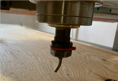
Unfortunately, I bent the mill while cutting…
I paused the machine when cutting to confirm the cut, and I restarted by pressing the button.
However, since the machine follows the gcode, it only starts the spindle at the beginning of the project. Thus in the middle of a project, it wouldn’t restart the spindle before cutting and that’s why it bent.
If you pause the cutting, remember always restart the spindle first before you restart the project.
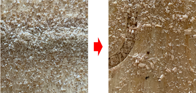
When cutting, instructor Take-san taught me to tell if the speed is appropriate by looking at the sawdust.
At first, my sawdust was very fine, which means I could raise the speed to have more coarse sawdust.
(Fine milling with fine sawdust generated is ok, but since I’m only cutting 2D and not expecting a perfect finish, coarser milling with coarser sawdust is enough.)
The left is with 70% of feed rate, and right is with 150% of feed rate.
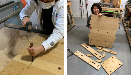
I took the parts off the wood, cleaned the sawdust, and got my parts.
Safety measures
These are the safety measures to pay attention to during the process (with a reference to this site):
-
Always wear protective gear including eye and ear protection and closed toe shoes. Avoid loosely fitting clothing or dangling jewelry.
-
Keep eyes, hands, hair and clothing away from the ShopBot and router while it is operating. Tie long hair back. Do not use your hands to hold down parts that may come loose as they are cut out.
-
Listen for changes in sound that may indicate a problem while running the tool. ALWAYS be near enough to be able to stop the ShopBot should a problem arise (lift the shield or press stop to stop).
-
You must have yourself (the operator) and one other person on site for safety at all times.
Assemble
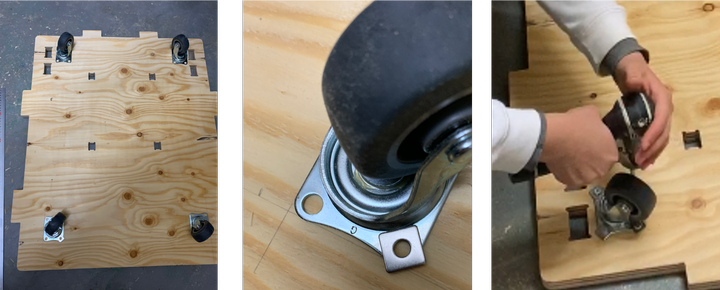
I screwed the wheels onto the bottom with washers in between screws and wheels.
When assembling, the joints seemed a bit too tight. I wanted them to be able to connect/disconnect without having to use a hammer every time.
To make the inserting parts smaller, and all the surfaces smaller, I applied file and sandpaper onto the parts manually at first, and used some machines too.
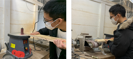
Another thing is that, I should have added dog bones onto the inserting parts too. So I sanded the material to create some. Basically make the vertical angles to acute angles.
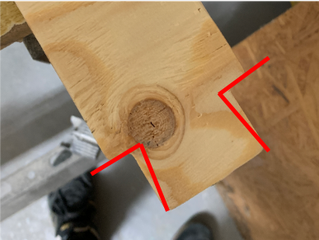
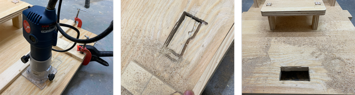
I wanted to add a hole on the bottom as a handle when carrying the trolley by hands.
I used a router. It is not very stable when turned on, so wood blocks were used to help guide the path.
After failing many times on moving the mill in a straight line along the guided paths made with wood blocks, I managed to make a handle!
Tadadada…
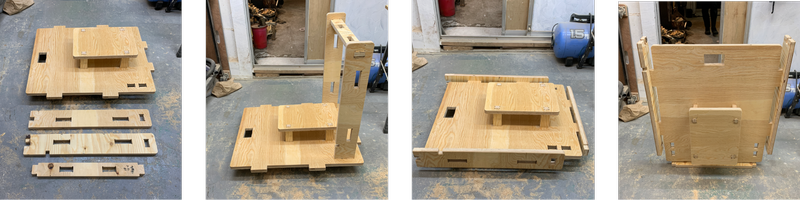
How the trolley can be portable:
How the trolley carries people:
After week07
-
When building the model, I spent 5 hours on discovering the rules for designing, while the actual designing process was only 1 hour. Through trial and error, I learned a lot about the potential and constraints of CNC machines. It was definitely very precious experience.
- The potential is that you can choose the cut speed based on the finish you want, and it is cut pretty precisely so as long as the parameters are well set, the parts fit perfectly.
- On the other hand, the cutting parameters need to be set correctly so the parts can fit. It can’t cut 90 degrees angle, and kerf needs to be taken into consideration.
-
Wow the wood was so much heavier than I thought… I wanted to carry it back by hands but was almost impossible… It would be great to consider combining different materials next time. Carbon fiber…?!!!