5. 3D Scanning and printing
Assignments
- group assignment:
- test the design rules for your 3D printer(s)
- individual assignment:
- design and 3D print an object (small, few cm3, limited by printer time) that could not be made subtractively
- 3D scan an object (and optionally print it)
Group assignment
The group assignment is documented here.
Below is the same as what I documented there.
I tested the design rules for Afinia H400+.
Since I wanted to make a ball shaped structure with skeletons, I used existing design data to test dimensions and wall thickness, and designed data of a structure to test how thin can it go to build a 90 degrees overhang.
Testing wall thickness
I started with wall thickness. The stl data is downloaded from here.
After connecting the printer to the laptop, I opened AFINIA 3D software, and opened the stl data.
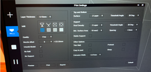
I set the layer thickness as 0.15mm, and selected the filling rate as the image below. And it showed the preview and the printing time (54 minutes).
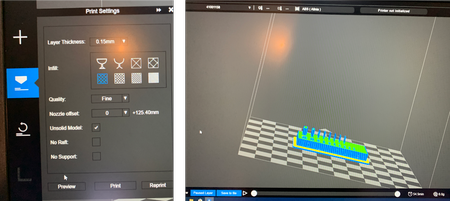
I added raft and disabled support since the concept is to test the performance without support.
Before starting the printing, I preheated the printing bed. For other printers, when you start printing, it usually heats up the bed, then the nozzle to 270 degrees C, then start printing. However, for AFINIA H400+, it starts printing once it heats up the nozzle without much attention to the bed. If the bed is not heated enough, it might cause the printed item to bend especially when it has bigger bottom area.
After pressing the pre-heat button and set the time to 60min, you can obeserve the bed temperature raising on the top of the interface.
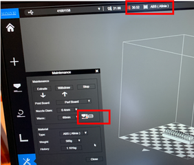
I started printing once it reached approximately 50 degrees C.
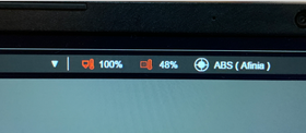
Once started, the temperature’s unit turns to percentage. 100% is 100 degree C so 48% represents 48 degrees C.
This is how it is printed:
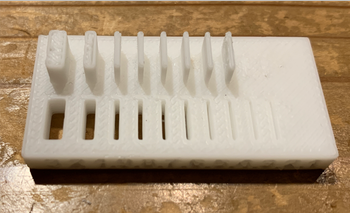
As seen in the printed item, this printer with this setting can print slit down to 0.5mm (0.3 & 0.4 still recognisable, but not cut through), and a wall down to 0.5mm.
Testing dimensions
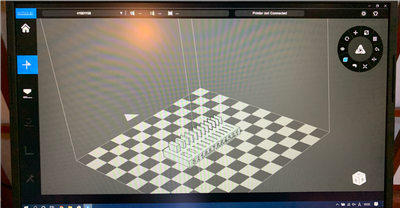
I also printed the dimentions calibration structure. The stl file is here.
I set up the 3D printer as before, and printed the structure.
It turned out to be like this:
I used a caliper to measure the inside and outside of the structure.
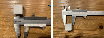
The inside was 9.9mm while the outside was 19.95mm. They were set to be 10mm and 20mm so the difference is the error of this printer.
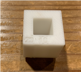
Testing overhang
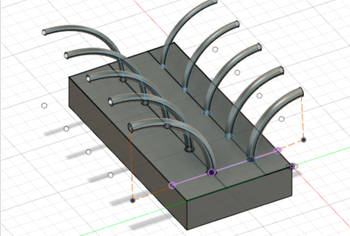
This test is to see down to what thickness can the printer handle an 90 dgrees arc.
Creating 3D data
I created 3D data for a structure to test overhang of different thickness.
I firstly drew the base and the arcs’ basis with a range of diameters from 3.3 to 2.1mm with 0.3mm difference each. There were 2 rows because one is for an arc with radius of 20mm and the other of 30mm.
Then I drew arcs from the center of each circle. There radius of arc are 20mm and 30mm of different rows.
I used “sweep” feature from “create”.
Type > Single Path
Profile > the circle on the base
Path > the arc
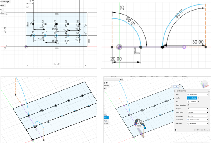
After extruding the basis, the model is built!
I used the same settings for the printer and it’s printed like this:
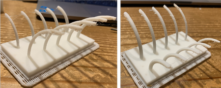
From the picture on the left, it can be seen that all of those made into arc with 30mm radius has some unstable structure, while the 20mm arcs on the right showed better performance - 3.3mm seems stable, 3.0mm rather stable, but some unstable structure for diameters under 2.7mm.
Individual assignment
Trying to make spiral along a sphere
At first I wanted to make a shape like this - sprials that grow along a sphere.
I heard from Kai-san that it’s way easier to make with Grasshopper than Fusion 360, but Rico discovered this tutorial so I decided to give it a try using some of the technique from the tutorial on Fusion 360.
I created a sphere, and defined a plane that touches the bottom of it.
From that plane, I created a triangular(internal) shaped coil that cuts the sphere.
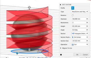
Go to sketch (any plane seems to be ok), Project > Include 3D geometry, select a spiral that’s on the geometry, disable body, and I got a spiral.
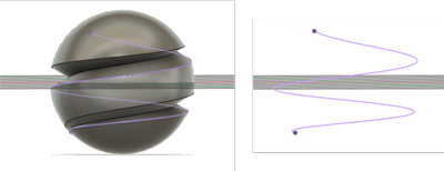
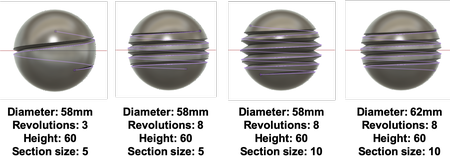
There seems to be several factors that decide the shape of the spiral: Diameter, Revolution, height, and section size. I played around with them and got different shapes of sprial.
I thought I could find a set of parameter which creates a spiral that goes to the top point of the sphere but it seems hard. So I decided to leave it like this.
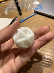
Making a sphere structure inside another sphere structure
I first made a circular pipe with a diameter of 4mm, used circular pattern to copy the shape around it.
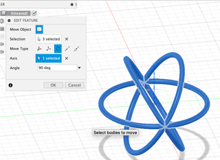
Then copied and rotated some more. And I copied the shape, used Scale function to shrink it to 80%.
I moved the smaller one into the large one.
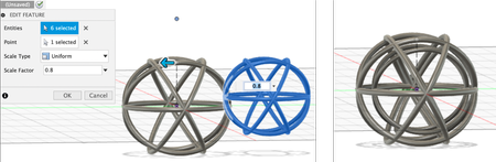
Then resized it a bit so the bigger one has a diameter of 20mm, while the size of the pipe still remains 4mm in diameter.
I printed the geometry with AFINIA H400+ with support. After printing, I tried to get rid of the support, only to find that in the horizontal direction, the 2 rings are basically attached to each other…
So I decided to make a bigger geometry.
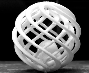
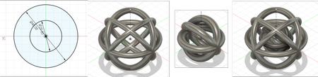
This time I drew the 2 spheres separated instead of copying. The outer one has a diameter of 40mm, and the inner one is 20mm. I made a geometry with intervening pipes for the outer one with a diameter of 4mm, and then for the inner one with a diameter of 4mm too. The structure is simpler inside than the outside.
I printed it with support, but the least possible.
However, I still got a LOT of support, it took me more than 30 minutes to get rid of, it generated a lot of waste, and it’s almost impossible to get rid of everything…
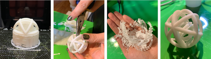
The sphere inside is able to move without constraints, so I guess it is a success?
Then I tried to print without support.
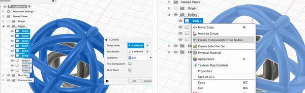
I made the data on Fusion 360 using joints so the 2 spheres are attached to each other on 1 point.
The rings were separated as individual bodies. So I combined bodies on the same sphere into one body. And I made components out of the bodies.
I ended up with 2 components - the bigger sphere and smaller sphere.
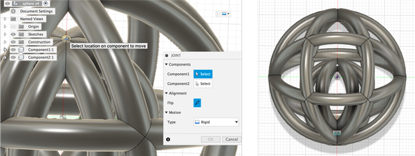
I used joint to attach the bottom of smaller sphere to the inner bottom of the bigger sphere. And I got the model!
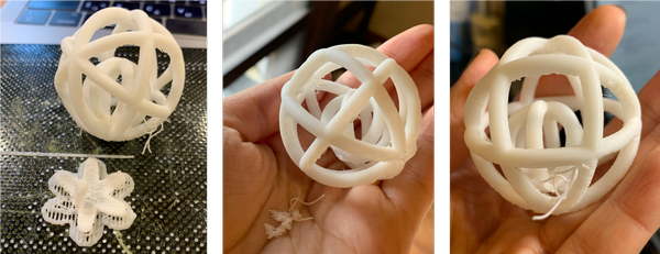
I printed with raft, without support, and the structure being slightly moved upwards.
The printing time was 1hr37min, 20 minutes shorter than the one with support.
There was so much less waste! The form was a little bit uglier than the one with support but I think it is enough for a prototype.
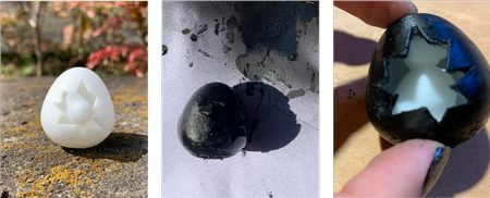
Making a duck inside an egg
I have this other idea of a duck inside an egg with a hole on the eggshell so you can see the duck from the outside. The duck is bigger than the hole, so you can’t just make the duck and eggshell indivisually and put the duck inside. Thus it can’t be made by subtractive process but only with an additive process.
I tried “create form” mode of Fusion 360 for almost the first time.
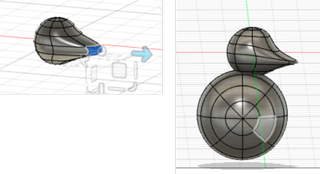
I firstly made 2 spheres attached to each other, I used the modify feature to move the lines and dots and surface to create shape.
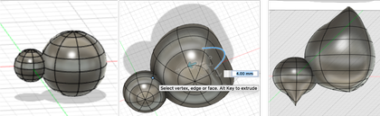
It seems to be ok, however when I tried to finish form, I got many errors. As you can see, some points and lines are not smooth, and some dots are not connected to each other.
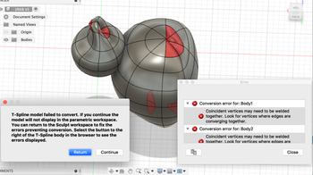
I tried to only move surfaces and not move points or lines. This time it seems a lot smoother and I was able to finish form without any errors.
Then I drew the cross session of egg shell, rotate to make the egg shell, drew a shape on the plane touching the egg that represents the crack on the egg, and extruded it.
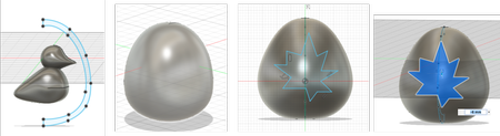
The egg is successfully made!
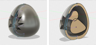
I printed it with the least support as the previous one. I tried to get rid of the support with pliers, and applied some acetone to the bottom of the duck. I can’t say that the support is completely gotten rid of, but the duck is free to rotate inside!
Here is a shot with the beautiful nature of Kamakura with its head sticking out, and a shot of it after its shell being painted black (I stuck some tissue in when painting to protect the duck).
3D scanning
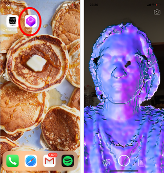
I tried Capture - a 3D scan app installed on my iPhone X.
It uses Apple’s TrueDepth front-facing camera system which is also used for FaceID (a substitute for TouchID to unlock iPhone).
According to this page,
TrueDepth starts with a traditional 7MP front-facing “selfie” camera. It adds an infrared emitter that projects over 30,000 dots in a known pattern onto the user’s face. Those dots are then photographed by a dedicated infrared camera for analysis. There is a proximity sensor, presumably so that the system knows when a user is close enough to activate. An ambient light sensor helps the system set output light levels.
Apple also calls out a Flood Illuminator. It hasn’t said explicitly what it is for, but it would make sense that in low light flood-filling the scene with IR would help the system get an image of the user’s face to complement the depth map — which explains how Apple says it will work in the dark. IR also does an excellent job of picking up sub-surface features from skin, which might also be helpful in making sure masks can’t fool the system.
Wow… This is impressive!
However, the scanning process was a bit complicated since I have to go around the object I’m scanning with the selfie camera facing it.
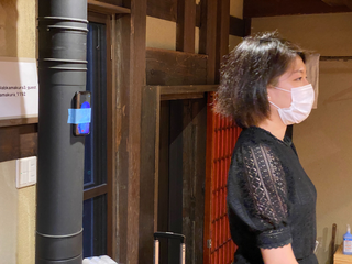
So I taped my iPhone to a pillar in the lab, in order to scan myself.
After pressing start (the round button on the screen), I made a 360 degrees turn slowly, making sure my position stayed the same.
This is the result! The top of my head is missing…
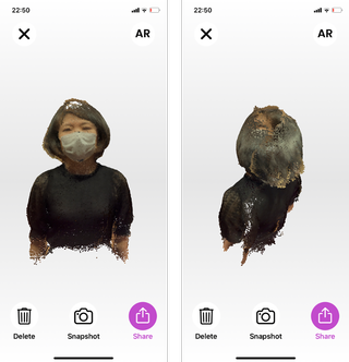
I think if I wanted to fill out the top of my head, what I should have done is: after scanning at the height of my face, move the camera up to scan the top of my head.
The operation seems complicated but could be possible if I had someone else’s assistance.
The file it generates is .usdz.
According to this page,
USDZ stands for Universal Scene Description. It is a file format for 3D models, introduced by Apple in collaboration with Pixar for its ARKit.
I’m not very familiar with AR technology, but was thinking how I can get this file into stl to open on Fusion360.
I searched for ways to convert usdz file to stl but didn’t get any good results.
But I found another app called Scandy Pro that exports your scan file as OBJ, STL, etc.
The scanning process is the same as Capture, and you can export the file after the scanning.
This time I only scanned the front of me by moving my arm around my head.
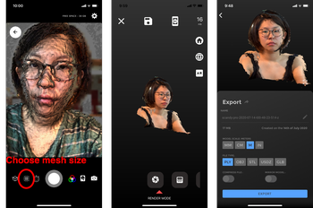
However, with the free plan, you can only do 1 scan per day.
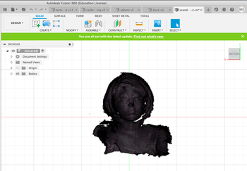
And I was able to open the .stl file on Fusion 360.
After week05
-
Before I only knew how to print things on a 3D printer with the default setting, but after this week, I learned a lot about the potential of 3D printer - whether it’s about the possibility of additive design, and how you can design your data based on the constraints of the machine. I would love to try out Cura next week to explore more.
-
The advantage of 3D printing is the flexibility of what you can make. And since it is not so expensive, individuals can own them to make things they need even in their household. The disadvantages are the time consuming aspect, and the lack of preciseness aspect of it. So if you need a large amount of a same object, or you need something that fits a dimension precisely, 3D printing might not be a good choice (well you can calculate the error by testing and calibrate the model to create the precise size, but that can be even more time consuming).
-
I was astonished by how fast you can 3D scan something. The preciseness could be a concern (might be more precise if I did it with more care?) but you can fix the parts by editing the 3D scanned file. I can see it being used in AR industry, and also benefiting art preservation (scanning art and preserving the data), health care (to make artificial body parts that fit someone perfectly), and so on.
Files
-
Testing tool for overhang .f3d file
-
Testing tool for overhang .stl file
-
Sphere in a sphere .f3d file
-
Sphere in a sphere .stl file
-
Duck .f3d file
-
Duck .stl file
-
3D scanning data .stl file
I hosted it on Sketchfab since the file was too big (26MB).