Final project - electronics
Heating control of condense tower
Thermistor as heat sensor
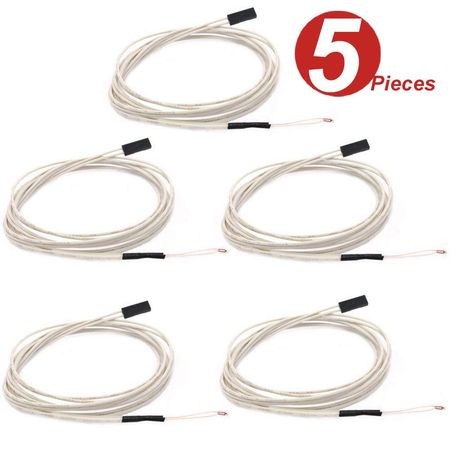
I am planning on using thermistor as heat sensor for my final project, so I worked with one.
I’m using it on the distillation tower during operation, so the temperature could go up to 150 Celsius degrees. It also needs to have long wire so I can keep the controller away from the heat.
Therefore, I chose one with 100K Ohm. According to its datasheet, it senses heat up to 300 Celsius degrees. It also needs to have long wire so I can keep the controller away from the heat.
I purchased one manufactured by WINGONEER made for 3D printer’s extruder.
The details can be found in week09’s documentation.
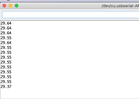
But after a lot of effort, I was able to output the temperature in Celsius degrees.
SSR controlled heater
I used a feedback system with thermistor as heat sensor to control the heating.
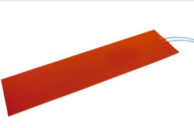
With heating, I tried to use a silicone band heater (SAM0330 by Sakaguchi dennetsu) for the heating system of the distillation tower.
It’s sized 30mm×300mm, with 90W power under 100V.
I want to use a solid state relay (SSR) to control it.
According to wikipedia,
A solid-state relay (SSR) is an electronic switching device that switches on or off when a small external voltage is applied across its control terminals. SSRs consist of a sensor which responds to an appropriate input (control signal), a solid-state electronic switching device which switches power to the load circuitry, and a coupling mechanism to enable the control signal to activate this switch without mechanical parts. The relay may be designed to switch either AC or DC to the load. It serves the same function as an electromechanical relay, but has no moving parts.
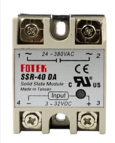
I used SSR-40 DA by FOTEK (datasheet) with 40A current output.
I will use my 5V board to control the on and off of the heater using SSR.
The idea is,
when I set the target temperature in the program,
thermistor monitors the temperature,
the heater is on when it is below the temperature, turned off when it’s over, and on again when it’s below.
Program
Turning relay on and off
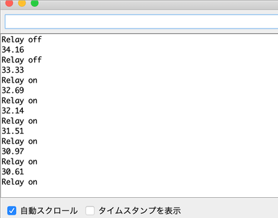
I firstly refered to this video and did a simple program so the relay turns on when it’s below 32 degrees, and off when its over.
I combined the code I created to sense temperature using thermistor. The details are here.
const float R1 = 100000;

int relayPin = 8;// set pin 8 for relay output

void setup() {
  Serial.begin(9600);
  pinMode(relayPin, OUTPUT);


}

void loop() {
  float val,V,R,T;

  val = analogRead(A3);
  V = 5*val/1024;
  R = V*R1/(5-V);

  float y = 4076.6/(log(R)+2.11);

  T=y-273;

  Serial.println(T);


if (T < 32) {

digitalWrite(relayPin, HIGH);// set relay pin to HIGH
  Serial.println("Relay ON ");

} else {
 digitalWrite(relayPin, HIGH);// set relay pin to HIGH
  Serial.println("Relay OFF ");
}
  delay(1000);
}
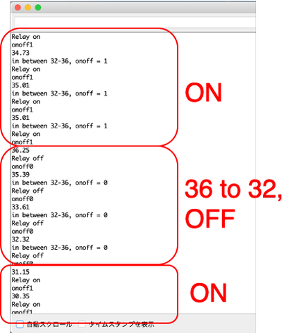
Implemenet hysteresis control method
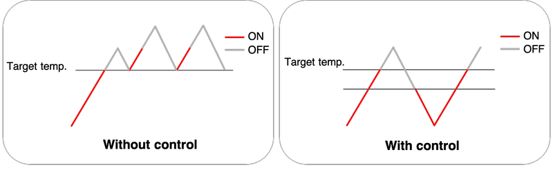
Without control, it would start heating every time when it drops to the target temperature, so it will always be over heating.
With hysterisis control method, th heater it only turns back on again when the temperature drops to a temperature that is below the target temperature.
I divided the cases by temperature.
When the target temperature is 36,
-
when it is over 36, the relay turns off, function “onoff” set to 0
-
when it is 32-36, and when “onoff” is 1, it means the temperature is rising. So keep the relay on, and set “onoff” to 1.
-
when it is 32-36, and when “onoff” is 0, it means the temperature is dropping. So keep the relay on, and set “onoff” to 1.
-
when it is below 32, the relay turns on, function “onoff” set to 1.
Here is my code.
I had an issue where I used if (onoff = 1) instead of if (onoff == 1). ”=” is always for substitution while “==” is for comparison.
const float R1 = 100000;

int relayPin = 8;// set pin 8 for relay output
int onoff;

void setup() {
  Serial.begin(9600);
  pinMode(relayPin, OUTPUT);


}

void loop() {
  float val,V,R,T;

  val = analogRead(A3);
  V = 5*val/1024;
  R = V*R1/(5-V);

float y = 4076.6/(log(R)+2.11);

  T=y-273;

  Serial.println(T);

  if (T < 48) {
  digitalWrite(relayPin, HIGH);// set relay pin to HIGH
  Serial.println("Relay on ");
  onoff = 1;
  } else if (T < 50) {
    if (onoff == 1){
    digitalWrite(relayPin, HIGH);// set relay pin to HIGH
    Serial.println("Relay on ");
     onoff = 1;
    } else {
    digitalWrite(relayPin, LOW);
    Serial.println("Relay off ");
    onoff = 0;
    }
  } else {
   digitalWrite(relayPin, LOW);
  Serial.println("Relay off ");
  onoff = 0;
  }
 Serial.print("onoff");
   Serial.println(onoff);
  delay(2000);
}
It worked well!
Set up hardware
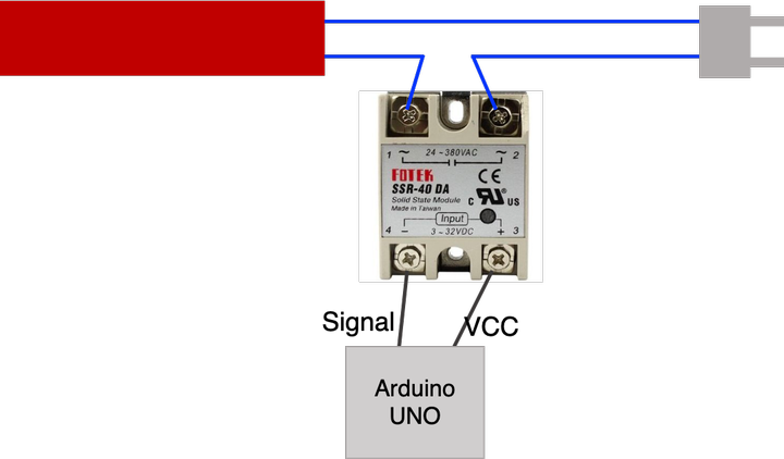
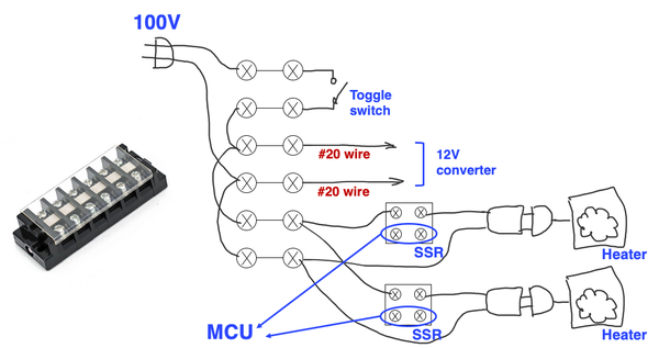
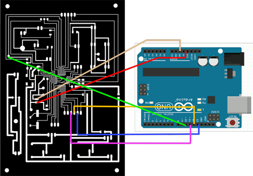
The circuit is supposed to be connected in this manner.
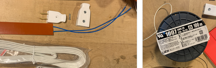
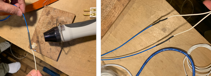
The wire for heater is too short (it will get hot so you don’t want to put the control system right next to it), so I extended it by soldering AWG20 wire onto it.
There are wires with names like AWG20, AWG26, … The smaller number, the more current it can let go through.
AWG26 is usually used for jumper wires.
Heat shrinking tubing is put onto the wire before soldering, so afterwards it covers up the part with metal exposed. (You don’t want to accidentally touch the metal part later, so the tube is for insulation.)
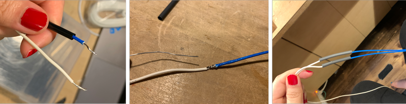
Then I used a heatgun to heat the tube, and the tube shrinks to fit the wire.
I opened a plug, and screwed both the wires into it.
The wires should be installed the same direction as the screw is screwed in.
Be careful not let the 2 cables touch each other. This goes up to 100V so a shortage would be very dangerous.
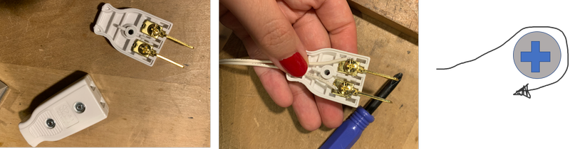
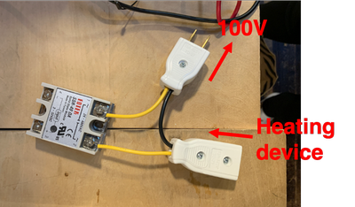
Then I plugged it onto the SSR40 prepared by Yamamoto-san with plugs.
One plug goes into 100V, the other is to accept heating device.
I then connected the other side of SSR to Arduino UNO (+ to 5V, and - to pin 8 for signal).
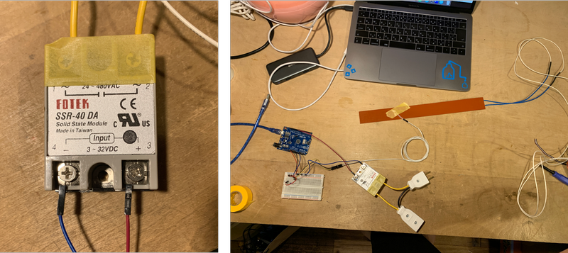
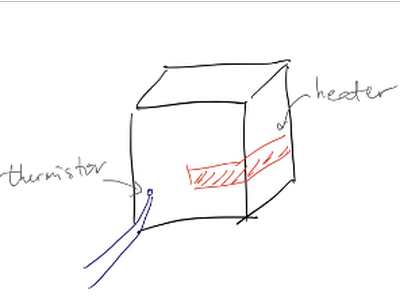
I set 50 as the target temperature, taped thermistor onto the heater, and a tester with heat coupler to make sure that the read is correct.
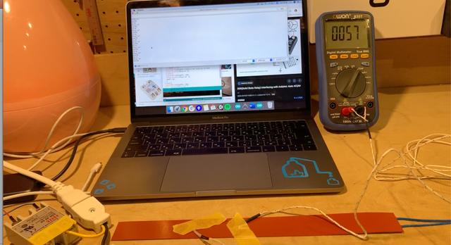
The control works fine, and the temperature read from the thermistor is almost the same as tester.
Then I taped the heater onto my distillation tower.
I decided to tape it vertically not wrapping around the tower, since this creates more contact surface area.
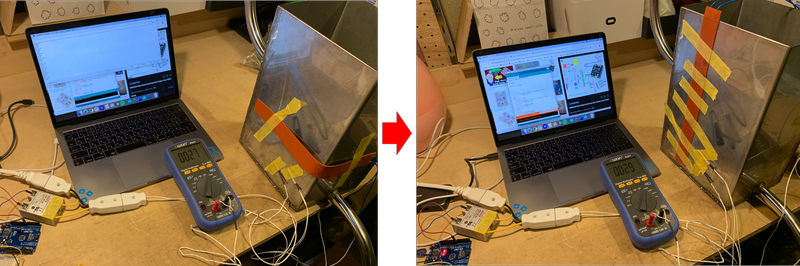
I found that the read of tester’s read being higher than that of the thermistor. (When tester was 56, thermistor was 45)
This is because it is taped higher than the termistor, and since the upper side has less material to heat up (the lower side has the bottom to heat up).
My problem was that, the heating takes sooo much time, and after 3 minutes, when the side with heater taped onto hits 60 degrees, the back was still room temperature…
Band heater was just not strong enough for what you need for the project. So I used electric stove instead. All worked the same, the only difference is to plug the stove’s plug onto the SSR instead of band heater and all worked fine.
LEDs matrix on the control panel
I was planning on controling 12 LEDs using digital pins of ATMega328.
But since the number of pins I can use are limited (12 digital pins in total on ATMega328), I used LED matrix.
According to this page,
“An LED matrix is another way of connecting multiple LEDs together, reducing the number of digital pins required to drive the display.”
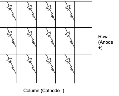
In my matrix for 12 of the LEDs, there are 3 rows connected to the anodes of LED, 4 columns connected to the resistors connected to the cathodes of LED.
Each row and column is connected to 1 digital pin, so 7 pins are used instead of 12.
Only the LED that has its row’s pin written high, and its column’s pin written low will light up.
Program
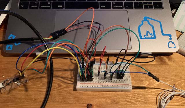
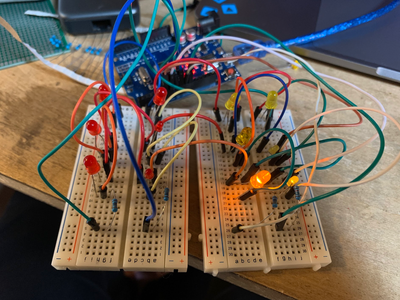
I wired everything onto breadboard to prototype.
I firstly refered to the code in this page, wrote this program with the rows connected to pin 5-7, columns to 8-11.
// anodes
int row[] = {5,6,7};
// cathodes
int col[] = {8,9,10,11};

void setup()
{
  for (int i=0;i<4;i++)
  {
    pinMode(row[i], OUTPUT);
    pinMode(col[i], OUTPUT);
  }
  allOff();
}


void loop()
{
  digitalWrite(row[2], HIGH);
  digitalWrite(col[2], LOW);
}

void allOff()
{
  for (int i=0;i<4;i++)
  {
    digitalWrite(row[i], LOW);
    digitalWrite(col[i], HIGH);
  }
}
And it lit up!
However, this would get very long if I want to light up more or if I want to change the lighting pattern more frequently.
So I learned a way to program when actually writing matrix.
I refered to this Japanese site to write this program.
The position with 1 in matrix is lit up.
//4*4 matrix, only the first 3 rows are used since the LED matrix is 3*4
int matrix[4][4] = {
  {0,0,0,0},
  {0,0,0,0},
  {0,0,0,0},
  {0,0,1,0}
};
void setup(){
  // set pin 5-11 as output
  for(int i=5;i<=11;i++){
    pinMode(i,OUTPUT);
    digitalWrite(i,HIGH);
  }
}

void loop(){
  // pin 5-7 for row
  for( int i = 5 ; i <= 7 ; i++ ){

    // set row all to LOW
    digitalWrite( i , LOW );

    // pin 8-11
    for( int j = 8 ; j <= 11 ; j++ ){
      digitalWrite( j , ledmatrix[ i - 2 ][ j - 10 ] );
      delay(100);
      digitalWrite( j , LOW );
    }
    // set row all to high, turn off all
    digitalWrite( i , HIGH );
  }
}
If I add matrix[2][0] =1; at the beginning of loop, this sets row 3, column 1 in the matrix to 1, thus lights up that LED.
Wiring
Each pin of ATMega328 is able to provide 40mA. Experimenting with high brightness LED, I figured that even with 1KOhm resistor connected to each LED, 40mA was still enough to light up 4 LEDs connected in a parallel manner.
It seems that if the current is not enough, transistor could be used to amplify the current.
So I used 1KOhm for each LED without a transistor.
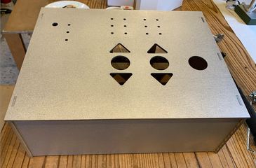
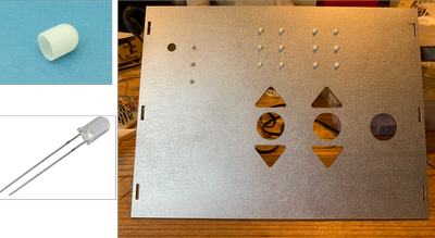
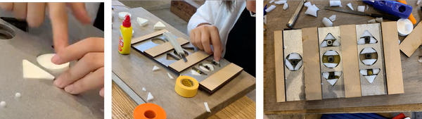
After putting cap onto the LED, I used glue gun to stick the LED onto the control panel.
On the back, I cut the legs of LEDs shorter while making sure that the length of cathode is different from that of anode. This creates a 3D structure to prevent shorting.
Then I soldered nichrome wire to each legs.
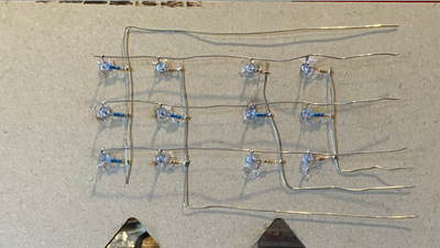
The nichrome wire was later soldered onto jumper wire to go into MCU.
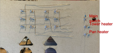
The other 3 LEDs are indicators whether the main switch, heater for the condense tower, heater for the pan are on.
They were individually connected to power supply, SSR for either heaters.
Tactile switches on the control panel
Prototype
I am using 7 tactile switches. Similar to LEDs, there are only 6 analog pins, so I applied a method to connect multiple tactile switches onto 1 pin.
I refered to this Japanese page and this page.
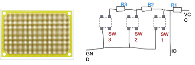
3 tact switches are connected in this way. I used 10K Ohm resistors.
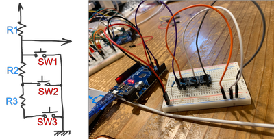
And I ran this program:
const int PIN_ANALOG_INPUT = 5;

void setup() {
  Serial.begin( 9600 );
}

void loop() {
  int i = analogRead( PIN_ANALOG_INPUT );
  float f = i * 5.0 / 1023.0;
  Serial.println( f );
  delay( 1000 );
}
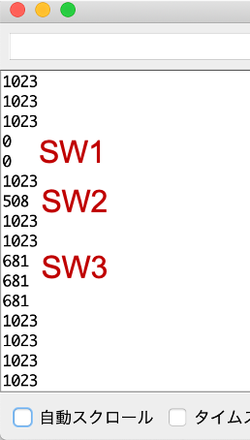
When no switch is pressed, IO pin is connnected to 5V, thus 1023 in serial monitor’s analog read.
When SW1 is pressed, IO pin is in between R1 and GND, thus 0V and 0 in serial analog read.
When SW2 is pressed, IO pin is in between R1 and R2, thus half of the voltage -> 2.5V and somewhat between 500 and 550 in analog read. (The accurate number would be 512 but there can be a bit of error.)
When SW3 is pressed, IO pin is between R1 and R2 + R3, thus 2/3 of the voltage -> 10/3 V and somewhere between 650 and 700.
Wiring & assembly
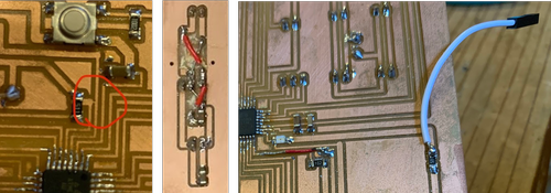
I used universal board to connect tact switches and resistors to the I/O pins.
I inserted the tact switches from the back of the board so I can solder the legs onto the board.
Then I soldered everything with nichrome wire in this manner.
For the assembly, I cut out a piece of MDF that has same slots for buttons as the top of control panel.
Universal boards were screwed onto it, and some slits of MDF are attached to it with double side tape.
The slits go onto the top of the control panel. At first I used double sided tape, but it wasn’t stable, so I ended up screwing it on control panel.
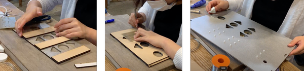
When putting the tact switch caps on, they seem to be a bit unbalanced. So I cut some sponge and glued them onto the universal boards around the tactile switches under the cap.
And then it worked well!
DC motor & Solenoid valve control
To drive DC motor and solenoid volve, I used NchFET(N channel MOSFET) 2SK4017 (datasheet in Japanese) as motor driver.
I connected it like this.
According to the data sheet, the 3 legs of 2SK4017 1, 2, 3 each goes to gate (G), drain (D), and source (S).
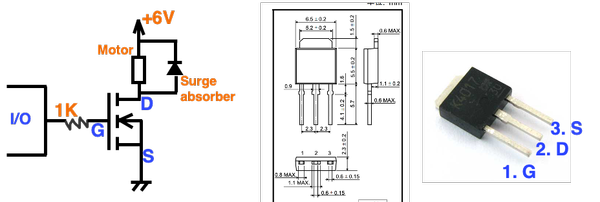
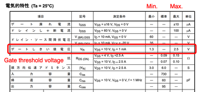
It enables circuit flow once the gate voltage supply reaches gate shreshold value.
This applies the same to solenoid valve with 12V supply.
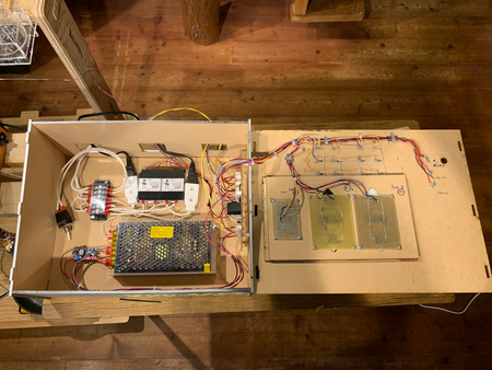
Power supply
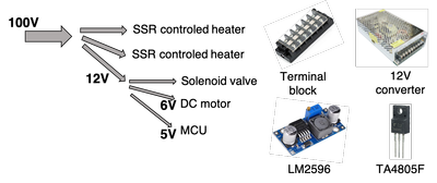
Theses are the power supply I need for this project.
-
100V for 2 SSR controled heater
-
12V for solenoid valve
-
6V for DC motor
-
5V for MCU using ATmega328
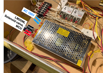
100V is taken directly from a plug, connected through terminal block (端子台).
For 12V, 6V, 5V, I converted 100V to 12V using a AC-DC converter, and converted 12V to 6V using LM2596, to 5V using TA4805F.
100V terminal block
I used a terminal block so the whole system’s electricity can be provided with 1 plug into 100V.
To make cables to connect to terminal block, I stripped around 7mm of a cable, twisted the wire inside, put the head on, and used caulking machine to fix the head onto the wire.
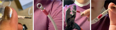
It ended up like this.
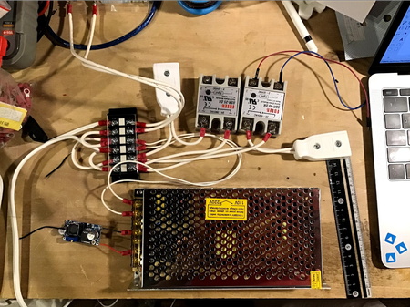
12V converter
100V AC goes into the converter, VCC & GND of LM2956, Solenoid valve, MCU (TA4850F embedded) go from the converter to obtain 12V DC.
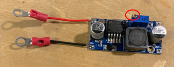
LM2596
LM2596 is a step down voltage regulator. Here is the datasheet
I followed this tutorial video, connected IN- & IN+ to 12V output, and connected OUT- & OUT+ to MCU.
After connecting, I used a driver to loosen and tighten the screw to adjust the output voltage to 6V.
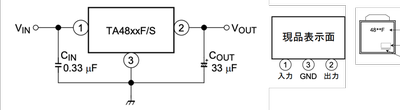
TA4805F
TA4805F is also a stepdown voltage regulator.
The datasheet of TA4805F is here.
The connection is like this.
I used both 10µF capacitors for Cin and Cout.
When the face with lot numbers etc. is facing up, the legs are lined up as 1. in, 3. GND, 2. out.
MCU
I used ATmega 328 for my MCU, and I remade Satshakit.
These are the input & output devices:
| PIN NUMBER | INPUT DEVICE | WHAT DOES IT DO |
|---|---|---|
| A0 | 3 tact switches for the Tower Heating Temperature set up | Change the setting of heating temperature of heater. Start heater. |
| A1 | 3 tact switches for the Outlet Timespan set up | Change the setting of span of solenoid valve’s open time. Start peristaltic pump and solenoid valve. |
| A2 | 1 tact switch for Salt production | Turn the heater for condensed ocean water on and off. |
| A3 | Thermistor | Monitor the temperature of condense tower for the hysterisis control of heating. |
| PIN NUMBER | OUTPUT DEVICE | WHAT DOES IT DO |
|---|---|---|
| D2,D3 | SSR1, SSR2 | Control the on/off of heaters |
| D5, D6, D7 | Row of LED matrix | Send out high/low signal to control the LED matrix |
| D8, D9, D10, D11 | Column of LED matrix | Send out high/low signal to control the LED matrix |
| D12 | DC motor | Control the on/off of peristaltic pump |
| D13 | Solenoid valve | Control the on/off of solenoid valve |
Pin layout:
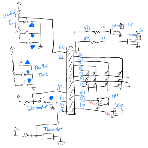
A0 - 3 tact switches for the Tower Heating Temperature set up
A1 - 3 tact switches for the Outlet Timespan set up
A2 - 1 tact switch for Salt production
A3 - thermistor
A4, A5 - vacant
D0, D1 - reserved for Tx Rx
D2, D3 - SSR1, SSR2
D4 - vacant
D5, D6, D7 - Row of LED matrix
D8, D9, D10, D11 - Column of LED matrix
D12 - DC motor
D13 - solenoid valve
Since I will put my MCU in the control panel which is fairly big, I decided to make a larger MCU.
The XH connectors going into different devices were put on the back of MCU.
I also drilled several holes that serve as jumper for VCC and GND on the board.
EAGLE
I opened “satshakit cnc schematic” file on EAGLE. To keep the pretty layout of satshakit, I edited one pin in Schematic, laid out the parts in Board, and then proceeded to the next pin in Schematic.
At the beginning, I edited everything in Schematic, then tried to lay out parts in Board. The previous pretty layout was already a mess at that time.
This is the Schematic of the MCU.
Left half:
I added the parts to retain 5V from 12V onto the MCU.
I added holes as jumper for VCC and GND so that it’s easier to lay out parts.
There were many pairs of VCC and GND to supply power for LED, SSR, etc.
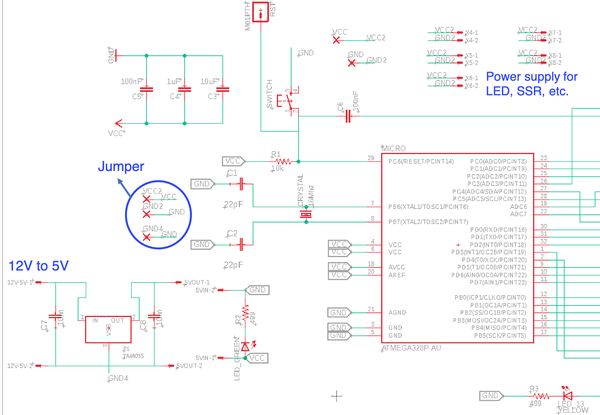
Right half:
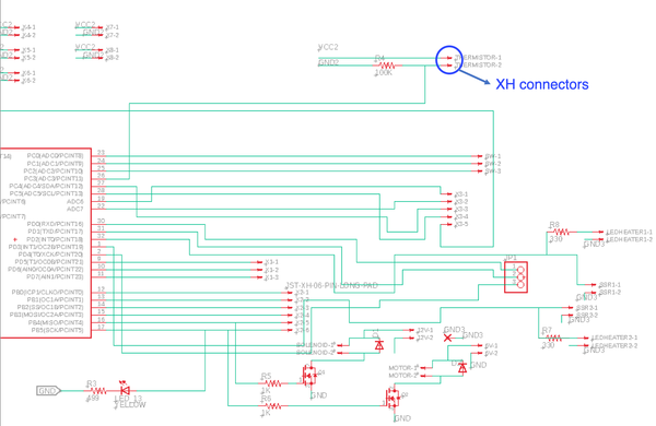
This is board of the MCU.
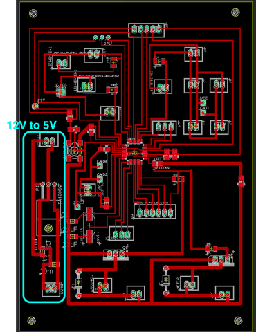
The 4 holes on the edges are to fix the MCU onto the control panel with screws. So the diameters are 3.2mm.
To prevent short-circuit caused by the screws, I made sure that no pattern is within the circle with a diameter of 7mm from the screws.
Production
Milling PCB
Besides the traces and outline data, this time I also made data for drilling holes.
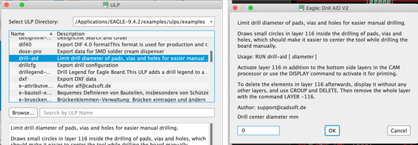
I refered to this page about how to drill holes in Eagle.
In File > Run ULP, I opened “drill-aid”.
I changed drill center diamter mm to 0 (0.3 as default) and clicked OK.
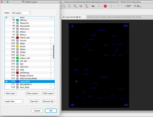
In View > Layer settings…, I set to show only Layer 116 centerDrill. And I exported the data as monochrome with 800dpi as other layers.
In MODS, I inverted the image, and generated toolpath with 1/32 inch mill.
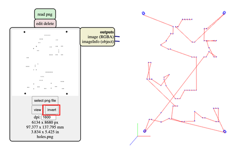
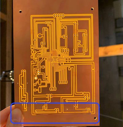
I ended up using the entire copper laminated boards so I milled the traces with 1/64 inch mill, the holes with 1/32 inch mill, and didn’t cut the outlines.
There are some places that are not milled properly, I used sonic cutter to create the traces.
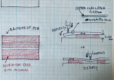
To mill larger boards, it is important to tape the copper laminated board entirely onto the sacrifice board.
Jun-san drew this very nice illustration to explain why.
With Rico’s word, any area of the board’s back side that does not have tape may deflect or distort under the downward force of the endmill. And this would cause milling problems.
Soldering
Here are the components I used.
| Component | Specification | Number | Name |
|---|---|---|---|
| micro controller | ATMega328 | 1 | |
| switch | tact | 1 | |
| capacitor | 22pF | 2 | C1, C2 |
| capacitor | 10uF | 4 | C3, C7, C8 |
| capacitor | 1uF | 1 | C4 |
| capacitor | 100nF | 2 | C5, C6 |
| resistor | 10KΩ | 1 | R1 |
| resistor | 499Ω | 2 | R2, R3 |
| resistor | 100KΩ | 1 | R4 |
| resistor | 1KΩ | 2 | R5, R6 |
| led | yellow | 2 | |
| crystal | 16MHz | 1 | |
| header | 1*3 | 1 | |
| header | 1*1 | 1 | |
| XH connector | 1*2 | 15 |
I soldered all the parts onto the board. XH connectors go to the back of the board. And I used jumper wires to connect jumper holes I made for VCC and GND.
I screwed heatsink fins onto TA4805F to dissipate heat generated by the voltage step down process.
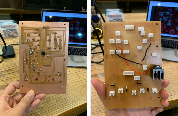
Debugging
The board in the picture was the one I used in the end. However, before that, there was a previous version where many mistakes were made, and many “surgeries” were conducted to the board.
In the previous board,
-
there were 2 paths that were not supposed to be connected, accidently connected. This was able to be detected by eyes.
-
I mistook the legs for TA4805F so the connection was reversed. I used sonic cutter to cut the paths off and used jumper wire to connect the paths that are supposed to be connected.
-
I didn’t realize that SCK, MISO, etc, are necessary for writing programs, and I didn’t make pins for that. So I soldered jumper wire with a connector at the end onto the paths coming out from those pins.
However, the deadliest mistake I made is that, I soldered ATMega48 instead of ATMega328… I tried to desolder it but it didn’t work at all.
So I updated my EAGLE file by correcting the mistakes I found, and milled PCB again,
Burn bootloader
I used an Arduino UNO to burn bootloader.
I firstly wrote the program of Arduino as ISP onto Arduino UNO, and connected VCC, GND, SCK, MISO, MOSI, RST of Arduino UNO and MCU.
And then I selected Arduino UNO as the board, Arduino as ISP, and burned bootloader.
wiring
I had to make 15 XH connector heads. Since the XH connectors are on the back of the board, I had to be really careful about the position of cables.
I taped the head of each cable indicating which is which so I won’t get lost after.
To make the wires look more neat, I twisted the wires that go into the same XH connector. And then I used cable ties to tie up wires that go into the same area (e.g. the wires that all go into the LEDs and switchs on the surface of control panel.)
According to Rico, regarding wire twisting, it is more than just making things neat. “By default, the flow of current generates an electromagnetic field of interference around the wire that creates noise the can impact signals being transmitted through surrounding wire and cable. In order to help eliminate this electromagnetic interference, the wire is twisted together to create a canceling effect.”
Bonus - Salinity test
It was unfinished and triaged, but I tried to make salinity sensor to demonstrate the change in salinity before and after the distillation.
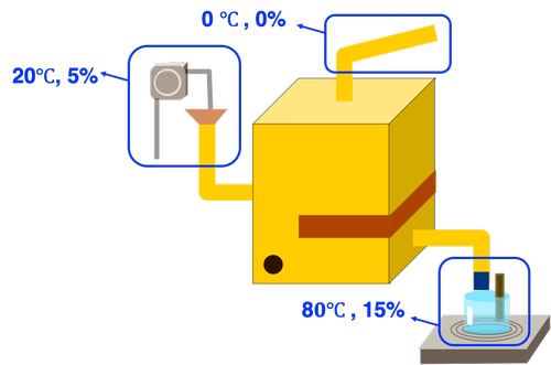
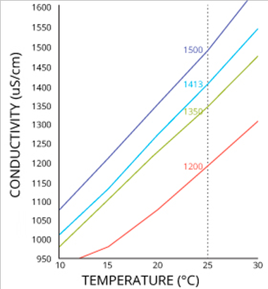
Conductivity changes based on the salinity and temperature according to this site.
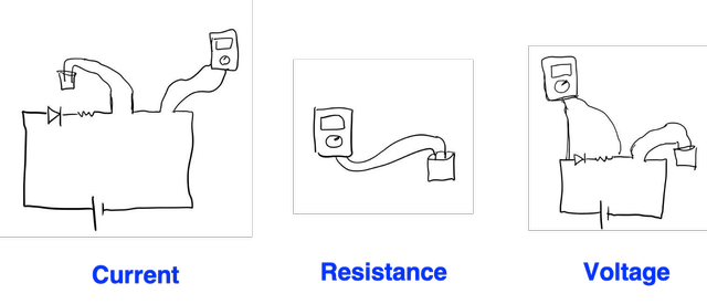
Any of these means to measure current, resistance, voltage should show difference among different salinity.
I made dissolvant of salt water, 0%, 5% (5g salt + 95ml water), 15% (15g salt, 85ml water), and used jumper wire as the electrodes to test the current.
You can see the difference in current among the different dissolvants.
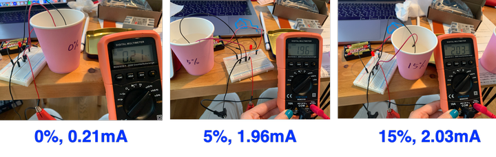
However, the current is not very stable, it fluctuates a lot. And I can see the jumper wire dissolving in the salt water with bubble generated, and the dissolvant became yellow after a while.
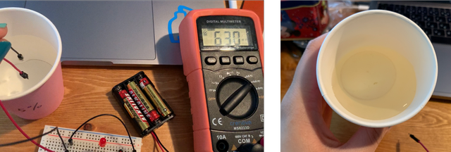
Jumper wire’s head is made of tin plated iron, so no doubt it is dissolving…
I then refered to this page, stripped the coat of the wire, and connected it with nichrome wire.
And I taped the nichrome wire onto a pen with vinyl tape, leaving a bit sticking out.
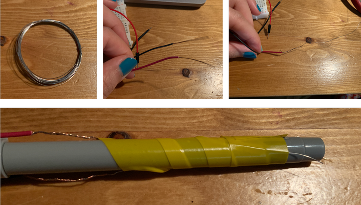
And I used USB instead of batteries (since the voltage could drop after they are consumed) to provide power.
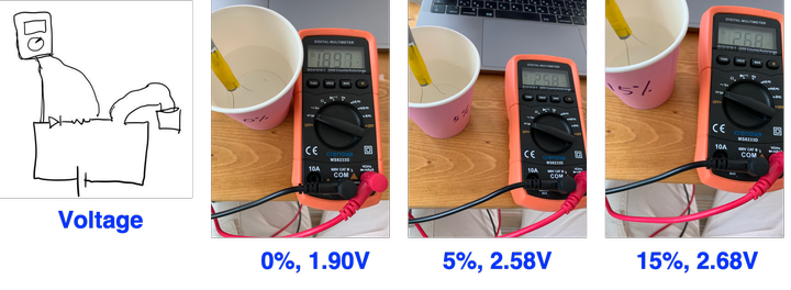
This is the reads for voltage:
This is the reads for resistance:
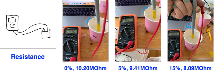
You can see the difference among different dissolvants.
However, the read still changes (not as drastically but still), so I should decide on a specific timing for reading (e.g. 5 seconds after I put it into the dissolvant).