11. Output devices
Assignment
- Individual assignment:
- Add an output device to a microcontroller board you’ve designed,
- and program it to do something
- Group assignment:
- Measure the power consumption of an output device
Group assignment
The group page is here.
Make a servo motor move
This week I worked on servo motor SG90 (datasheet) by Tower Pro Pte Ltd as an output device.
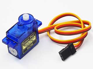
According to this page,
The servo motor is most commonly used for high technology devices in the industrial applications like automation technology. It is a self contained electrical device, that rotates parts of machine with high efficiency and great precision. Moreover the output shaft of this motor can be moved to a particular angle. Servo motors are mainly used in home electronics, toys, cars, airplanes and many more devices.
Unlike DC motor, you can assign it to move to certain degree. However, it only moves from 0-360 degress, so it doesn’t rotate beyond that.
And you don’t need a motor driver to drive it unlike DC motor and stepper motor.
Prototype on a breadboard
I refered to this board to connect these components on a breadboard:
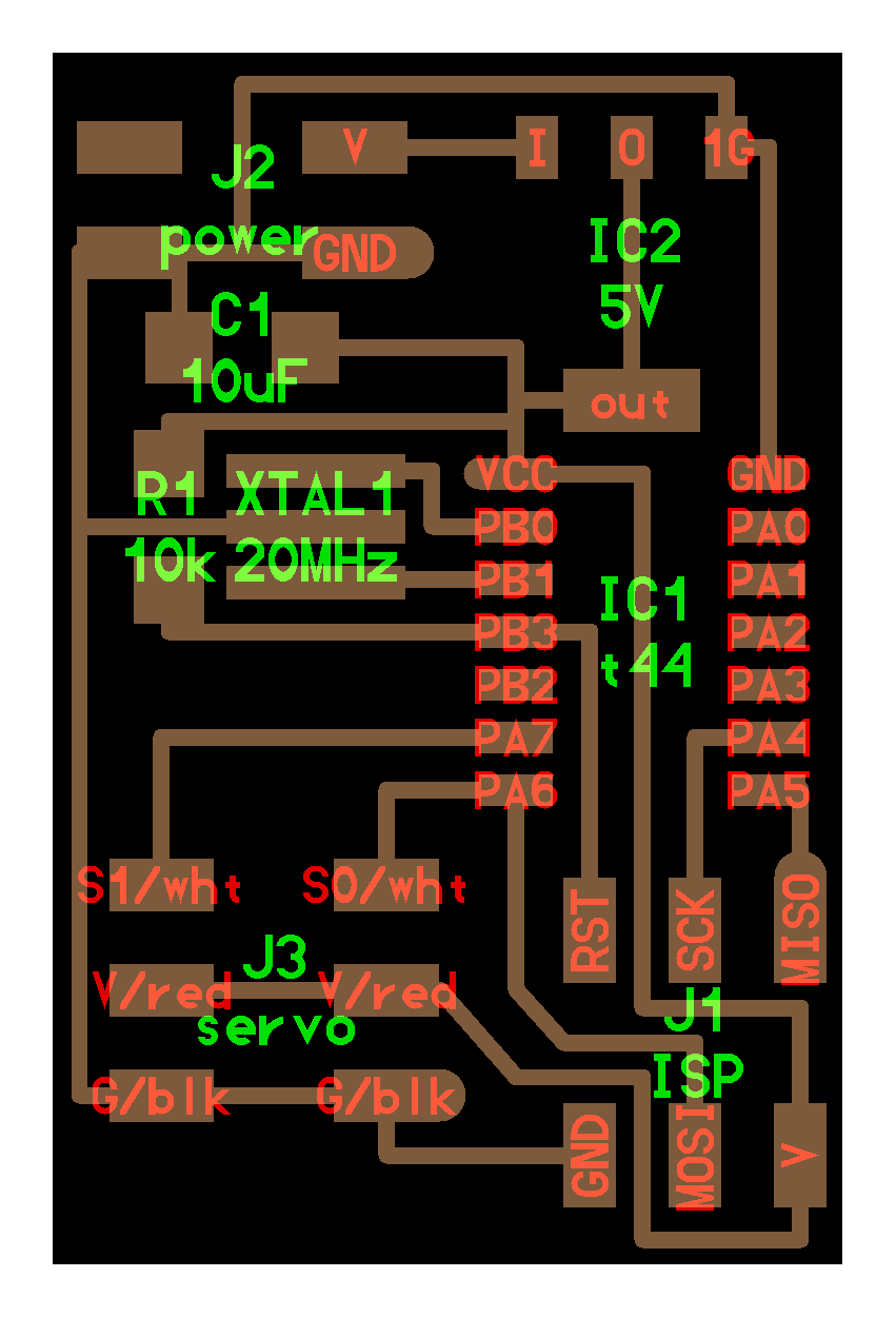
- ATTiny44 * 1
- 20MHz resonator * 1
- 10mF capacitor * 1
- 10kOhm resistor * 1
- SG90 servo motor * 1
- FabTinyISP * 1
- FTDI cable * 1 (for power supply)
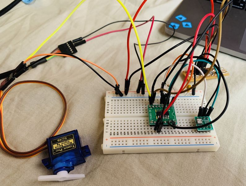
Instead of using 9V battery and a regulator, I used FTDI cable to obtain electricity.
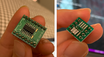
At first, I soldered ATTiny 44 and resonator onto PCB boards so they fit onto the breadboard.
For the resonator, I used number 1-3 pads on the board. The soldering process was very challenging…
Then I connected all the parts.
I used PA6 to connect to the PWM pin of 1 motor.
Run the sample code
Servo motor is controlled under PWM.
According to this page,
PWM is a way to control analog devices with a digital output. Another way to put it is that you can output a modulating signal from a digital device such as an MCU to drive an analog device. It’s one of the primary means by which MCUs drive analog devices like variable-speed motors, dimmable lights, actuators, and speakers. PWM is not true analog output, however. PWM “fakes” an analog-like result by applying power in pulses, or short bursts of regulated voltage.
In reality, the voltage is being applied and then removed many times in an interval, but what you experience is an analog-like response.
In this way, you do not experience an abrupt stop in power if a motor is driven by PWM.

So after connecting, I plugged FabTinyISP into my computer, and tried to run the sample .c file and .c.make file of hardward PWM.
When I ran $ make -f hello.servo.44.c.make in terminal, I got an error message:
make: hello.servo.44.c.make: No such file or directory
make: *** No rule to make target `hello.servo.44.c.make'.  Stop.
Then I discovered that the .c.make file I downloaded was named hello.servo.44.make. So I changed the name into hello.servo.44.c.make and it worked.
Then I ran
$  sudo make -f hello.servo.44.c.make program-usbtiny-fuses
$  sudo make -f hello.servo.44.c.make program-usbtiny
and the motor moved.
Test the current and voltage in the circuit
To see how much electricity is consumed when the motor is moving, I used a multimeter to test the current and voltage going through the circuit.
The multimeter is connected in between the power supply, and the wires going in to VCC and GND of the breadboard.
Current
Firstly I tested the current.
When there is no motor connected, the current reads 0.013A.
When there is motor connected, the current fluctuate according to the movement of the motor.
The current should be the same when the motor is moving. However, since the timing of measurement is not perfectly tuned to the movement of the motor, the number fluctuate.
The current goes up to 0.279A in the video, and that represents the current consumed in the whole circuit when the motor is moving.
Therefore, the current the motor consumed when moving is
0.279 - 0.013 = 0.266 A
Voltage
Then I tested the voltage.
When there is no motor connected, the voltage reads 5.12V.
When there is motor connected, the voltage fluctuate according to the movement of the motor.
The voltage goes down to 4.86V so I assume it is the voltage level when the motor is moving.
There for, the voltage cosumed by the motor when moving is
5.12 - 4.86 = 0.26 V
Program to change the motor’s movement
I tried to customize the .c code to change the movement of the motor.
I figured that the main loop part in the code is where I should edit to change the angle of the movement.
// main loop
   //
   while (1) {
      //
      // 1 ms PWM on time
      //
      OCR1A = 1250;
      position_delay();
      //
      // 1.5 ms PWM on time
      //
      OCR1A = 1875;
      position_delay();
      //
      // 2 ms PWM on time
      //
      OCR1A = 2500;
      position_delay();
      }
   }
According to the datasheet, position “0” (1.45 ms pulse) is middle, “90” (~2.4 ms pulse) is all the way to the right, “-90” (~ 0.5 ms pulse) is all the way left.
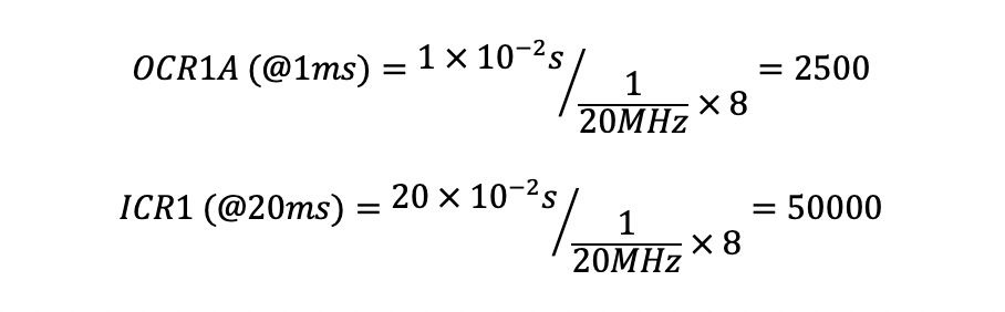
I tried to do some calculation but it didn’t match with the sample code.
According to my calculation, the OCR1A at 1ms should be 2500.
And if the frequency is set to 20ms, then ICR1 should be 50000 not 25000 in this line in the code ICR1 = 25000; // 20 ms frequency…
To ensure that everything is set correctly, I re-read the .c and .c.make file, and compared it with the ATTiny44 datasheet.
- Clock set to 20MHz in .c.make file:
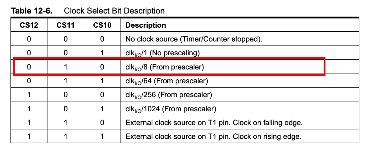
F_CPU = 20000000 - Prescaler set to 8 in .c file:
(0 << CS12) | (1 << CS11) | (0 << CS10)
And then I realized that it is written (1 << WGM13), which means the PWM is set to phase and frequency correct mode!!
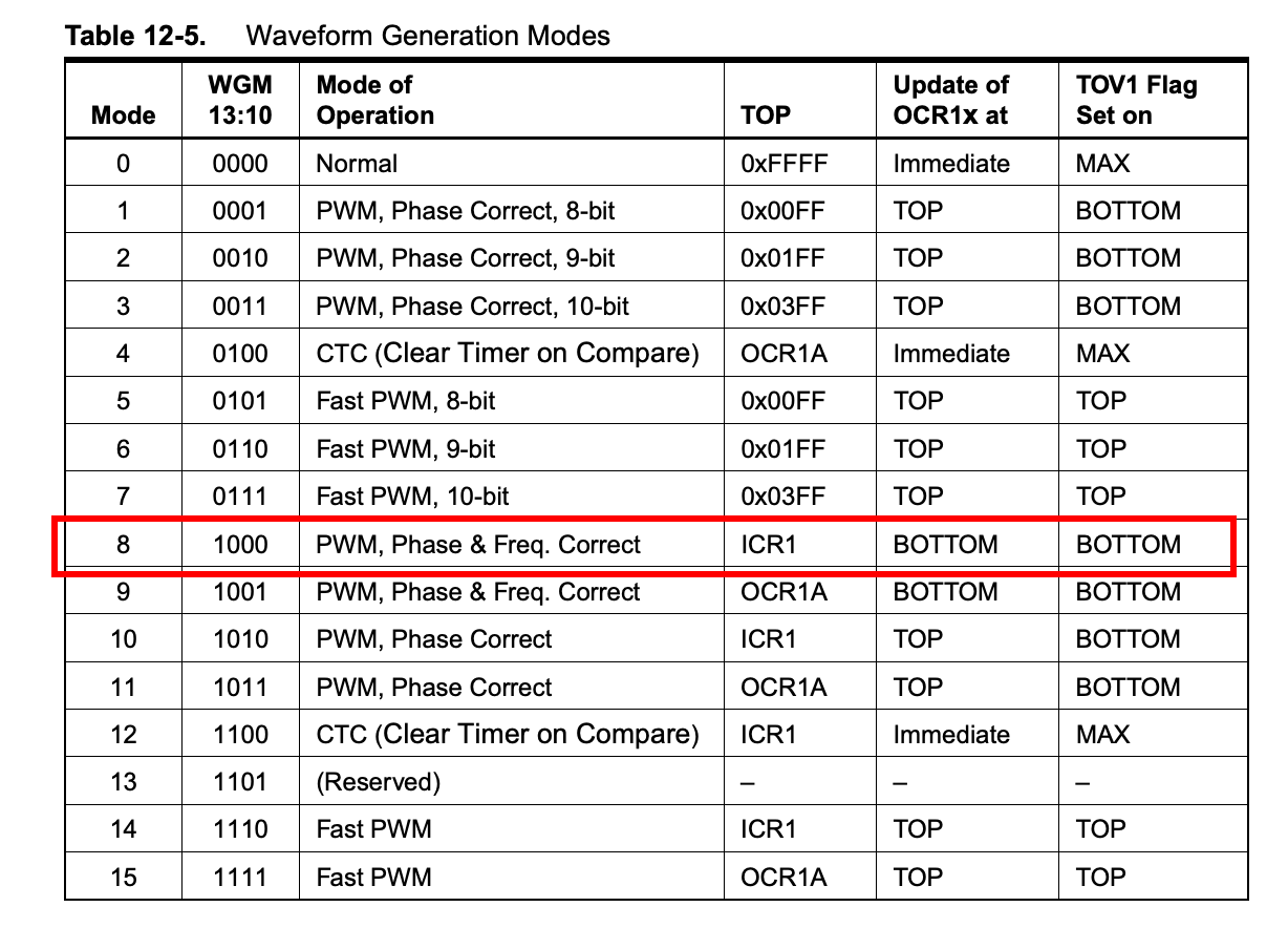
I did some research on phase and frequency correct mode. Don’t think I understood it fully, but according to this page, I understood that the output frequency will be approximately half of the value for fast PWM mode.
So this explains why the number is half of what I calculated!
To have the motor moving from one end to the other end, I changed the main loop of the code into:
// main loop
   //
   while (1) {
      //
      // 0.5 ms PWM on time
      //
      OCR1A = 625;
      position_delay();
      //
      // 1.5 ms PWM on time
      //
      OCR1A = 1875;
      position_delay();
      //
      // 2.4 ms PWM on time
      //
      OCR1A = 3000;
      position_delay();
      }
   }
And it worked!
Change to other PWM modes
I tried to set the PWM into other mode.
I wanted to keep the top to ICR1, so I chose CTC (number 12) in this chart.
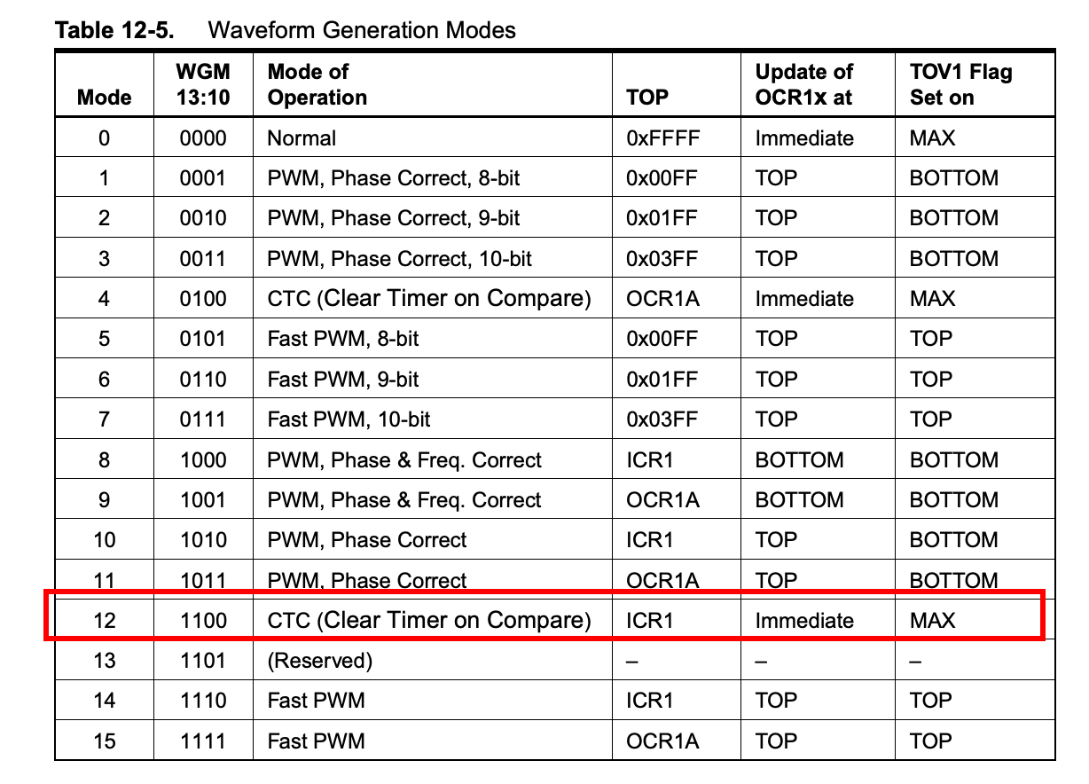
It indicates that WGM13 and WGM12 should be 1, so I changed the code into
TCCR1B = (0 << CS12) | (1 << CS11) | (0 << CS10) | (1 << WGM13)| (1 << WGM12);
However, the motor didn’t move at all…
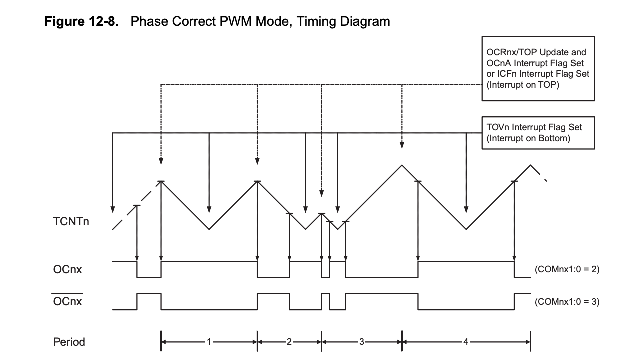
My understanding is that the phase correct output has the output pulses centered in the cycle instead of rising at the start of the cycle, and the phase correct modes gives you half frequency compared to fast PWM.
I asked Neil why was phase corrected PWM used instead of fast PWM, and he said that for motors it doesnt matter much, but for applications that are more sensitive like sound, it does matter.
Control a servo motor with the input from a thermistor
Program
I connected the servo motor to a thermistor as heat sensor.
The idea is to have the motor moves when the read of the thermistor exceeds a certain number.
I connected the thermistor as what I did in week 9 (link) to the existing circuit. The digital signal goes to pin2.
I firstly tried to run this code:
#include <Servo.h>
#define THERMISTORPIN 2
Servo myservo;
void setup(void) {
  myservo.attach(6);
  Serial.begin(9600);
}
void loop(void) {
  float reading;
  reading = analogRead(THERMISTORPIN);
  Serial.println(reading);
    if(reading >780){
      myservo.write(0);
  }
  else{myservo.write(100);
  }
  delay(2000);
}
However, I got an error message. Apparently the size of the code exceeds the memory size…
Multiple libraries were found for "Servo.h"
 Used: /Users/yumexu/Library/Arduino15/packages/ATTinyCore/hardware/avr/1.2.4/libraries/Servo
 Not used: /Applications/Arduino.app/Contents/Java/libraries/Servo
Using library Servo at version 1.1.2 in folder: /Users/yumexu/Library/Arduino15/packages/ATTinyCore/hardware/avr/1.2.4/libraries/Servo
/Applications/Arduino.app/Contents/Java/hardware/tools/avr/bin/avr-size -A /var/folders/3t/5p_rd_h14n1fhfr9167p_0740000gn/T/arduino_build_342600/ther.moter.ino.elf
Sketch uses 4902 bytes (119%) of program storage space. Maximum is 4096 bytes.
text section exceeds available space in board
Global variables use 107 bytes (41%) of dynamic memory, leaving 149 bytes for local variables. Maximum is 256 bytes.
Sketch too big; see http://www.arduino.cc/en/Guide/Troubleshooting#size for tips on reducing it.
Error compiling for board ATtiny24/44/84.
I deleted delay(2000); and it went through.
#include <Servo.h>

#define THERMISTORPIN 2


Servo myservo;

void setup(void) {
  myservo.attach(6);
  Serial.begin(9600);
}

void loop(void) {
  float reading;

  reading = analogRead(THERMISTORPIN);
  if(reading>780){
      myservo.write(0);
  }
  else{myservo.write(100);
  }
}
It worked, but I want to get rid of the gitter…
Maybe if I added the delay line, it would gitter less?
Anyways, I want to program it so a library is not needed. Maybe using software PWM, or code with C language based on the hello.servo.c code.
Board production
For my final project, I designed, produced, and programmed a board with multiple output functions. The devices include SSR control, DC motor, LED matrix, and solenoid valve.
For further detail, please refer to my final project - electronics page and final project - programming page.