3. Computer controlled cutting
Assignment
- Group assignment
Characterize your lasercutter’s focus, power, speed, rate, kerf, and joint clearance document your work (individually or in group) - Individual assignments
Design, lasercut, and document a parametric press-fit construction kit, which can be assembled in multiple ways. Account for the lasercutter kerf. Cut something on the vinylcutter.
Group assignment
Check out the Kamakura site page here
Parametric press-fit construction kit
I found this idea on Instructables and decided to model it with parametric design.
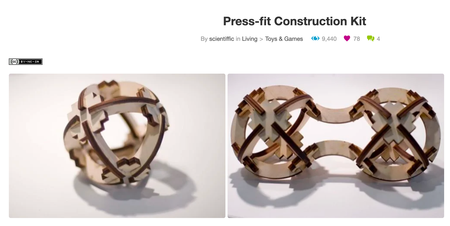
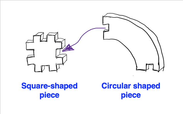
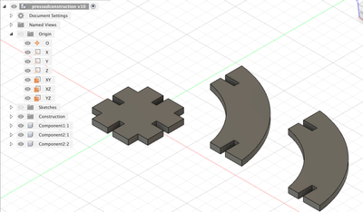
It consists of 2 parts, the square-shaped piece, and the circular shaped piece.
The gap between the teeth of both pieces fits into each other vertically.
Sketch
I used Fusion360 to create the sketch.
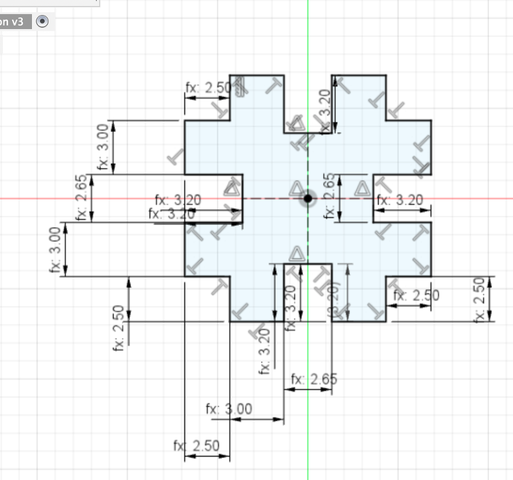
I started with the square-shaped piece.
To sketch the shape, I firstly tried to make the square outside, and drew 1 small rectangle on the 1 corner and mirrored it to 4 corners.
However, when I tried to trim the unnecessary parts, the constraints disappeared. It seems like this doesn’t work (especially mirroring does not include the constraints).
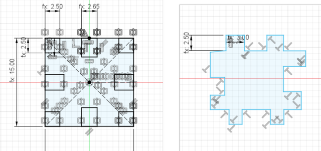
So I drew each sides one by one, set constraints so all angles are 90 degress.
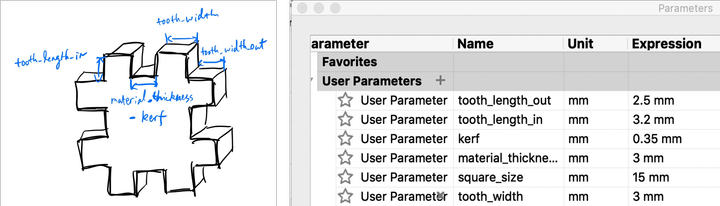
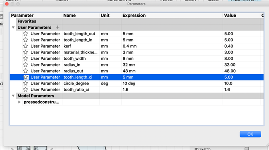
5 parameters are used in this shape.
“tooth_length_in”, “tooth_width_out”, “tooth_width” are used for the dimensions of the teeth.
The dimension in between 2 teeth is defined as “material_thickness - kerf” since the circular shaped piece will fit in here vertically.
Modify > Change Parameters was opened to set the parameters. (square_size wasn’t used.)
It looked like this when finished.
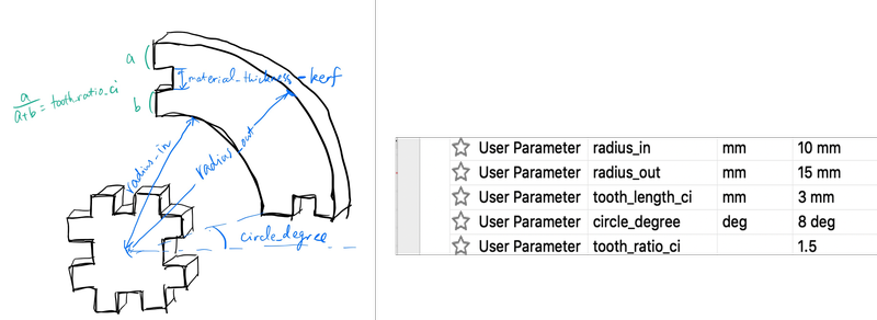
And I drew the circular shaped piece. The dimensions are defined based on that of the square-shaped piece.
“radius_out” and “radius_in” are the radius of the inner and out circle with the center of the square-shaped as the center.
The distance between 2 teeth is also defined as “material_thickness - kerf” since the square-shaped piece will fit in here vertically.
The size of upper tooth and the size of lower tooth follow a ratio.
The edge of the circular shaped piece and the center line of the square-shaped piece forms a degree of “circle_degree”.
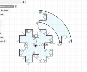
It looked like this when finished.
Generate vector data
Vector data is used for laser cutter.
To export vector file from Fusion 360’s sketch, set an offset plane above the extruded sketch and projected the sketch onto there, and export the projected sketch as .dxf file (File > Export).
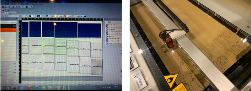
Create cut data
I used TROTEC Speedy 100 to cut the cardboard.
After exporting the vector data into .dxf file, I opened it with Inkscape to edited the sketch so
-
the lines are colored red
-
the line width is set to 0.010mm
In the software used for Trotec, you can set cut parameters for a specific color. Usually red lines are set as cut and black for engraving.
And you need to set the lines as thin as 0.010mm to have the machine cutting.
After saving the file, I used an USB to transport it to the laptop connected to the laser cutter.
I opened the same file with Inkscape, pressed “Print”, chose Trotec engraver, and made sure that “Advanced geometry” and “Starting from Internal geometry” is checked in the setting.
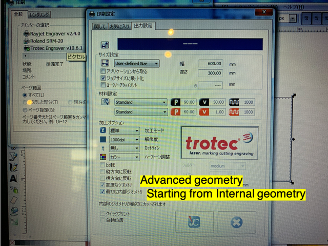
It opens JobControl Vision - a control software of Trotec laser cutters.
In Print > Advanced settings, I set the cut parameters.
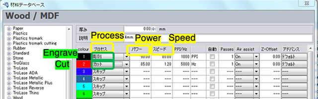
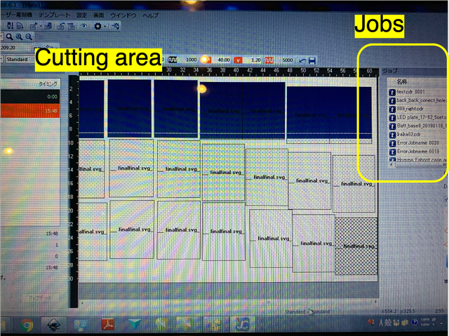
The file would show up on the right as one of the jobs.
To execute it, drag the job to the cut area. Copy & paste was used to generate more of it.
Setup laser cutter
Hideo Oguri described the setup to the laser cutter very well in the group assignment.
The following steps explained are all from there.
-
LASER CUTTER BOOT UP ( TROTEC SPEEDY100 )
-
turn on the Laser Cutter (during the starting procedure, the cover of the Laser Cutter should be closed. )
-
After the green-light ( on the operation panel ) turns on, open the cover, then place the material on the grid.
-
move the laser head to the material, then set the focusing gauge on the laser head.
-
adjust the focus by moving up the grid ( push the arrow buttons on the operation panel )
-
move the laser head to the place to be cut/carved.
-
close the cover.
-
-
CUTTING/CARVING ( TROTEC SPEEDY100 + JOB CONTROL )
-
connect the PC ( Job Control ) with Laser Cutter, by clicking the “connect ” button ( just like USB connector ) in Job Control ( then, plus “+” mark appears in the plate ( left white area ). this shows the position of the laser head.
-
drag the “job” on the plate to the appropriate position. ( this will be snapped to the plus “+” mark )
-
Then, click the start button in Job Control. ( -> Cutting/Carving starts. )
-
after the process completes, move the laser head, then pick up the material.
-
to cut/carve again with the same job file, click the right button on the mouse, then “restart the job”.
-
Cut
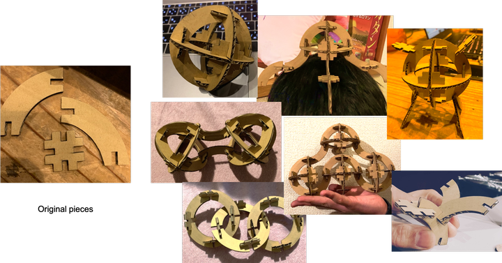
When cutting the pieces, I had some fitting issues first. So I changed the design parameters, cut, changed the parameters again, … to find the perfect fit.
These are the first 3 generations before the perfect one was cut.
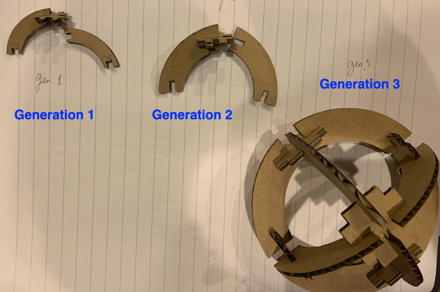
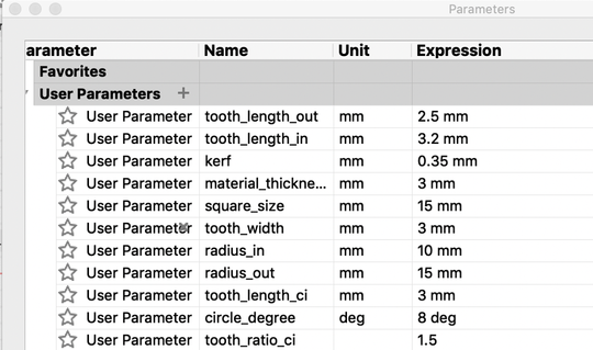
Here are the parameters set for the 1st generation.
The pieces were too small, the teeth are too short that the pieces don’t fit in well.
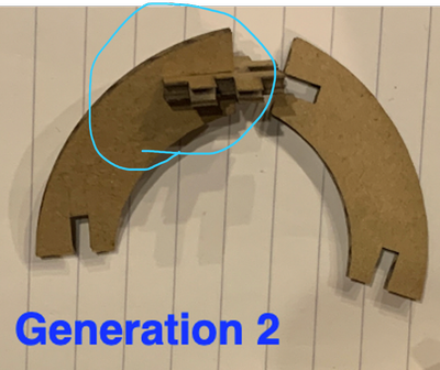
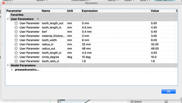
The second generation’s circular part’s teeth were too long that two pieces won’t be able to fit on the square-shaped piece together at the same time.
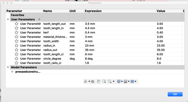
Generation 3’s slot (parameter: tooth_length_in) was too short and the slot feels a bit loose when you hold it in the air.
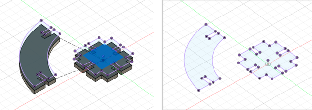
To avoid the fitting issue, I generated 3D model for these pieces by extruding the sketch and simulate the joints with joint function.
I firstly made each piece into components.
Assemble > Joint to set up for the joint. I chose the face of each piece that will be fit onto each other.
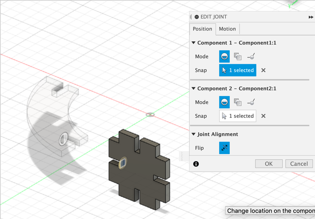
And I got the components jointed like this:
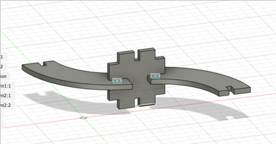
Thanks to joints, I made generation 4 with appropriate teeth length, slot width and length.
And I finally got a kit that fits perfectly with these set of dimensions.
I recognized that although when we define the kerf, 2 pieces of cardboard fit perfectly at 2.65mm, when it becomes multiple pieces that has to bear weigh, less distance - 2.45mm was actually more appropriate.
This time it fits very well!
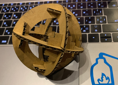
I generated a lot of them to try out different ways to construct.
You can connect the pieces to make a circle, multiple circles connected together, a ball, multiple balls connected together in multiple ways. You can also make some other shapes that are not necessarily round.
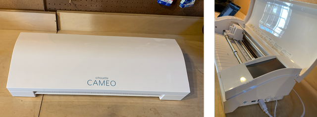
Vinyl cut sticker
I used CAMEO 4 by Silhuoette America.
Create design data
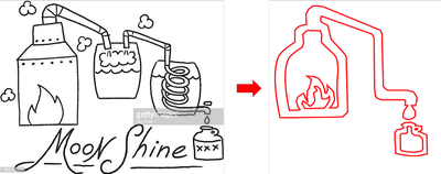
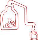
I created the data using Inkscape. I used “Draw Bezier curves and straight lines” function to draw based on an existing illustration of a distillation tower.
I noticed that if I drew exactly the same, it would only be cut as parts instead of becoming a sticker. So I created the data so it’s like the outline of the drawing.
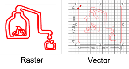
I tried to export the file as both raster (png) and vector (dxf) data.
Generate cut data
Silhouette Studio was the software used to generate cut data.
File > Import to import data. (It opens all kinds of data including svg, pdf, ai, cdr, esp, gsd, dxf, png. So both raster and vector data.
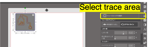
Then I opened the Trace Panel from the right, I pressed Select Trace Area, and selected the pattern I want to cut.
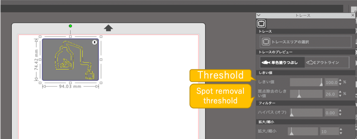
With raster (png) data, it is needed to trace the outline. I adjusted the threshold, and the spot removal threshold to find a set of shresholds where most of the line turns out to be yellow. (Yellow is the part where the machine will recognise in the data, and will cut based on that. Thus you want the trace to be cut yellow.)
Cut using vinyl cutter
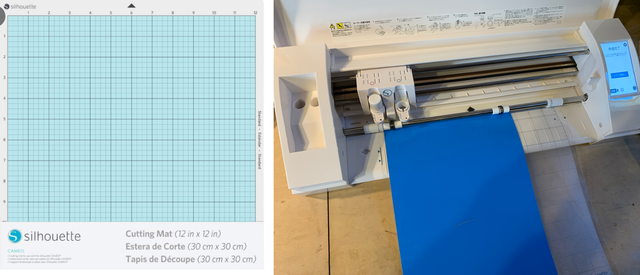
I stuck the material to be cut onto the plastic sheet that came with the machine. The left top of the material fits onto the left top of the plastic sheet’s grid.
Then I fed it into the machine.
Among the blade depth 1 to 10, I chose 3 with cut pressure 20 to cut.
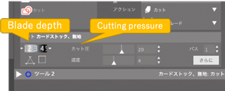
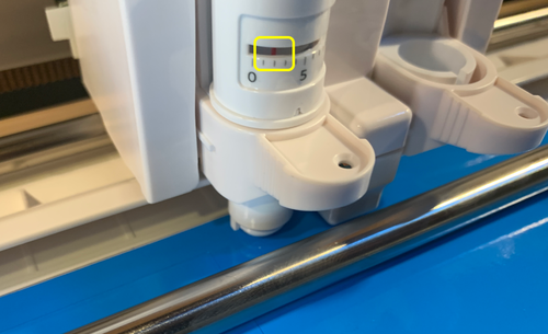
The set blade depth is also reflected on the machine.
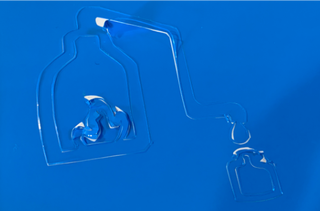
To cut, I firstly used the png file (raster data).
It turned out to be having another outline outside of the actual outline. And the cut seems to be too strong. It does not only cut through the paper behind, it also made the sticker itself seem overcut.
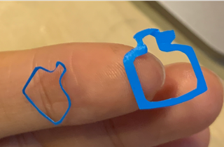
Then I used dxf file (vector data) and I did not need to trace the line. Here is the difference between how image is processed as raster data and vector data.
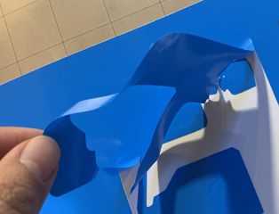
I tried blade depth 1 and 2 with cut pressure 20, but both cut through the paper underneath. I used blade depth 1 with cut pressure 15 in the end, it cut through the sticker layer without cutting through the underneath paper!
The reason we don’t want to cut through the unecessary part is for something like heat transfer sheet, you need to keep the underneath layer to use for later.
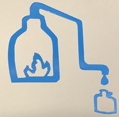
This is the sticker I made for my mini salt factory project!
Vector data only contains dots and lines, so it only contains the outline of the image. Therefore the machine cuts directly the lines.
While raster data contains the pattern as a whole, so the machine cuts the outline of the image.
After week3
- I learned about how convenient parametric design it.
- I learned that the condition might need to be stricter when you are connecting multiple things than connecting only 2 things. Since gravity is effecting more with more pieces and the slots need to be tighter.
Files
- Sketch & 3D model of the press-fit construction fit made with Fusion 360 f3d
- Vector file of the press-fit construction fit for laser cutter dxf
- Sketch of mini salt factory symbol with Inkscape svg
- Vector data of mini salt factory symbol with Inkscape dxf
- Raster data of mini salt factory symbol with Inkscape png