
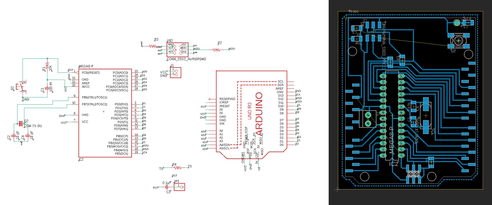
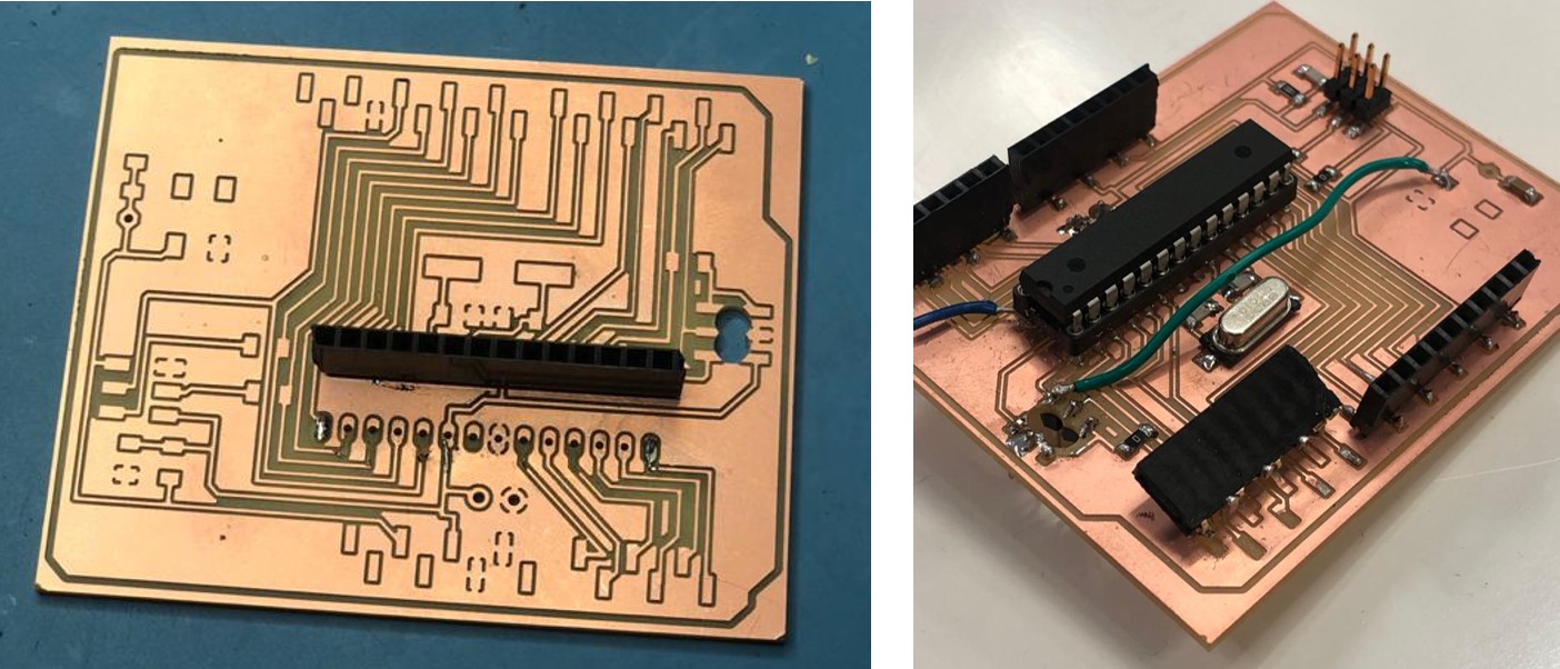
Previously in the Electronics design week, I have designed and produced an Atmega 328 board that contained 3 outputs to be used.
In this week, I am attempting to test the speaker and the screen, hence these two are critical parts of my final project.
As for the RGB LED, I have tested it with several codes and operations during the Embedded programming week.
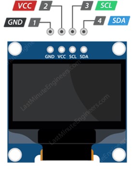
OLED or Organic Light Emitting Diodes is a flat light emitting technology, made by placing a series of organic thin films between two conductors. The organic molecules create light with the application of electricity.
OLED provide enhanced image quality, increased brightness, better contrast and reduced power consumption when compared to typical LCD or LED screens.
OLED use I2C protocol, which is a form of serial communication protocol for chip to chip communication. The protocol is a multi-master, multi-slave communication protocol which provides the means of attaching multiple chips at with the same communication bus.
To start interfacing the graphic OLED display, I went through a couple of tutorials to learn more about it operations and abilities.
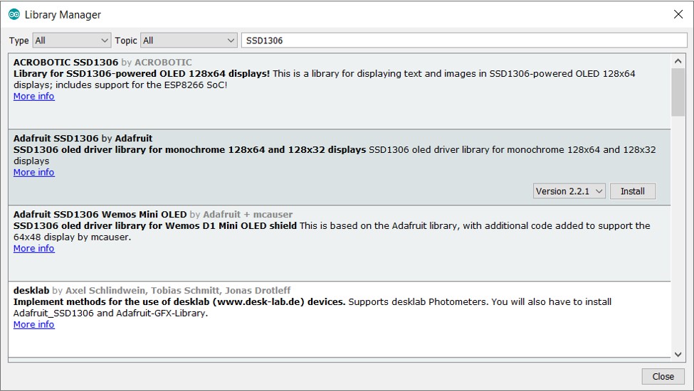
Controlling the display drivers requires installing some libraries. There are several libraries available online, but the one I saw most recommended to use is the Adafruit ssd 1306 library. To install the library I simply went to Sketch>include library>manage libraries> Type SSD 1306.
Some of the functions to handle the OLED display:
display.clearDisplay() – all pixels are off
display.drawPixel(x,y, color) – plot a pixel in the x,y coordinates
display.setTextSize(n) – set the font size, supports sizes from 1 to 8
display.setCursor(x,y) – set the coordinates to start writing text
display.print(“message”) – print the characters at location x,y
display.display() – call this method for the changes to make effect
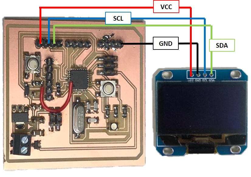
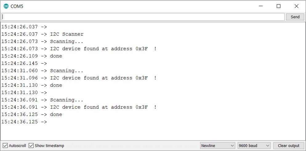
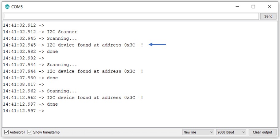
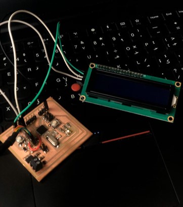
Next, I had to check the address of the I2C connection. I connected the pins on my atmega board to the display and the ran the code on Arduino IDE.
Next I tested the a basic example of the library I installed by going to file > examples > Adafruit SSD 1306 > ssd1306_128x64_i2c.
This following code uses different functions to display various shapes on the screen.
#include <SPI.h>
#include <Wire.h>
#include <Adafruit_GFX.h>
#include <Adafruit_SSD1306.h>

#define SCREEN_WIDTH 128 // OLED display width, in pixels
#define SCREEN_HEIGHT 64 // OLED display height, in pixels

// Declaration for an SSD1306 display connected to I2C (SDA, SCL pins)
#define OLED_RESET     4 // Reset pin # (or -1 if sharing Arduino reset pin)
Adafruit_SSD1306 display(SCREEN_WIDTH, SCREEN_HEIGHT, &Wire, OLED_RESET);

#define NUMFLAKES     10 // Number of snowflakes in the animation example

...
The OLED display I had switched on, but unfortunately, it was damaged and the display would not show the shapes :(
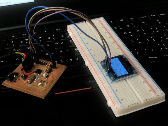
Thankfully, I had an LCD screen with I2C connection in my Arduino kit!
LCD or Liquid Crystal Display is a type of flat panel display that uses liquid crystals in its primary form of operation.
LCD usually require around 12 connections, however, IC2 connection can be established with the an add-on circuit.
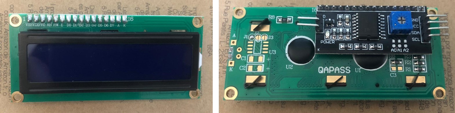
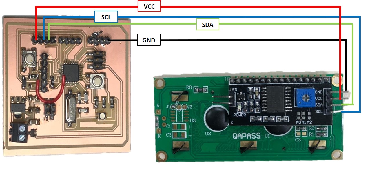
To control the LCD, I installed the latest liquid crystal library and checked the I2C address using the previously mentioned code.
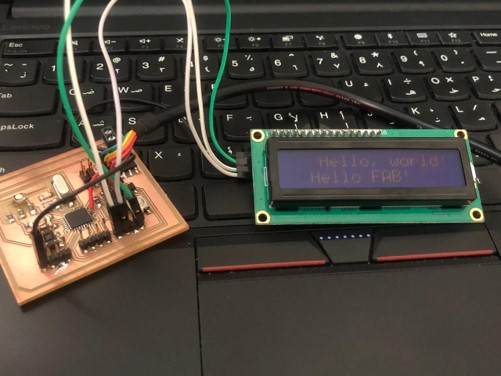
Then uploaded a simple code to test the operation.
//YWROBOT
//Compatible with the Arduino IDE 1.0
//Library version:1.1
#include <LiquidCrystal_I2C.h>

LiquidCrystal_I2C lcd(0x3F,20,4);  // set the LCD address to 0x27 for a 16 chars and 2 line display

void setup()
{
  lcd.init();                      // initialize the lcd
  // Print a message to the LCD.
  lcd.backlight();
  lcd.setCursor(3,0);
  lcd.print("Hello, world!");
  lcd.setCursor(2,1);
  lcd.print("Hello FAB!");
}


void loop()
{
}
First, the LCD didn’t show anything, even though the power light was on.
So I increased the brightness of the screen by turning the screw on the I2C add on in the back.
For the final project, I decided to use a TFT LCD screen to display a live stream of the videos and images taken by the ESP 32 cam module.
The ESP 32 cam module explained further in the input devices week, has very few GPIO pins to connect to due to the internal connections to the cam module and the SD card.
Thus, it is required that the screen I use has SPI connection.
I looked through the lab, and I found several possibly suitable screens. I decided to use the 3.5" TFT LCD shield, which had SPI connection along with an SD card reader attached.
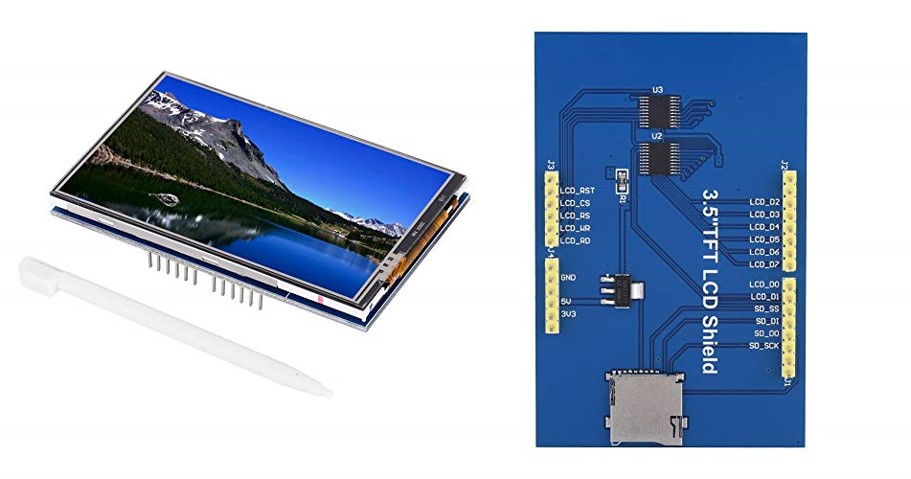
I searched for the screen datasheet, and specifications as I needed to know type of driver it had to integrate it to the ESP. Eventually I found this wiki page with the specifications, which also included the specification dataheet.
I tried to connect it to the ESP, but unfortunately it was not compatible.
Note: ESP and screen connections will be explained further below.
So with the limited time in my hands, and with the compatible screen (testimonies of several tutorials and YouTube videos) taking several weeks to arrive. I decided to base the first version of my final project on this screen.
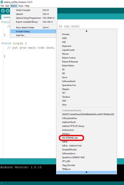
To do so, I decided to test the screen with a normal Arduino UNO. I mounted the screen on an Arduino UNO I had in hand. And searched for a suiting library. I found that screen worked best with the MCUfriend library.
I Downloaded the Zip library, and added it by going to sketch > include libraries > add .ZIP library.
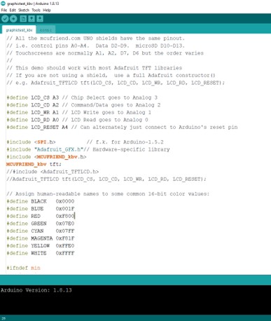
Then I uploaded one of the examples called graphic test. In the code the communication pins in the screen are specified which are:
These pins are already defined with the corresponding Arduino UNO pins, if however, another Arduino board is used (ex: MEGA, Nano) the pinout would change.
This is a ready made example that displays different shapes and fonts on the screen to test .. well.. the graphics!
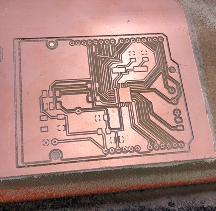
Now, that I ensured the screen worked perfectly, I needed to design my own board to mount the screen on. I decided to Design an Arduino shield that mimics an Arduino Uno.
For my first trial, I acquired a ready Arduino shield from Adafruit library in Eagle. This shield is a copy of the original Arduino but without any component and has through-hole pinheads.
Then I added the basic components for an Arduino board just as described in my electronics design week.
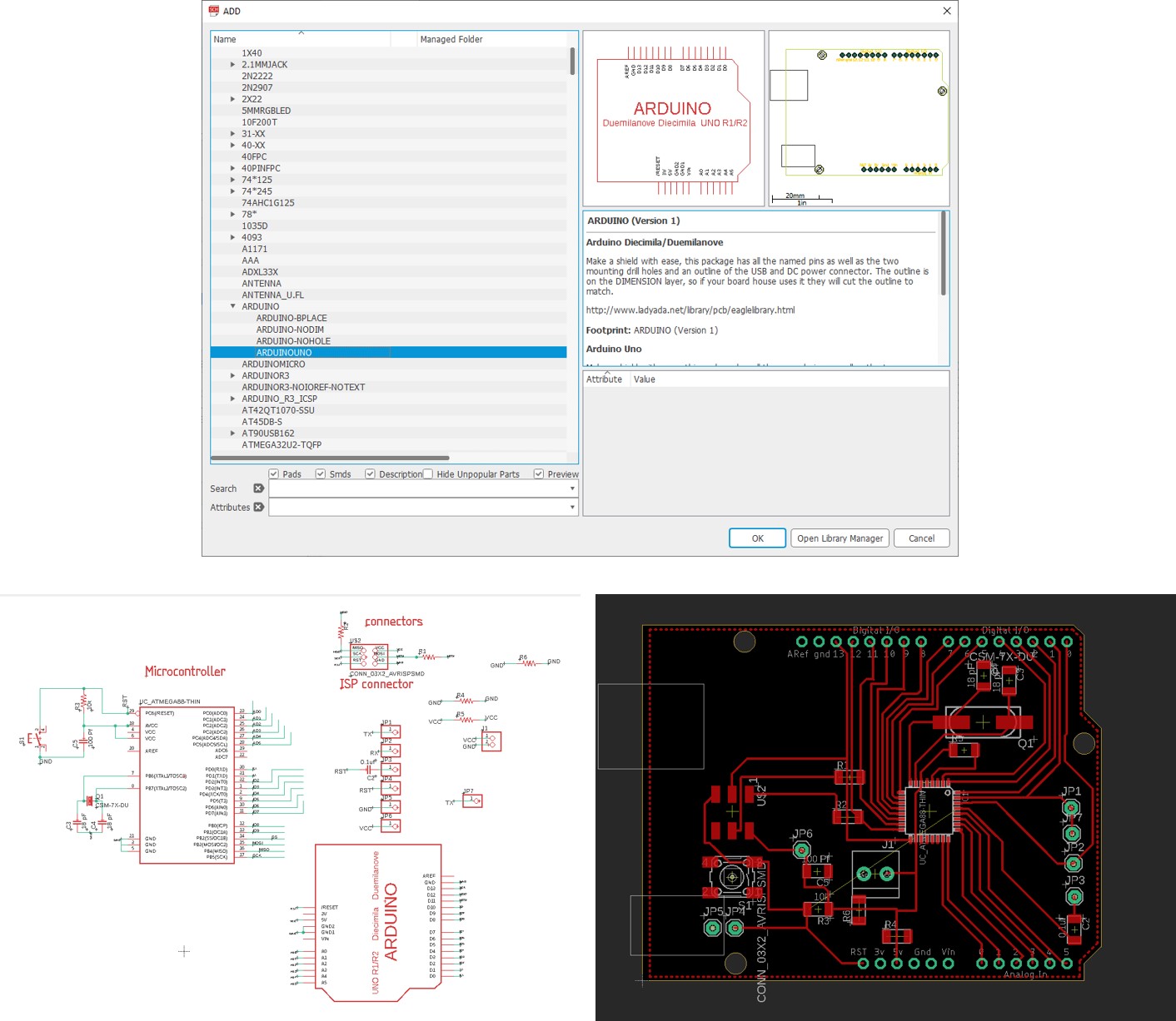
The only thing I was concerned with is the my ability to solder this efficiently, as almost all the pins on the small ATMGEA328 chip was connected to something!
The process of preparing the files and milling is explained in detail in my electronics design week.
The first milling trial didn’t go so well … :(
I didn’t check the milling bit thoroughly before milling and it turned out to be slightly broken which effected my board heavily.
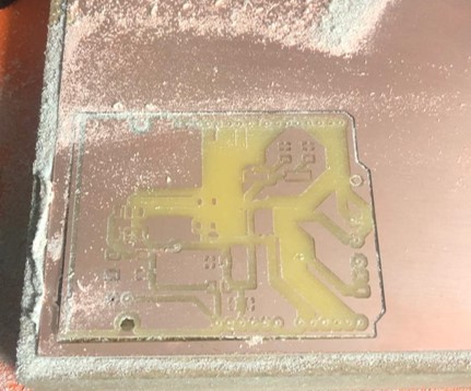
The second time milling was thankfully much better.
I soldered the components on (and as expected soldering the Atmega was exceptionally hard to do), and tried to mount the screen on!
… which very to my utmost desperation, didn’t work. I soldered the female pinheads on the back since soldering it directly on the front of the PCB was hard, and that ruined the orientation of which the screen would fix on.
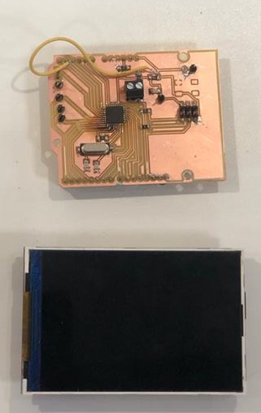
After a good rest, I decided to try again. I found another Arduino shield that had SMD female pin headers, and used that instead in Eagle. I also replaced the SMD Atmega328 with a through hole one to ease the soldering process.
My trials in the milling and soldering went as the following:.
After several trials, and a lot of frustration I managed to get one board work properly 😅.
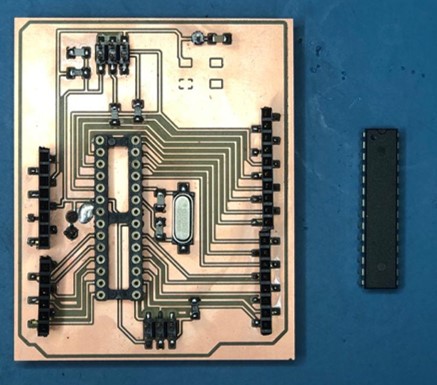
I connected it to the ISP, burned the bootloader then mounted the screen on. I re-uploaded the graphics test, and it worked perfectly.
I also tested the SD card reader at the back of the screen to display bitmap image by using one of the examples provided in the library called showBMP_kbv_Uno.
This code uses both the <SPI.h> and the <SD.h> libraries to communicate with the SD card reader.
First, I needed to save bitmap photos on the SD card to display!
This was done by googling any picture for example this one below:

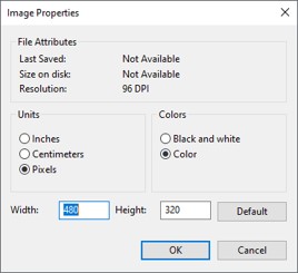
Then head to any photo editing/drawing software. I used PAINT. Import the image, and the set the properties of the page to the display size. Mine was 480 X 320 pixels.
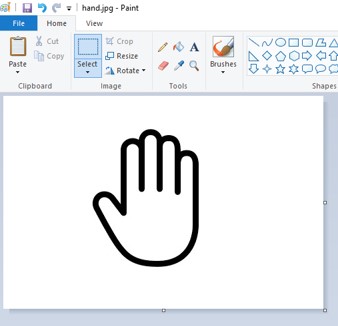
Then just save the file as a bitmap image!
or simply use an online converter.
Then save the bitmap photos on your SD card!
Back to the code, The original code goes in a loop to display All bitmap images on the SD card. What I needed is to show one image at a time. I changed the code in the void loop function to display a bitmap of the hand.
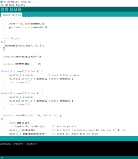
I inserted the SD card into the reader, then uploaded the code! and viola, it works!
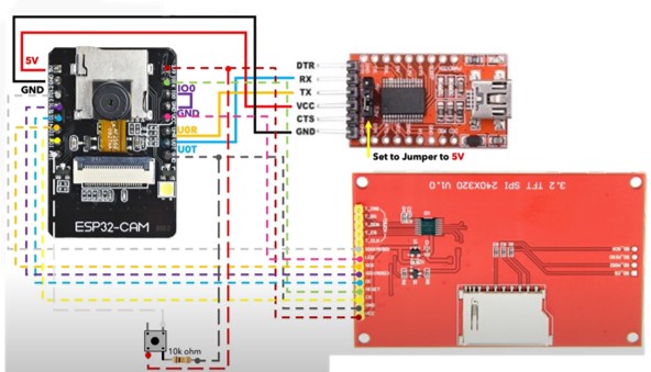
The suitable display for the ESP has finally arrived. It is the ILI9341 TFT LCD display. I can test it directly with the module to display a live steam of what the camera is capturing. The setup of the ESP 32 cam module can be found on my input devices.
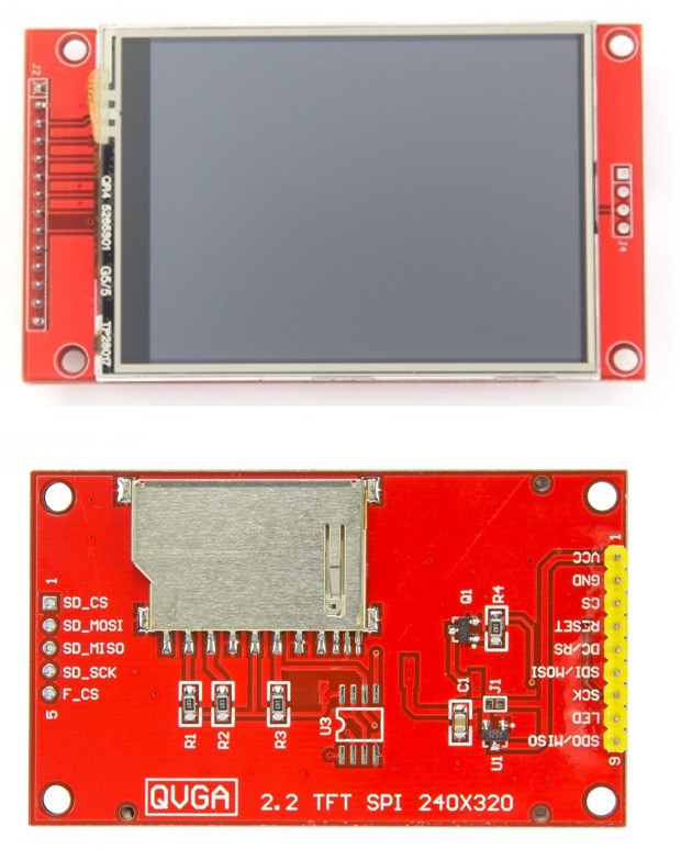
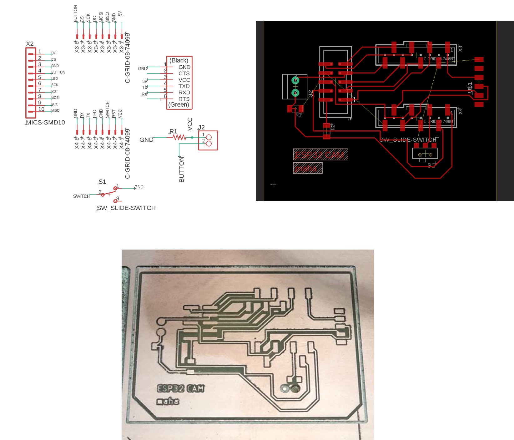
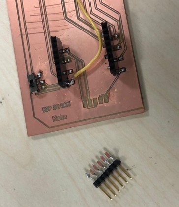
To connect the ESP module to the display efficiently, I needed to design a PCB that would reduce the large number of jumper wires required for the connection. I redesigned the PCB I used for the module in the input devices week, by adding some male headers for the screen pins.
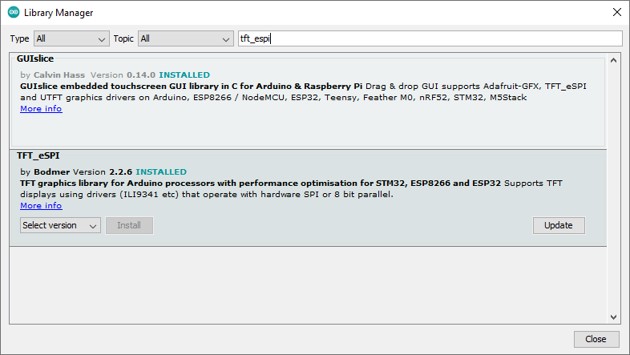
As mentioned previously, the ESP uses an SPI connection to connect to the display, therefore, a specific library is required for this connection. I installed the TFT_eSPI library from the library manager.
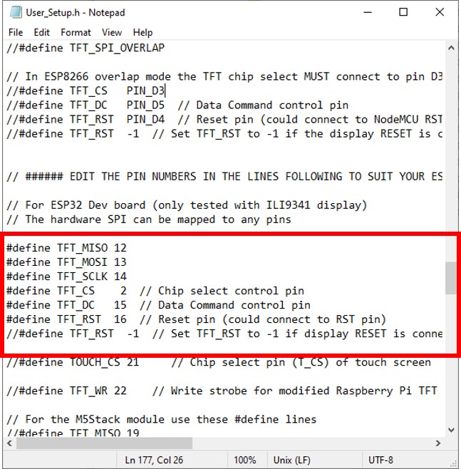
Then to connect it to the ESP, I needed to modify the setup file. I made sure that the driver set is ILI9341, uncommented the connection pins of the ESP board, and defined each pin as the following to match the pins of the ESP:
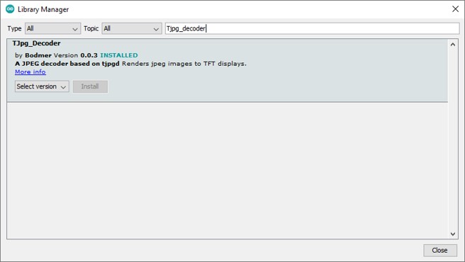
I also installed the Tjpg_decoder library to show the images into the display.
I followed this tutorial to modify the existing web camera server example of the ESP board in Arduino as such:
#include "esp_camera.h"
#define CAMERA_MODEL_AI_THINKER
#include "camera_pins.h"
#include <TJpg_Decoder.h>
#include <SPI.h>
#include <TFT_eSPI.h>


TFT_eSPI tft = TFT_eSPI();

const char* ssid = "*****";
const char* password = "******";
const unsigned long timeout = 1000; // 10 seconds

bool tft_output(int16_t x, int16_t y, uint16_t w, uint16_t h, uint16_t* bitmap)
{
   // Stop further decoding as image is running off bottom of screen
  if ( y >= tft.height() ) return 0;

  // This function will clip the image block rendering automatically at the TFT boundaries
  tft.pushImage(x, y, w, h, bitmap);

  // This might work instead if you adapt the sketch to use the Adafruit_GFX library
  // tft.drawRGBBitmap(x, y, bitmap, w, h);

  // Return 1 to decode next block
  return 1;
}


void setup() {
  Serial.begin(115200);
  delay(1000);

  Serial.println();
  pinMode(buttonPin, INPUT);

  Serial.println("INIT DISPLAY");
  tft.begin();
  tft.setRotation(3);
  tft.setTextColor(0xFFFF, 0x0000);
  tft.fillScreen(TFT_YELLOW);
  tft.setFreeFont(FSB9);

  TJpgDec.setJpgScale(1);
  TJpgDec.setSwapBytes(true);
  TJpgDec.setCallback(tft_output);

  Serial.println("INIT CAMERA");
  camera_config_t config;
  config.ledc_channel = LEDC_CHANNEL_0;
  config.ledc_timer = LEDC_TIMER_0;
  config.pin_d0 = Y2_GPIO_NUM;
  config.pin_d1 = Y3_GPIO_NUM;
  config.pin_d2 = Y4_GPIO_NUM;
  config.pin_d3 = Y5_GPIO_NUM;
  config.pin_d4 = Y6_GPIO_NUM;
  config.pin_d5 = Y7_GPIO_NUM;
  config.pin_d6 = Y8_GPIO_NUM;
  config.pin_d7 = Y9_GPIO_NUM;
  config.pin_xclk = XCLK_GPIO_NUM;
  config.pin_pclk = PCLK_GPIO_NUM;
  config.pin_vsync = VSYNC_GPIO_NUM;
  config.pin_href = HREF_GPIO_NUM;
  config.pin_sscb_sda = SIOD_GPIO_NUM;
  config.pin_sscb_scl = SIOC_GPIO_NUM;
  config.pin_pwdn = PWDN_GPIO_NUM;
  config.pin_reset = RESET_GPIO_NUM;
  config.xclk_freq_hz = 10000000;
  config.pixel_format = PIXFORMAT_JPEG;
  //init with high specs to pre-allocate larger buffers
  if(psramFound()){
    config.frame_size = FRAMESIZE_QVGA; // 320x240
    config.jpeg_quality = 10;
    config.fb_count = 2;
  } else {
    config.frame_size = FRAMESIZE_SVGA;
    config.jpeg_quality = 12;
    config.fb_count = 1;
  }


  // camera init
  esp_err_t err = esp_camera_init(&config);
  if (err != ESP_OK) {
    Serial.printf("Camera init failed with error 0x%x", err);
    return;
  }
}

camera_fb_t* capture(){
  camera_fb_t *fb = NULL;
  esp_err_t res = ESP_OK;
  fb = esp_camera_fb_get();
  return fb;
}

void showingImage(){
  camera_fb_t *fb = capture();
  if(!fb || fb->format != PIXFORMAT_JPEG){
    Serial.println("Camera capture failed");
    esp_camera_fb_return(fb);
    return;
  }else{
    TJpgDec.drawJpg(0,0,(const uint8_t*)fb->buf, fb->len);
    esp_camera_fb_return(fb);
  }
}

void loop() {

    showingImage();

}
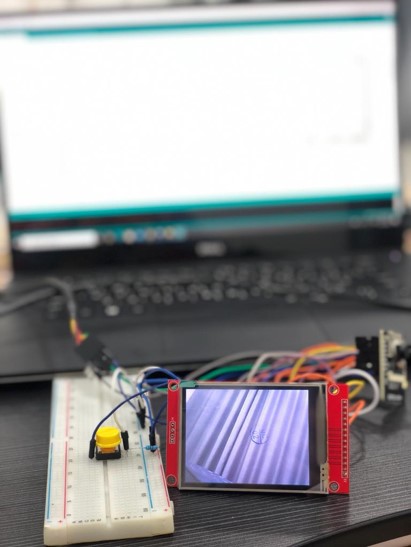
Uploaded the code to the ESP using the same steps mentioned in my input devices week, and here are the results!
unfortunately, while trying my FTDI header came off, so I used wires to try steaming the video into the screen using the exact same connection (using the PCB was much easier!)
The display shows the camera capture nicely, although the live stream might have some delay but the overall result is quite impressive!
Please find the full group assignment here.
For the group assignment, I measured the power supply for the one of the screens I used. I used the TFT LCD screen I used with my Atmega 328 board I made (ILI9486), I connected the board to the power supply and examined the change in the display brightness as I went from 3.7 V to the near maximum recommended rating 4.7 V, as the screen gets brighter as I increase the voltage.
The power supply gives a current of 0.13 A to the screen at 4.7 V. So calculating the power consumption.
Voltage = 4.7 V.
Current = 0.13 A.

P = IV = 4.7 x 0.13 = 0.611 W
