This week is all about programming!
Lets start programming!!
For the group assignment, we compared the platforms and architectures we used in this week. The page can be found here.
For this week’s task I used the Attiny 44 Hello world! and the hello.328p circuit boards that I re-designed in the electronics design week to try different programs, alongside the fabISP board I produced in the electronics production week.
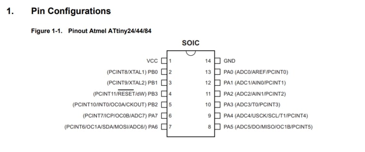
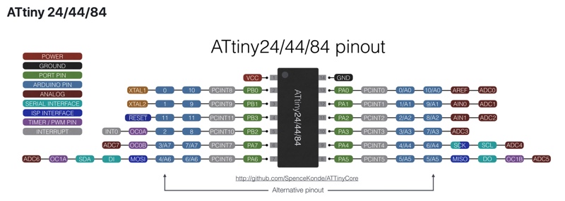
The very first step into understanding and programming the board is to look at the Attiny44 datasheet basic architecture in the datasheet.
The datasheet provides the necessary information to understand the pinout of the microcontroller chip we are using, which later would help us understand how different interfaces and tools use different pinout labels of the same microcontroller.
Another detail worth understanding before starting the programming phase is the process of which high level programming languages get “converted” or “translated” into a language understood by machines and computers.
This quick tutorial has helped me understand the process better!
In simple terms, Higher level languages such as C+ go through what’s called a pre-processor which does the basic tasks of removing comments & including header files thereby generating an intermediate file to give to the compiler, which then generates a file in assembly code (codes written in hexadecimal numbers), and sends it to the Assembler that in turn generates the object code (sets of binary numbers, 0s & 1s), finally comes the linker that links all files with the corresponding libraries into one file!
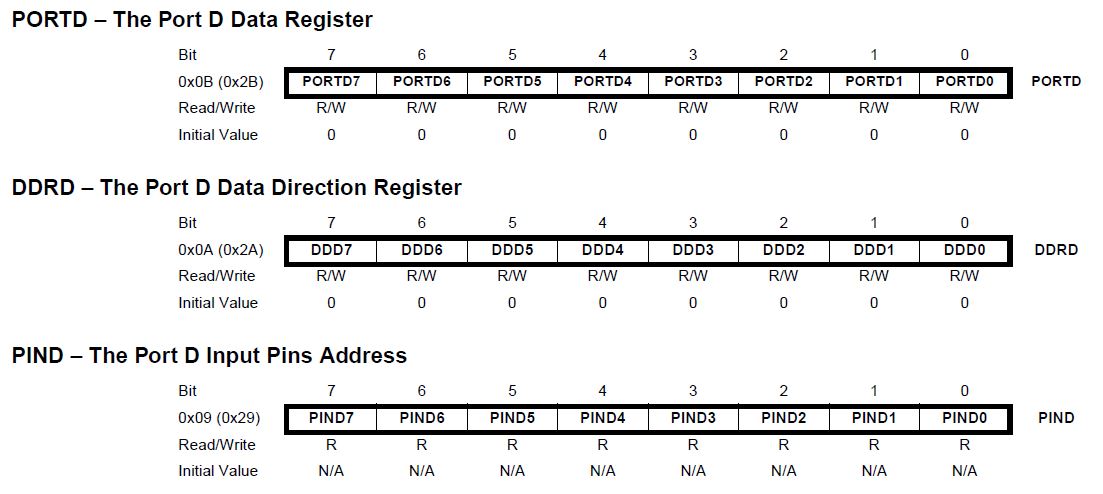
Each AVR has a certain number of ports that are not fixed in the manufacturing phase but rather configured in the programming phase.
The Atmel AVR atmega 328 is a 1 byte microcontroller. Every port in the microcontroller contains 8 bits and has 3 registers associated with each of the bits. The register bits are correlated with each of the port bits, hence bit 0 of the register is associated with pin 0 of the port.
To put it simply:
For example: * Writing PORTB pin 3 as High (setting a value of 1) = PORTB: 0b00001000
For learning and testing purposes, we initially used an Arduino Uno as a programmer. The microcontroller built in Arduino Uno is the Atmega 328p, which is an 8-bit AVR microcontroller.
The very first environment I used is called CodeBlocks which is an open source platform with support to a variety of compilers, along with Freematics builder which aids integrating toolchains and libraries and uploading to the Arduino Board.
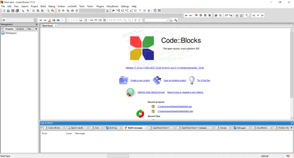
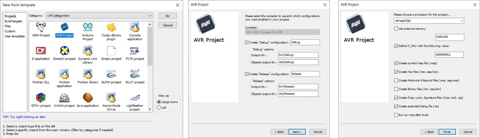
To start off, I created a new project in code blocks by accessing the file tab, Next, chose AVR projects, then enter the project name and change the directory, I followed the few next steps without changing any default settings, then made sure to choose ATmega 328p when asked for the processor.
And wrote a simple code to blink the LED in the Arduino board.
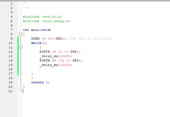
/*
*/
#include <avr/io.h>
#include <util/delay.h>
int main(void)
{
DDRB |= (1<<PB5);//SET LED PB5 as an output
while(1)
{
PORTB |= (1 << PB5);//Turns LED on
_delay_ms(1000);// Delay for 1 sec
PORTB &= ~(1 << PB5);// Turns LED off
_delay_ms(1000);/// Delay for 1 sec
}
;
return 0;
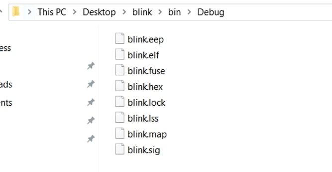
}Then clicked on build icon, which processes and compiles the file, creating a .hex file to run on the assembler tool.
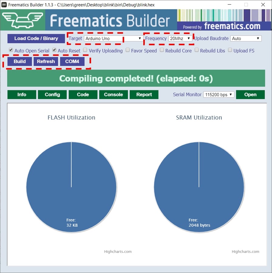
I then opened freematics builder, uploaded the blink.hex file, and selected Arduino UNO as my board type. I clicked on refresh to select the Port connected and finally build. The monitor showed me that the code has been uploaded, and the LED started blinking!
For this part I used Yosuke Tsuchiya’s work as a reference.
First, I opened the makefile in notepad and edited so the F_CPU frequency is 200000, and the programmer I am using is Atiny44.
PROJECT=blink
SOURCES=$(PROJECT).c
MMCU=attiny44
F_CPU = 20000000

CFLAGS=-mmcu=$(MMCU) -Wall -Os -DF_CPU=$(F_CPU)

$(PROJECT).hex: $(PROJECT).out
    avr-objcopy -O ihex $(PROJECT).out $(PROJECT).c.hex;\
    avr-size --mcu=$(MMCU) --format=avr $(PROJECT).out

...
Next, I created another notepad file to write my C code in it, and saved it as blink.c. This is a simple code to blink the LED on my hello.44 board.
#include <avr/io.h>
#include <util/delay.h>

int main(void){

 DDRA |= (1<<PA3); // sets LED as output

  while(1){

    PORTA |= (1 << PA3);// turns LED on
    _delay_ms(1000);
    PORTA &= ~(1 << PA3);// turns LED off
    _delay_ms(1000);
}
}
Next, I opened git bash and typed the following commands to create the hex files and push the code to the board:
$ make -f makefile
$ make -f makefile program-usbtiny-fuses
$ make -f blink program-usbtiny
To program my boards using the FabISP I used Aduino IDE environment. However, I needed to install the Attiny44 package on the Arduino software first. I followed the steps in the tutorial to copy the package URL and add it in my Additional Board Manager under Preferences.
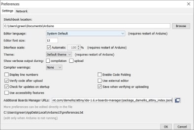
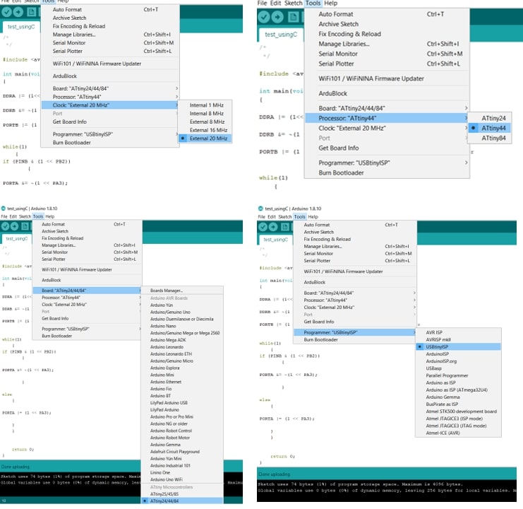
I then headed to the library manager and checked for the package and installed it. Later, I chose the relative options for board, processor, clock and programmer.
And finally I attached my FabISP and clicked on burn bootloader. Instantly an Error message popped out.
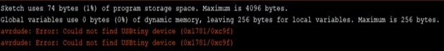
The only thing I could imagine went wrong was the AVRDUDE in my laptop hence I had some issues with it previously. However, with the help of Hashim, it turned out that the issue was with my hello world board about to be programmed was with the physical connection. As it turns out, there was a slight short with one of my resonator pins and the reset pin, thus halting the burn process.
Fixing the soldering, I went on and ran the bootloader and then uploaded the code we wrote in C using upload using programmer.
The following code is used to Turn ON the LED when the BUTTON is pressed and Turning off the LED when the button is released.
/*
 * The following code was written by Hashim Al Sakkaf, my modified version of it includes the pins I set for my button and LED.
 * The code below is used to Turn on the LED once the button is pressed, and Turn off the LED once the button is released. The light emitting diode is used here to test the proper
 operation of the button and the pull up resistor.
 * The button is connected to physcial pin number 5, which corrosponds to pin 2 in port B (PB2)
 * The LED is connected to physical pin 3, which corrosponds to Pin 3 in port A (PA3)
 */

#include <avr/io.h> // The library used to pull AVR commands.

int main(void)
{
DDRA |= (1<<PA3);//Sets  PA3 = LED as OUTPUT
DDRB &= ~(1 << PB2); //sets PB2 = BUTTON as input
PORTB |= (1 << PB2); // activates the button's internal resistor, hence the button having logic 1.
while(1)
    {
if (PINB & (1 << PB2)) // checks if the button has logic 1 (HIGH, not pressed)
  {
PORTA &= ~(1 << PA3);// turn off the LED (logic 0)
  }
else
  {
PORTA |= (1 << PA3);// turn on the LED (logic)
  }
  }
return 0;
}
In the code above, I used logic gates to program the ports hence its easier and faster.
Logic gate OR returns a high value (logic 1) when any of the inputs is high. ex: PORTB |= (1<<PB2) 1 (high) ORed with 0 (low) gives us 1, thus setting the port as an output.
Logic gate AND returns a high value (logic 1) only if all inputs are high. ex: PORTA &= ~(1 << PA3) 1 (high) ANDed with 0 (low) gives the port logic 0.
Arduino language is set based on C & C++ commands, however made to be easier to handle. I used Arduino language to program my board to perform the same operation as previously described.
This time however, we used the Arduino pin numbers to set the pins for the LED and the Button.
/*
 * The code below is used to Turn on the LED once the button is pressed, and Turn off the LED once the button is released. The light emitting diode is used here to test the proper
 operation of the button and the pull up resistor.
 * The button is connected to physicals pin number 5, which corresponds to pin 2 in port B (PB2)
 * The LED is connected to physical pin 3, which corresponds to Pin 3 in port A (PA3)

 */

// initialize constant pins.
const int button = 8;
const int led = 3;

// initialize variable pins
int ButtonState = 0;

void setup() {
pinMode(led,OUTPUT);//sets pin 3 (LED) as output
pinMode(button,INPUT);// sets pin 8 (button)
digitalWrite(button,HIGH); // writes the button as high (logic 1) activating the internal pull up resistor.
}

void loop()
{
 ButtonState = digitalRead(button);// reads the button state
 if (ButtonState == HIGH) // checks if the button state is high (released)
 {
  digitalWrite(led,LOW);// if the button state is high, then the LED is turned off
 }
 else
 {
  digitalWrite(led,HIGH); // if the button is low (pressed), then turn on the LED.
 }
}For this part, I went on and used Abdulla Alhamad page as a reference for the operation of the Ardublocks tool.
I installed the .jar Ardublocks package, and followed the installation guide.
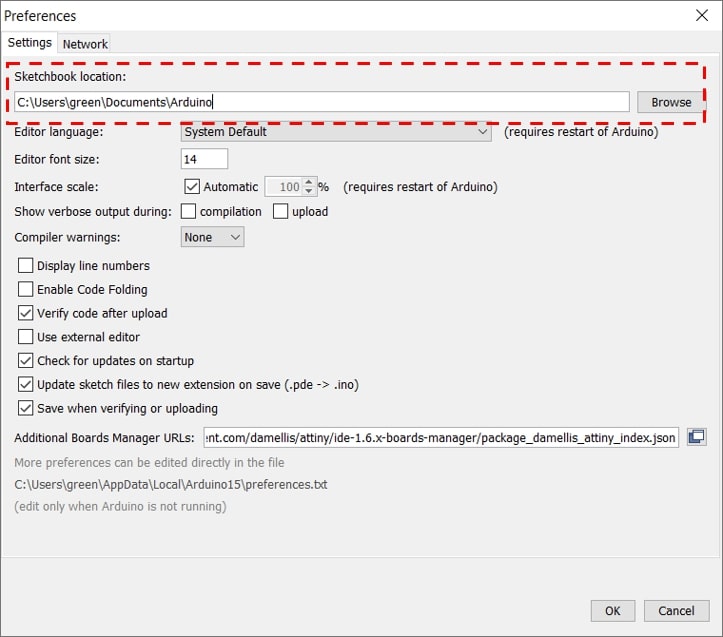
First, I checked my sketchbook location by going to file tab >> preferences in the Arduino software. The default sketchbook location in my laptop is C:\Users\green\Documents\Arduino. This is where my Ardhublocks tool package will be copied to.
Next, I navigated to the default sketchbook location and created my folders. I got a bit stuck on this step, creating folders, renaming them and failing one time after another to launch the tool in IDE.
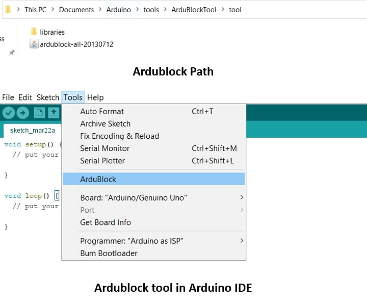
Lesson learned: create your folder in this exact order and sytax, hence the tool and folders created are extremely case sensitive:
C:
I copied and pasted the package in my folder, and restarted Arduino IDE. Then I went to the tools tab and under it, the tool was there!
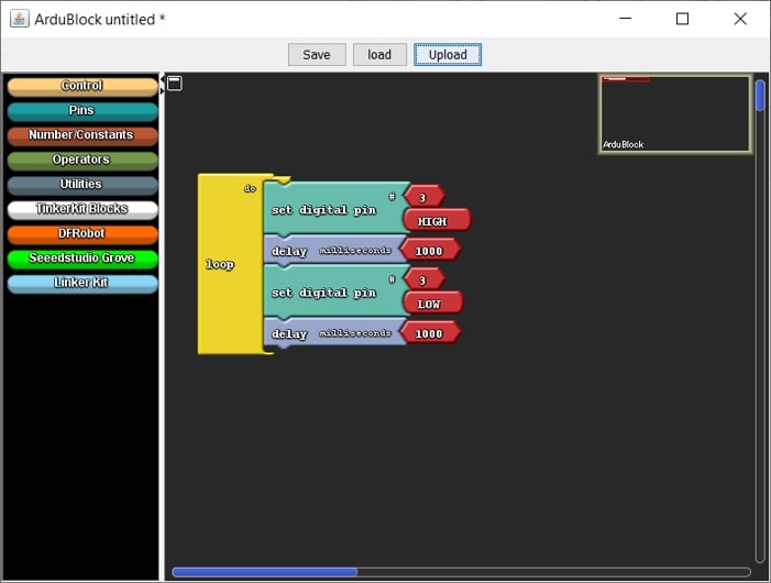
I launched the tool, and began my exploration. On the first impression, it looked like the tool my 11 year old sister would use for her python class. The familiarity of the tool made it easier to work with, the tool uses the drag and drop method to select different blocks and use them as commands.
I wanted to test the tool first so I went on with a simple blink program!
And tried to upload the code to my Arduino board. However, an error message popped out.
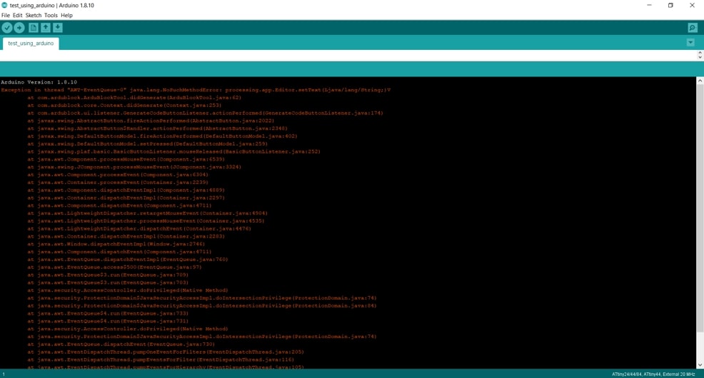
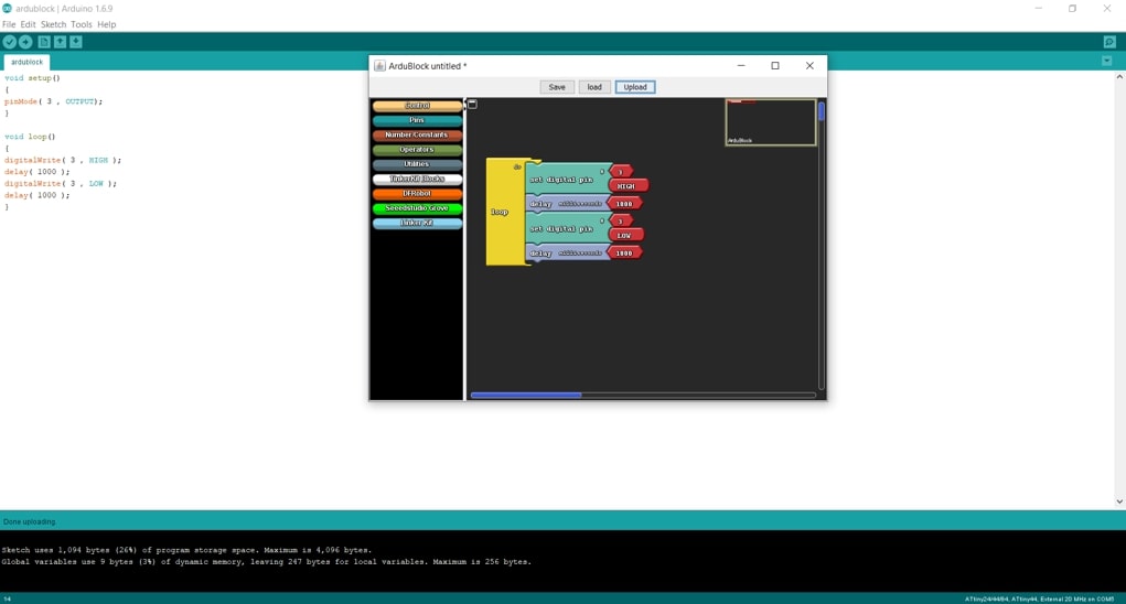
After searching on the web, it turned out that the tool is not really compatible with the Arduino software version I’m using (Arduino 1.8.10), So I tried with another version (Arduino 1.6.9) with hopes that it would work!
I retried the blink program I created and it worked this time!
Once the blocks are created and the upload button is pressed, the tool converts the blocks into arduino commands, compiles and uploads.
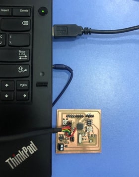
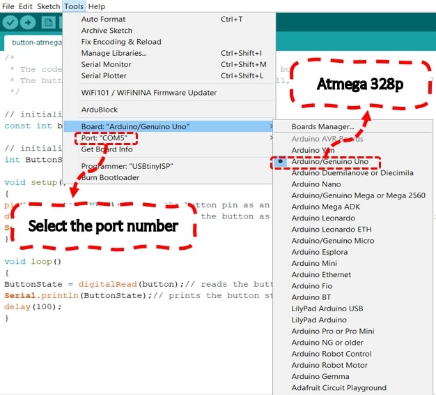
I also tested some simple codes on the Atmega 328 board I designed on the electronics design week. First, I had to burn the booloader on the atmega 328 to be able to program it and use it as an arduini UNO. To do so, I connected the board to my Fab ISP through a ribbon, connected it to the laptop, and opened Arduino IDE. I went to tools >> selected the board Arduino UNO >> selected the programmer USB tinyISP>> and finally clicked on burn bootloader.
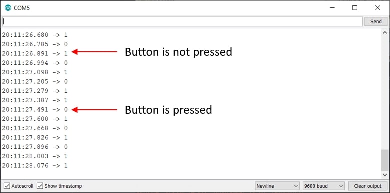
First I had to check my connection to the board using the FTDI cable. I used Arduino IDE as the environment to test on. I wrote a simple code to test the button on my board, and print it’s status on the serial monitor.
/*
 * The code below is used to test the button on the board.
 * The button is connected to physicals pin number 11, which corresponds to pin 7 in port D (PD7)
 */

// initialize constant pins.
const int button = 7;

// initialize variable pins
int ButtonState = 0;

void setup()
{
pinMode(button,INPUT);// sets the button pin as an output
digitalWrite(button,HIGH); // writes the button as high (logic 1) activating the internal pull up resistor.
Serial.begin(9600);
}

void loop()
{
ButtonState = digitalRead(button);// reads the button state
Serial.println(ButtonState);// prints the button state on the serial monitor.
delay(100);
}
When I tried compiling and uploading the code, this following error message popped. The programmer was not responding as connection was not stable. So the error had to be in the FTDI connection.
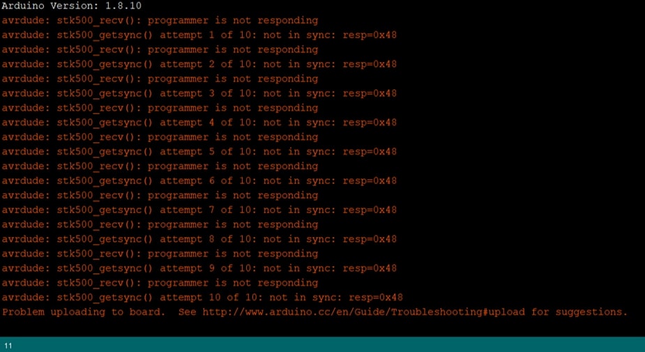
I tested the connection between the transmitter and the receiver pins in the FTDI header and the atmega 328 chip using the multimeter, and the connection was right. Convinced that the error was still related to the physical connection I tested the rest of the pins, and found a very small amount of solder connecting the reset pin of the FTDI and the common ground causing a short circuit.
Extra soldering removed, I tried compiling uploading the code again, and the Ftdi was able to communicate with the atmega chip. The serial monitor displays 1 or high when the button is not pressed (hence the pull up resistor is high), and 0 or low when the button is pressed.
Next I tried testing the RGB LED on the board. I wrote a simple code that consisted of testing each color on it’s own. I used the LED pins as digital Outputs here hence I was just testing its operation first.
//initialize LED pins

int red = 6;
int green = 5;
int blue = 3;


void setup() {
  //sets pins as outputs
pinMode(red,OUTPUT);
pinMode(green,OUTPUT);
pinMode(blue,OUTPUT);
}

void loop() {

//BLUE
digitalWrite(red,LOW);
digitalWrite(green,LOW);
digitalWrite(blue,HIGH);
delay(1000);

//RED
digitalWrite(red,HIGH);
digitalWrite(green,LOW);
digitalWrite(blue,LOW);
delay(1000);

//GREEN
digitalWrite(red,LOW);
digitalWrite(green,HIGH);
digitalWrite(blue,LOW);
delay(1000);
}
However, the RGB colors were off. Instead of showing blue, green and red, it showed yellow, purple and magenta.
Checking the RGB LED datasheet, I discovered that the LED I was using was a common anode RGB. To program the common anode RGB, the state of the color displayed should be low while the rest are high.
Trying the code again after fixing it.
//initialize LED pins

int red = 6;
int green = 5;
int blue = 3;


void setup() {
  //sets pins as outputs
pinMode(red,OUTPUT);
pinMode(green,OUTPUT);
pinMode(blue,OUTPUT);
}

void loop() {

//BLUE
digitalWrite(red,HIGH);
digitalWrite(green,HIGH);
digitalWrite(blue,LOW);
delay(1000);

//RED
digitalWrite(red,LOW);
digitalWrite(green,HIGH);
digitalWrite(blue,HIGH);
delay(1000);

//GREEN
digitalWrite(red,HIGH);
digitalWrite(green,LOW);
digitalWrite(blue,HIGH);
delay(1000);
}
For the RGB LED the number of possible color combinations is very high:
If an RGB is used, the range of colors is 0-255. Meaning there are 256 possible values for each Red, Green and Blue. 256^3 is 16,777,216.
And by using a simple color picker, we can get the RGB value ranges for every possible color!
Thus trying the color combinations. For this code, I used the analogWrite since the RGB pins are connected to PWM pins in the atmega 328. This means that the changing the values frm 0 (representing 0 volts) to 255 (maximum voltage 5 volts) changes the brightness of the LED accordingly. Consequently, using different combinations of the RGB values produces new colors.
//initializes Pins
int redPin = 6;
int greenPin = 5;
int bluePin  = 3;


void setup()
{
  // Sets LED pins as outputs
  pinMode(redPin, OUTPUT);
  pinMode(greenPin, OUTPUT);
  pinMode(bluePin, OUTPUT);
}

void loop()
{
  Colors(255, 0, 0);  // red
  delay(1000);
  Colors(0, 255, 0 );  //green
  delay(1000);
  Colors(0, 0, 255);  // blue
  delay(1000);
  Colors(255, 20, 147); // Deep pink
  delay(1000);
  Colors(255, 255, 0);  // yellow
  delay(1000);
  Colors(250, 128, 114); // Salmon
  delay(1000);
  Colors(255, 255, 255);  // white
  delay(1000);
  Colors(0, 255, 255);  //cyan
  delay(1000);
  Colors(255, 0, 125); // Magenta
  delay(1000);
  Colors(0, 128, 128); // teal
  delay(1000);
  Colors(255, 165, 0); // Orange
  delay(1000);
  Colors(75, 0, 130); // Indigo
  delay(1000);
  Colors(192, 192, 192); //Silver
  delay(1000);
}

// Function to set write the color values
void Colors(int red, int green, int blue)
{
  red= 255 - red;
  green = 255 - green;
  blue = 255 - blue;
  analogWrite(redPin, red);
  analogWrite(greenPin, green);
  analogWrite(bluePin, blue);
}
XOD IDE pronounced ZOD, is an open source visual programming environment that enables programming using blocks and nodes.
I used this tutorial to learn more about XOD.
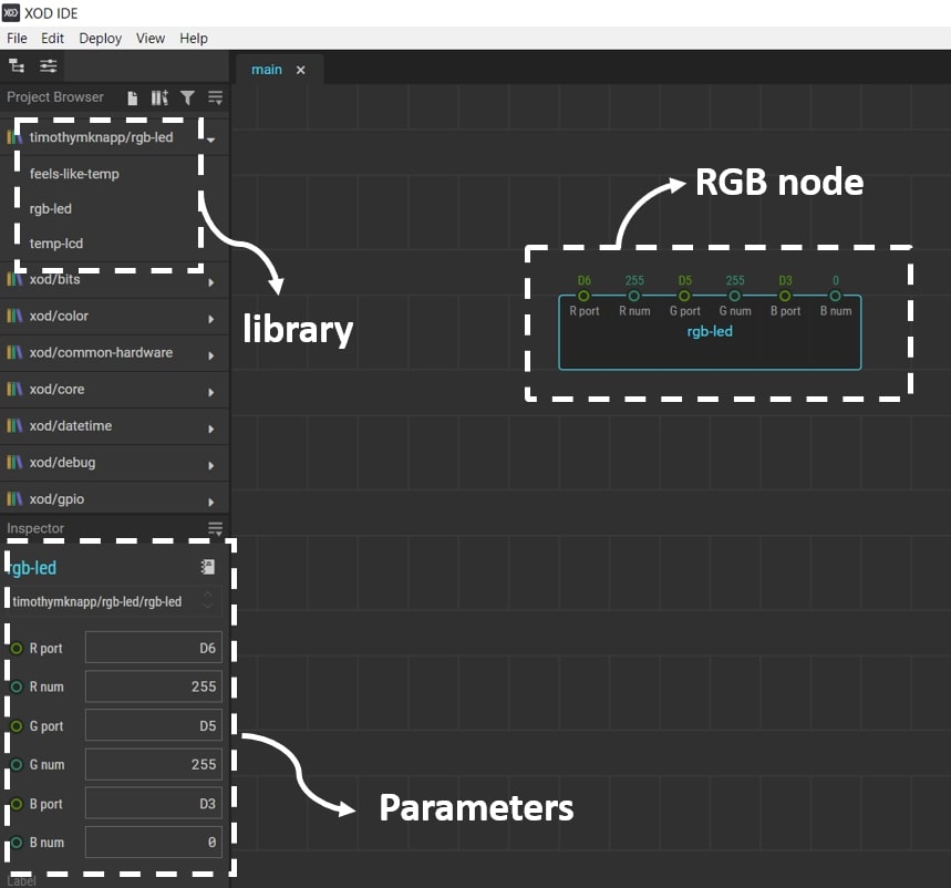
XOD uses visual objects called nodes, which are small blocks with little circles. Each circle represents pins for connections. The pins on the top represent are the inputs for the block while the bottom pins are the output of the block.
I decided to create a simple code to turn one of the colors on my RGB led, however, upon searching the libraries I did not find a block for the RGB led. But, as XOD is an opensource environment, there were a lot of personal effort libraries to look at and consider.
I added the RGB LED library to my software, and dragged and dropped the block into my working space, then I clicked on the block to change the parameters and the port numbers.
Next I head to deploy >> Upload to Arduino. A window will pop-up where I can check my board model and the port connection, and then I clicked on upload.
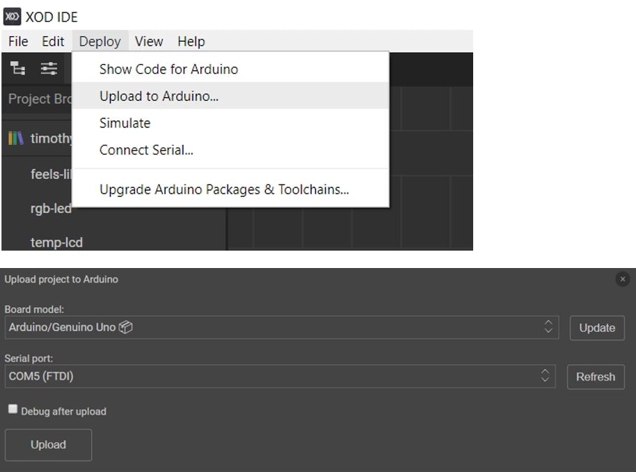
The program would then compile and upload the code to the atmega board.
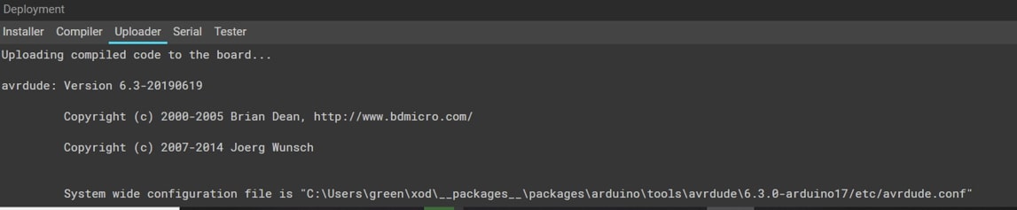
And according to my block, the RGB should be turning blue, and it worked!
PlatformIO is a cross-platform, cross-architecture, multiple framework, professional tool for embedded systems engineers and for software developers who write applications for embedded products.
To start working on platform IO, the package needs to be installed and built on carrier platform. The tool can be installed on atom or Vscode.
I chose to install it on Vscode because I wanted to try the platform! Visual Studio Code is a lightweight but powerful source code editor which runs on your desktop and is available for Windows, macOS and Linux. It comes with built-in support for JavaScript, TypeScript and Node.js and has a rich ecosystem of extensions for other languages (such as C++, C#, Java, Python, PHP, Go) and runtimes (such as .NET and Unity).
After installing Vscode, I followed the tutorial to install platformIO. Contrary to what I initially thought, I was happy to see that the whole process was quite quick and easy!
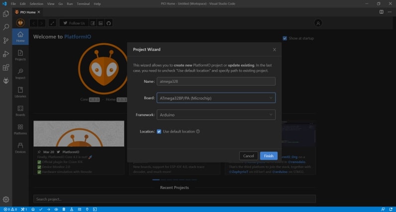
Then I opened a new project and chose the board I would like to work on.
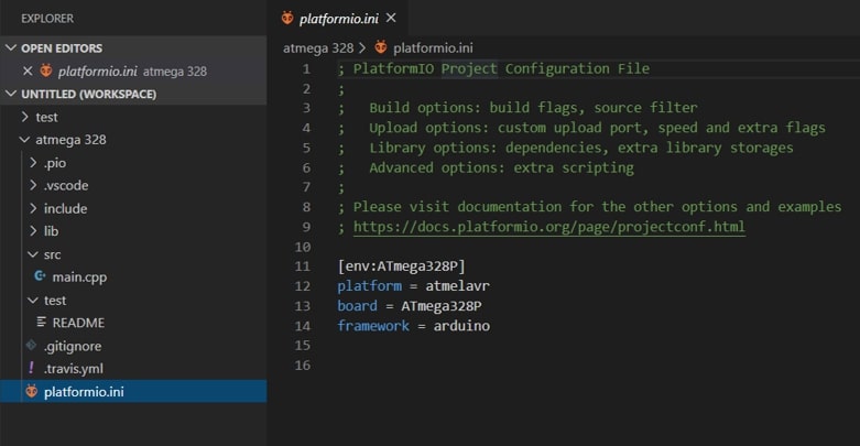
upon creating the project, the platformio.ini is created which contains the configuration for the board I am using.
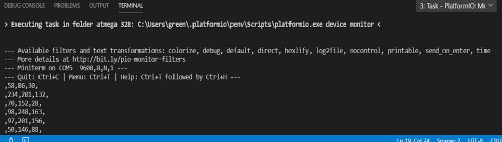
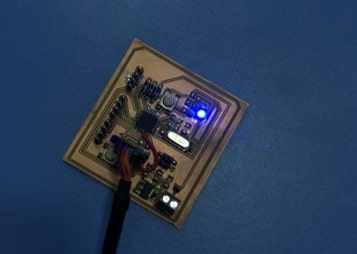
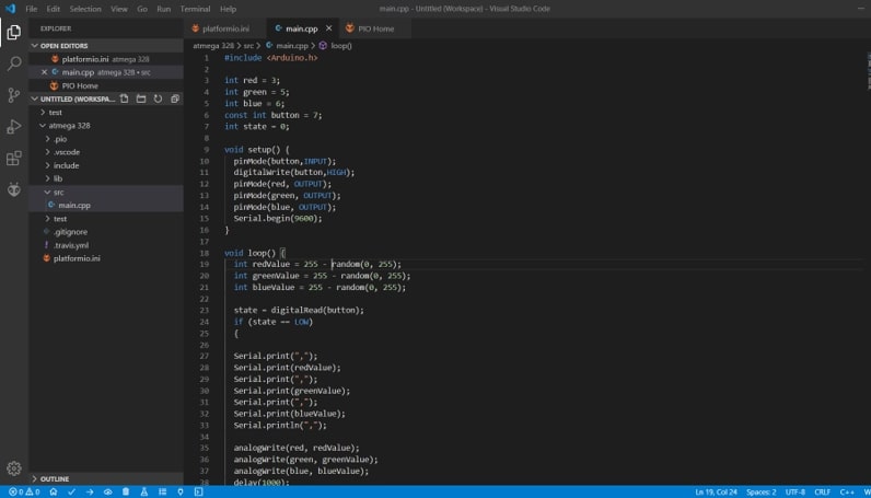
Then I accessed the main.cpp file under SRC to write my code. This code generates a random RGB color every time the button is pressed, and writes the randomly generated values on the serial monitor.
#include <Arduino.h>

// Initializes Pins
int red = 3;
int green = 5;
int blue = 6;
const int button = 7;
int state = 0;


void setup() {
  //sets button as input and activates pull up resistor.
  pinMode(button,INPUT);
  digitalWrite(button,HIGH);

  //sets RGB pins as outputs
  pinMode(red, OUTPUT);
  pinMode(green, OUTPUT);
  pinMode(blue, OUTPUT);

// Initilizes serial monitor
  Serial.begin(9600);
}

void loop() {
  // Generates random values for each color.
  int redValue = 255 - random(0, 255);
  int greenValue = 255 - random(0, 255);
  int blueValue = 255 - random(0, 255);

  // reads s the button state
  state = digitalRead(button);

  // if the button is pressed then the following commands are executed
  if (state == LOW)
  {
  // Prints the randomly generated values in the serial monitor in one line.
  Serial.print(",");
  Serial.print(redValue);
  Serial.print(",");
  Serial.print(greenValue);
  Serial.print(",");
  Serial.print(blueValue);
  Serial.println(",");

  // Sets the RGB LED with the generated values.
  analogWrite(red, redValue);
  analogWrite(green, greenValue);
  analogWrite(blue, blueValue);
  delay(1000);
}
}
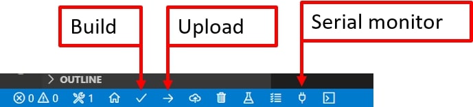
Then I clicked on the bottom tool bar for the build and uplaod.
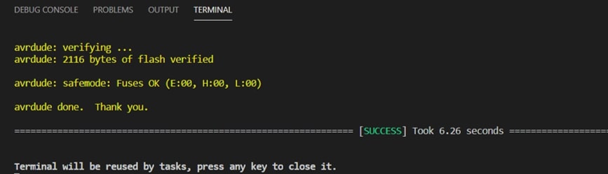
The code was uploaded successfully, and the serial monitor is showing new values for each time the button is pressed.