Probe an input device(s)’s analog and digital signals
Document your work (in a group or individually)
This is the third week of distance-working on our Fab Academy assignments. Due to my limited resources at home I was not able to produce an input board for this week (I’ll be designing one on eagle, produce it and program it as soon as we return), however, I did have an old Arduino Uno Kit full of sensors I can use for this week (lucky me!).
So for this week these are my personal goals:
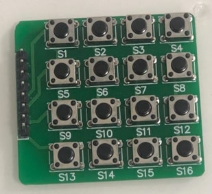
The first input I am reading this week is a Hex 4X4 keypad that came with the Arduino UNO kit. The hex keypad I am using this week is a simple no-name keypad with push buttons.
Hex keypads typical applications range from code locks, calculators, automation systems, or simply any operation that requires a character or numeric input value.
A Hex (or a matrix) 4X4 keypad is simply an arrangement of 16 push buttons in a 4X4 matrix form. The keypad has 4 rows (R1, R2 , R3, R4) and 4 columns (C1, C2, C3, C4). At each intersecting point of the rows and columns there is a switch, thus creating a combination of 16 switches (or inputs).
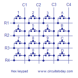
To detect a pressed key, the program does a method called column scanning:
Set the column pins as inputs, and the rows pins as outputs.
Connect the input pins to pull up resistors (alternatively use the internal pull up of the Arduino) to keep the state of the columns as HIGH.
The microcontroller sends LOW to each row at a time keeping the other rows HIGH.
The microcontroller then checks the logic status of each column on that particular row, if there is a LOW signal detected on the column this means that the push button is pressed.
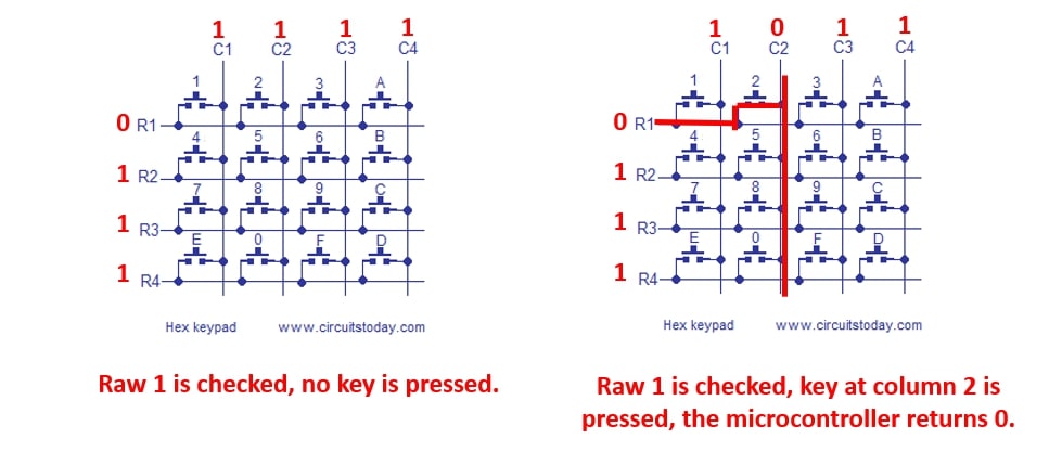
Extra explanation:
Since the column is an input pin and is pulled up HIGH internally, no pressed button would return 1 to the microcontroller. When the button is pressed it’s status now becomes 0, and both the row and the column are now connected (or short).
To identify which pins are the input pins (column) and which are the output pins on the keypad, I observed the traces that connect the pin headers to each row and column.
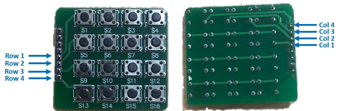
Then I connected The keypad to the Arduino Uno board and tested the code below:
// This code was fetched from http://www.circuitstoday.com/interfacing-hex-keypad-to-arduino and modified by Maha for fab Academy 2020.

int row[]={5, 4, 3, 2};// Defining row pins of keypad connected to Aeduino pins
int col[]={6, 7, 8, 9};//Defining column pins of keypad connected to Arduino
int i,j; // Two counter variables to count inside for loop
int col_scan; // Variable to hold value of scanned columns
void setup()
{
Serial.begin(9600);
for(i=0;i<=3;i++)
{
pinMode(row[i],OUTPUT); // sets the row pins as digital outputs
pinMode(col[i],INPUT); // sets the column pins as digital inputs
digitalWrite(col[i],HIGH);// activates the pull up resistor for the columnns.
} }
void loop()
{
for(i=0; i<=3; i++) // digital writes LOW to a row at a time.
{
digitalWrite(row[0],HIGH);
digitalWrite(row[1],HIGH);
digitalWrite(row[2],HIGH);
digitalWrite(row[3],HIGH);
digitalWrite(row[i],LOW);
for(j=0; j<=3; j++) // scans the columns in that particular row.
{
col_scan=digitalRead(col[j]);
if(col_scan==LOW) // if the column is pressed (LOW) the perform the keypress function.
{
keypress(i,j);
delay(300);
}}
}}
void keypress(int i, int j)
{
if(i==0&&j==0)
Serial.println("1"); // if the key at the first column in the first row is pressed, then it has the value of 1.
if(i==0&&j==1)
Serial.println("2");
if(i==0&&j==2)
Serial.println("3");
if(i==0&&j==3)
Serial.println("A");
if(i==1&&j==0)
Serial.println("4");
if(i==1&&j==1)
Serial.println("5");
if(i==1&&j==2)
Serial.println("6");
if(i==1&&j==3)
Serial.println("B");
if(i==2&&j==0)
Serial.println("7");
if(i==2&&j==1)
Serial.println("8");
if(i==2&&j==2)
Serial.println("9");
if(i==2&&j==3)
Serial.println("C");
if(i==3&&j==0)
Serial.println("*");
if(i==3&&j==1)
Serial.println("0");
if(i==3&&j==2)
Serial.println("#");
if(i==3&&j==3)
Serial.println("D");
}
Alternatively, I installed the keypad library by Mark Stanley and Alexander Brevig by going to sketch tab >> include library >> manage libraries.
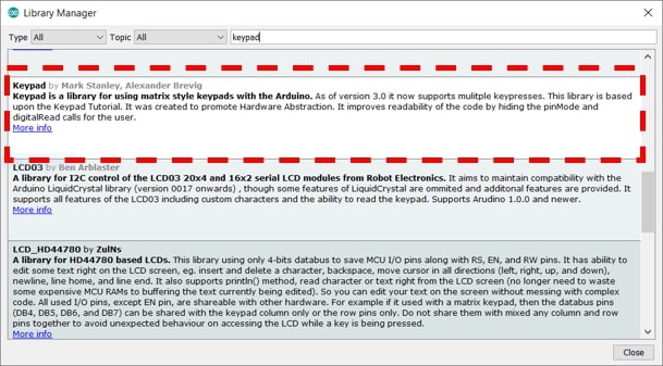
This library uses commands to execute the code in an easier, and much neater way.
/* @file CustomKeypad.pde
|| @version 1.0
|| @author Alexander Brevig
|| @contact alexanderbrevig@gmail.com
|| @description
|| | Demonstrates changing the keypad size and key values.
|| Modified by Maha for Fab Academy 2020. Changed the Pin numbers, and altered the HexKeys for experimentation.
*/
#include <Keypad.h>

const byte ROWS = 4; /* four rows */
const byte COLS = 4; /* four columns */
/* define the symbols on the buttons of the keypads */
char hexaKeys[ROWS][COLS] = {
  {'0','1','2','3'},
  {'4','5','6','7'},
  {'8','9','A','B'},
  {'C','D','E','F'}
};
byte rowPins[ROWS] = {5, 4, 3, 2}; /* connect to the row pinouts of the keypad */
byte colPins[COLS] = {6, 7, 8, 9}; /* connect to the column pinouts of the keypad */

/* initialize an instance of class NewKeypad */
Keypad customKeypad = Keypad( makeKeymap(hexaKeys), rowPins, colPins, ROWS, COLS);

void setup(){
Serial.begin(9600);
}

void loop(){
  char customKey = customKeypad.getKey(); // reads column and the rows of the keypad

  if (customKey){
Serial.println(customKey);
  }
}
Both of the codes yielded the same results.
The second sensor I tried this week is a light sensor. I wanted to use a photo-transistor, but unfortunately (or fortunately?) I only had an LDR available at the moment. To test this sensor, I am using the Atmega 328 board that I created back in the Electronics design week.
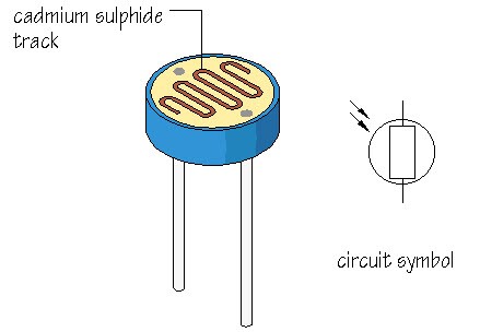
Light dependent resistors or photo resistors , are components with variable resistance that changes based on the light intensity that falls upon its surface. Usual applications for this type of sensor is for operations that require sensing the presence of light, for example automated street lights!
The LDR works on the principles of photo-conductivity, when light falls on the LDR, the resistance decreases, and the resistance increases back in the dark.
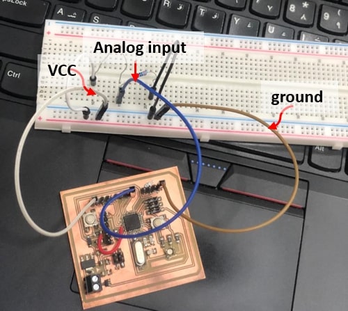
I used an LDR, A 100 K-ohm resistor, a breadboard, some jumper wires, an FTDI cable and of course the atmega board.
I connected one leg of the LDR to the VCC (5V) pin, and the other to the analog pin 0. The 100K resistor is also connected to the later leg, and grounded.
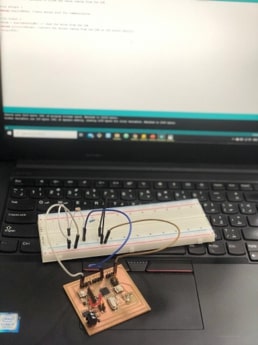
And tested a simple code to read the values of the LDR. Here we’re reading the analog voltage coming out of the LDR when its connected to VCC. The higher the intensity of the light, the greater the corresponding voltage will be.
The analog to digital converter pin will convert the analog voltage (0 - 5V) to digital values in the range of (0-1023).
int LDR = A0; // sets the Analog Pin for the LDR
int Value = 0; // variable to store the value coming from the LDR

void setup() {
Serial.begin(9600); //sets serial port for communication
}
void loop() {
Value = analogRead(LDR); // read the value from the LDR
Serial.println(Value); //prints the values coming from the LDR on the serial Monitor
delay(300);
}
I tested the LDR in normal room light and with the lights switched off. When the lights were switched off the readings went straight to 0, and the highest reading I had in normal light was around 250. However, when I directed the flashlight of my phone on the LDR the readings went as high as 600.
I also observed the LDR readings, exposing it to flashlight when the lights were switched off, and covering the LDR when the lights were initially ON.
Then I modified the code, just so when the intensity of the light is below a certain level, the RED of the RGB I am using turns on.
int LDR = A2; // sets the Analog Pin for the LDR
int Value = 0; // variable to store the value coming from the LDR
int redPin = 6;// sets RED LED pin

void setup() {
Serial.begin(9600); //sets serial port for communication
pinMode(redPin,OUTPUT);// sets LED as output
}
void loop() {
Value = analogRead(LDR); // read the value from the LDR
Serial.println(Value); //prints the values coming from the LDR on the serial monitor
delay(100);

if (Value <= 100) // if the light intinsity goes below 100
{
  digitalWrite(redPin,LOW);//Turn on LED (common Anode)
}
else
{
  digitalWrite(redPin,HIGH);// Turn off LED
}
}
For my final project,I used the ESP 32 cam module to capture images and then send them to the server connected to the API.

The ESP 32 cam module has very limited GPIO pins hence most of the pins of the microcontroller are used for the camera and/or connected to the SD internally.

I used this great tutorial to get started working with the ESP 32 cam. The first thing to know regarding the cam module, is that it doesn’t come with USB connector, thus I needed use the FTDI cable to program it using the serial pins (TX, RX).
I used the PCB on the input devices page as a reference to design my own ESP 32 cam mounting PCB.
For this board I used:
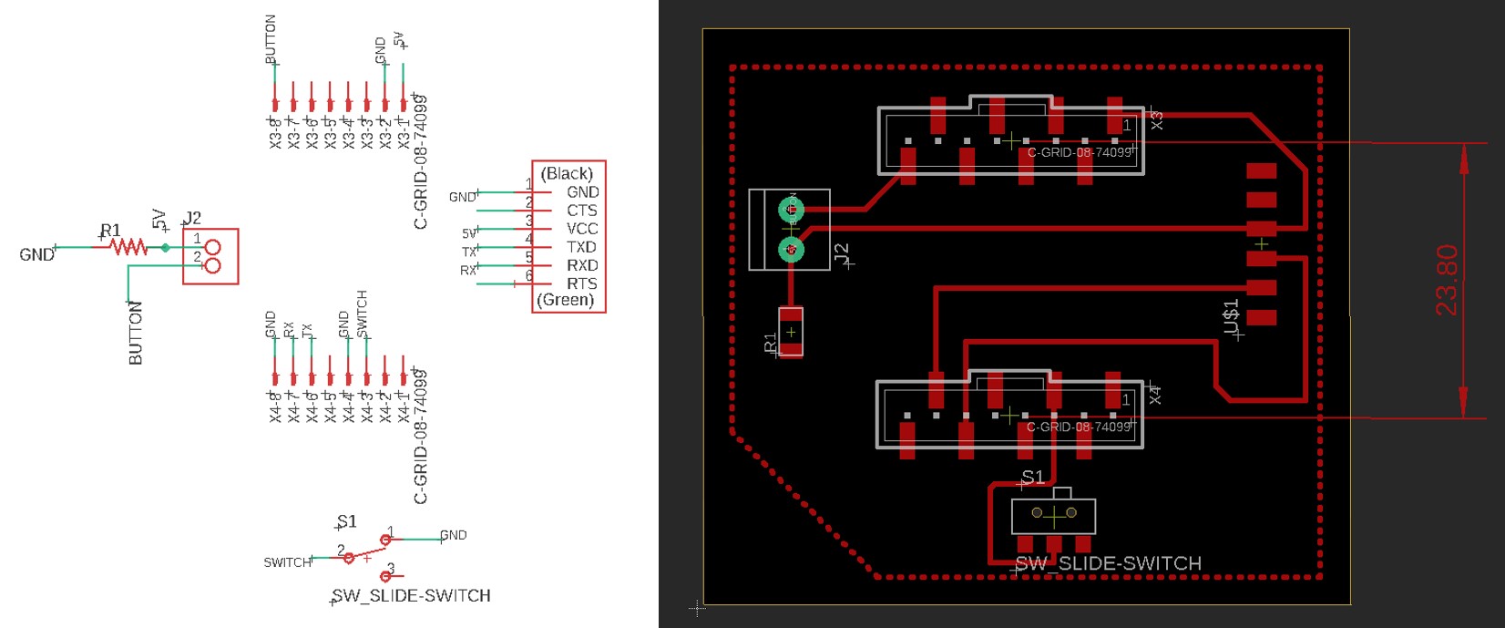
Note:
In designing the board, attention must be payed to the distance between the female headers. These headers are used to directly mount the ESP module on. A distance of23.5 mmto24 mmis ideal. Increasing or deceasing the space too much will lead to difficulties in mounting the module on.
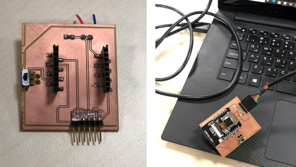
I obtained the toolpath for the milling via flatcam, and milled the board using the Roland milling machine. The steps are the same as mentioned in my electronics production page.
Next is setting up Arduino IDE to use it with the ESP.
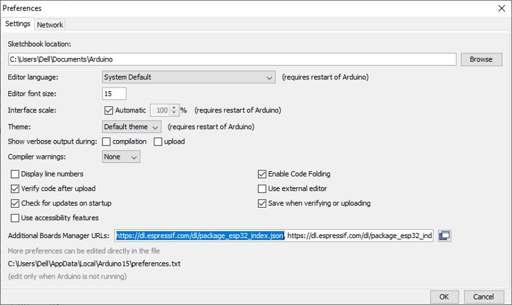
First, I need to install the ESP 32 add on by going to file>preferences, and pasting the following into the Additional board manager URLs:
https://dl.espressif.com/dl/package_esp32_index.json
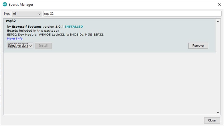
Then I need to select the board I am using by going to tools>board manager and search for ESP32 by Espressif Systems.
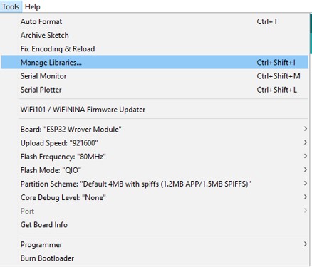
To start using the board, I need to select it by going to the tools > board > ESP 32 Arduino> ESP 32 Wrover. And set the other settings as following:
Next, I’ll test the camera server by going to file > Examples> esp32 > camera> camera web server.
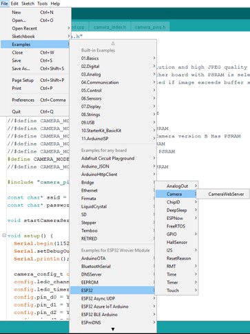
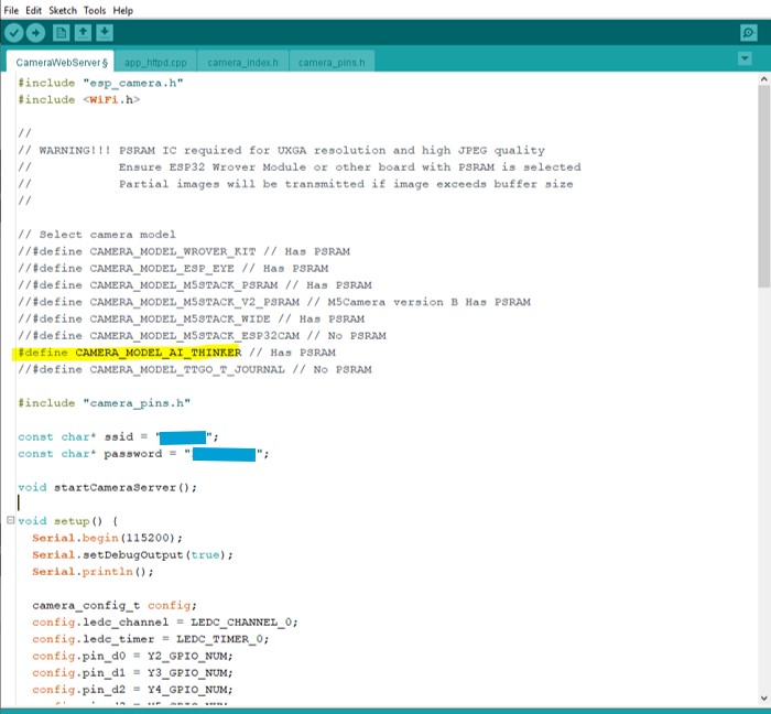
I am using an ESP 32 cam, which is the same as the camera model AI thinker. So I select the model by uncommenting The model I have, and then entering the WIFI credentials.
I mount the ESP 32 cam module on the PCB I made earlier, connect the FTDI cable paying attention to the right connections and select the port from the tools menu. Compile and upload!u
… and that didn’t work.
I got an error stating that I couldn’t connect to the ESP32 board.

To solve this issue, I got help from this page that highlights all the possible errors one can get while working with the Esp and how to troubleshot it effectively.
While reading I quickly notices the very small mistake I made that lead to this error. I forgot to turn the switch!
The switch on the ESP 32 board is a connection between GPIO 0 and ground. To program the ESP, GPIO 0 needs to be connected to the ground, and then disconnected when the upload is done.
So I turned the switch, compile and upload!
… That didn’t work either.
This time I got a different error. Which states that the sketch is too big to compile and upload to the ESP module I have.

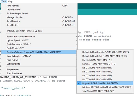
Reading further down the troubleshooting guide, I found out that the solution to my error was by selecting the right partition scheme for the module which is Huge App instead of the one selected previously.
Again, fingers crossed, compile and upload?
This time it uploaded successfully (yes!)
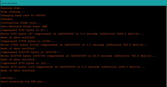
It takes a bit longer to upload to the ESP compared to other board. Once the upload is done, I need to turn the switch disconnecting GPIO 0 from ground, and press the reset button on the back of the ESP module.
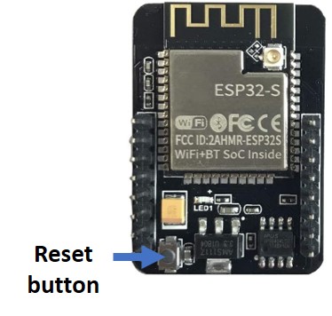
Accessing the serial monitor, I change the baud rate to 115200 and press the reset button on the esp again to check the results. Once the WIFI is connected, the ESP IP address is printed, then I can just copy the address to my web browser and access the local server of the camera.
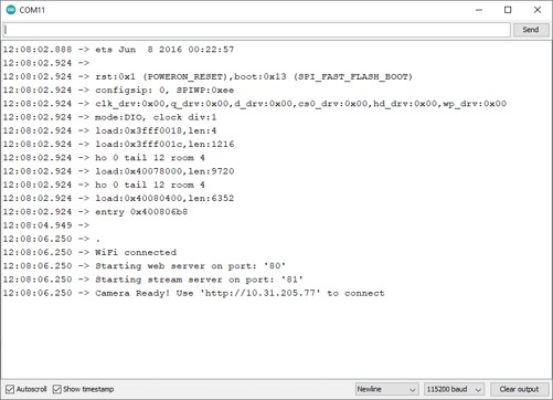
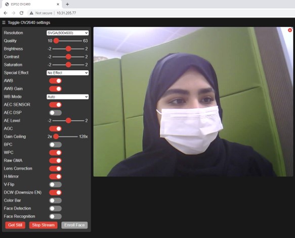
Then, I’ll just change the resolution to SVGA, and start streaming!
The cam server has various options to play with, such as the saturation, the quality, the brightness and the contrast. It even has an option for special effects and filters!
One of the fun options an ESP 32 cam server has is Facial recognition! where the you need to enroll a face, the ESP makes several attempts to save it, and then detects the face once its in the camera parameters. (note: I needed to select a lower resolution for the face detection/recognition feature)
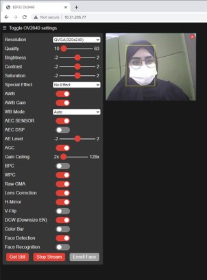
This so far yielded very good results. However, I was wondering if we could alter it further to achieve a better frame rate for the live video.
currently, the maximum frame rate of the video in SVGA is 19.2 fps.
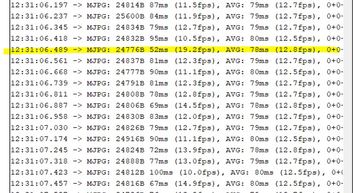
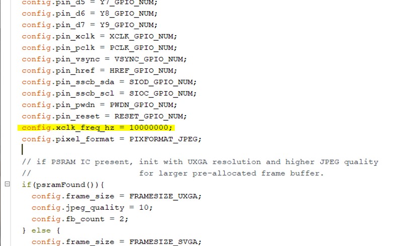
So I searched a t and found this great tutorial to increase the frame rate effectively.
In the Esp camera sketch, I changed the clock speed from 20MHz to 10MHz, and the maximum frame rate I got in VGA is 29 fps, while it reached 76 fps in QVGA!
The other input to my final project is a button that is connected to the flash GPIO pin of the ESP module. The button is connected to a 10k ohm pull down resistor, and it turns on the flash on the module when its pressed. For the final project the button is required to take snapshots of the objects and upload it later to the server.
button working with the flash: (note: beware of the flash in the Esp module, its quite strong and I almost went blind with constant trials)
Please find the full group page here.
For the input devices week, I am measuring the signal of one of the button in my ESP 32 board.
The button is connected to pin GPIO 4/ flash. When this button is pressed, the flash on the ESP 32 board is turned on, and the camera captures an image as explained in my Final project page.
I am using the oscilloscope to measure first the input voltage I am supplying to the board (measured to be 5 volts), and then the signal of the button as it is pressed.
