
This week had been a busy week full of trials and errors and many lessons to learn. Moral of this week:
“Repetition is the mother of skill”
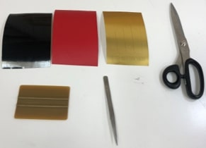
Computer Controlled Cutting was the topic of the third week in Fab Academy. In this week we tried different laser cutting machines along with vinyl cutting machines. Our goals were the following:
cut something on the vinylcutter
Document everything!
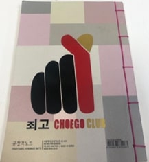
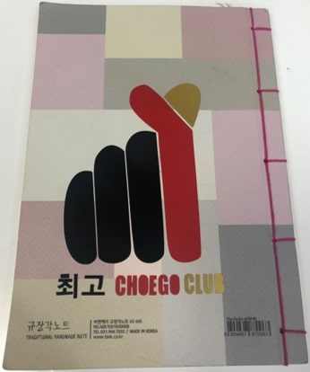
For this task, I decided to print the logo of my beloved community, the student club that I personally lead for a couple of years, the place where ideas became realities, and people from different backgrounds came together to share one passion.
[All credits for logo goes to Azizah Ahmed Al sharif , our wonderful graphic designer]
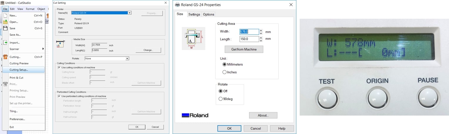
The vinyl cutting machine available was the Roland CAMM-1 GS-24, and the software used was CorelDraw 2017.
The following process was kindly instructed by Waleed Al Hamdi and Hashim Al Sakkaf
I started the process by directly copying my picture to the workspace on a new project file in CorelDraw. Upon selecting my picture, I right clicked and chose Quick trace. This is to create a vector copy of the image so the machine can print it.
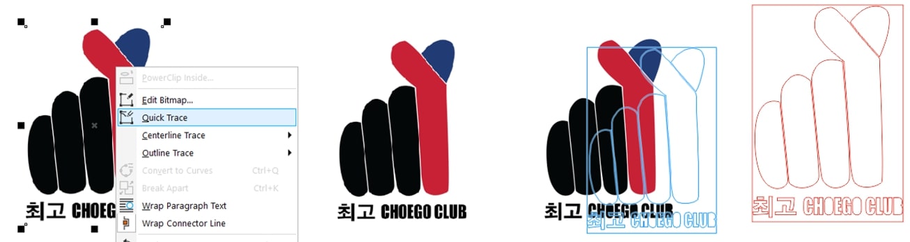
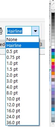
Now, since the original logo had 3 colors, I decided to get creative and do my logo with three colors as well. I selected the picture and chose hairline as the ideal thickness, and right clicked the red, blue and black on different parts of my logo using the color bar on the left.
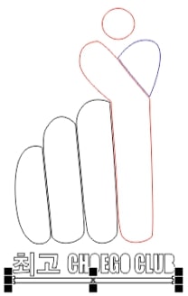
Proceeding, I ungrouped the image and added some markups so it will be easier to guide pieces of the logo to where they belong and grouped the object back.
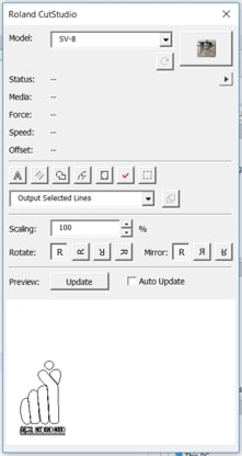
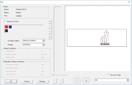
Next, Without clicking on the picture, I clicked on the Roland Cut studio icon on the upper tool bar. This is a tool that connects CorelDraw directly to the software activating the Roland Vinyl machine.
When the window pops out, I went back and selected my image and clicked on update so my design is displayed in the preview space on the bottom and then selected output selected lines to cut only what I have selected and clicked on the Roland logo to proceed to the next step.
The “next step” is the Cut studio software, which opens a window displaying the design. I went ahead and clicked on file >> cutting setup >> media size >> change , changed the width according to the value displayed on the machine, and changed the length to a much more manageable value.
Lets stop with the software here to check the machine before we proceed to the final cutting command.
Adjust the start point of the sheet by first pushing the handle on the left to release the motors grip and then I can adjust the sheet easily, and pull the handle back when done.
Adjust the motors if the grip is not perfect on the sheet.
Adjust the Force if needed.
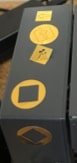
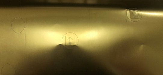
Test the cutting setup by pressing and holding the TEST button for a couple of seconds (the test will print a nice circle with the letter T inside)
The final step on the software is to click on the cutting icon on the upper toolbar and click on OK.
I repeated these previous steps for each roll, each time taking the time to allow the machine to automatically measure the width of the roll and enter the value back on the software.
I ended up with black and red sticker sheets (obviously) but we lacked a blue roll in the lab, so what’s better than Gold to brighten up the day!
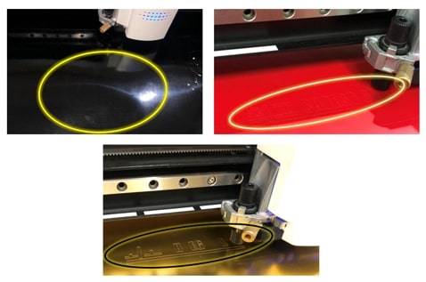
The sticker outlines are quite hard to see on the red and black sheets while printing, so good luck squinting hard!
Immediately upon finishing the cutting, I trimmed the pieces from the roll, grabbed some scotch tape and prepared my station for the tricky part.
I started by carefully removing the tape around my design, I referred to my design picture to see what to remove and what to keep based on the colors of the parts. Next, I adhered some scotch tape to the design, and made sure that there are no air bubbles.
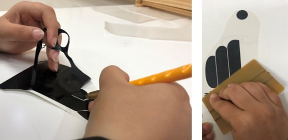
The red and black sheets peeled and adhered perfectly to the tape, however the gold sheet was a mess! The sticker refused to peel, so I went back to the vinyl cutting machine to try printing it again. Luckily for me Waleed was there to help.
Apparently, the Gold sticker sheet proved to be made of a thicker material compared to the red and black sheets, so we tried testing different forces. We tried the default 40% up to the perfect force value 150 %.
After printing the design again on the gold sheet, I went back and repeated the same procedure of peeling and adhering.
Next, I adhered my design, a color at a time to my language learning notebook. I started with the black, again making sure to eliminate any air bubbles in the way. Then the red, making sure to place the guides I made directly on top of each other, then finally the gold.
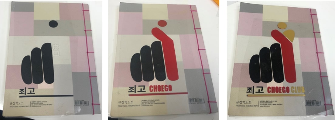
The final product looked like this!
Albeit a second look, there was a problem with the sticker. The ㅊ in the first word was turned into a ㅈ! This changes the pronunciation of the word from choego to joego. Nothing a good piece of black sticker could not fix!
There!
Another thing we have tried was the heat press machine. For this, I have used the same logo but without the text below.
I performed the steps above to cut using the vinyl cutter and peel off the extra sticker.
In this part we used TheMagicTouch heat press machine to transfer our designs to the T-Shirts.
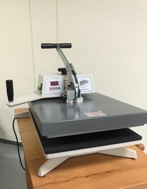
The T-shirt is placed on the plate of the machine, then the design with the sticker side down is placed. The handle is then pulled down to press a plate heated to 160 degrees to the shirt for about 10 seconds. Then the transfer layer is carefully removed revealing the design!
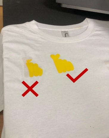
As noticed, I have tried the press heat twice. The first time it didn’t work because the plate wasn’t heated enough, and I didn’t wait enough for the sticker to cool down on the clothes. The second time I made sure that the plate was heated, waited longer while pressing the plate, and waited for the sticker to cool down.
For the group tasks we each were assigned different materials with different thicknesses to test on the three Laser cutting machines available in the lab. Our work as a group can be found on this page.
In this task, I wondered a lot about what I should be creating! The options were endless and the time was sparse.
My initial idea was to create what I assumed would eventually look like binoculars. I fast-sketched disfigured lenses and body on my notebook, began my work on fusion 360. And ended up with something that looked like this:
I don’t think I quite understood the dimensions I was working with, but I went with the flow and decided to cut it out using the universal laser machine.
The first attempt was cut in the same dimensions of the original sketch in Fusion, which proved to be too big .. and has wrong scales of the slots.
These are some of the notes I took when tried the first prototype:
My second attempt of creating the binoculars were set to fail as well, that is because - and I realized this later - I used to change the dimensions in the laser cutting software instead of fusion, which scaled the heights, and slot widths according to how big or small I make my design. This is what my second attempt looked like:
And the notes I took:
Eventually, I gave up on the binoculars due to the lack of time, and I decided to make something simpler, and that would consume less time to design.
So, I switched to a plane instead!
I started out again by looking at different pictures on the internet to get some inspirations of how a plane would look like.
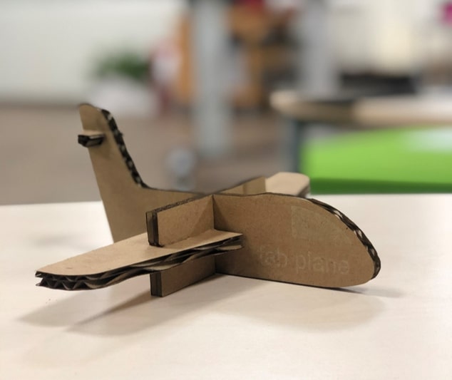
Then I sketched a quick drawing and proceeded to work it out on fusion 360. I took my time creating the main body, the wings, the holding middle piece and the tail wing.
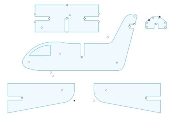
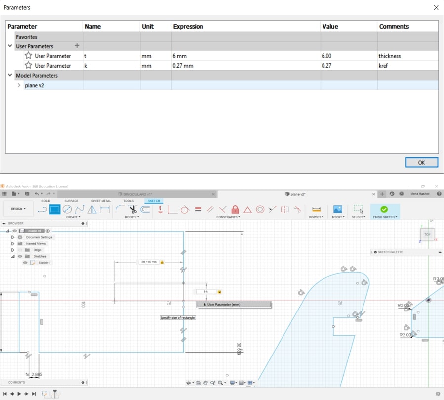
Although we were asked to create out design using parametric parameters, I couldn’t apply the concept to the whole design, as the body of the plane, the wings and other parts had too many curves, fillets and lengths to take into considerations.
Instead, I made sure that the thickness (slot width) and the kerf values were used parametrically to ease the modification of the design.
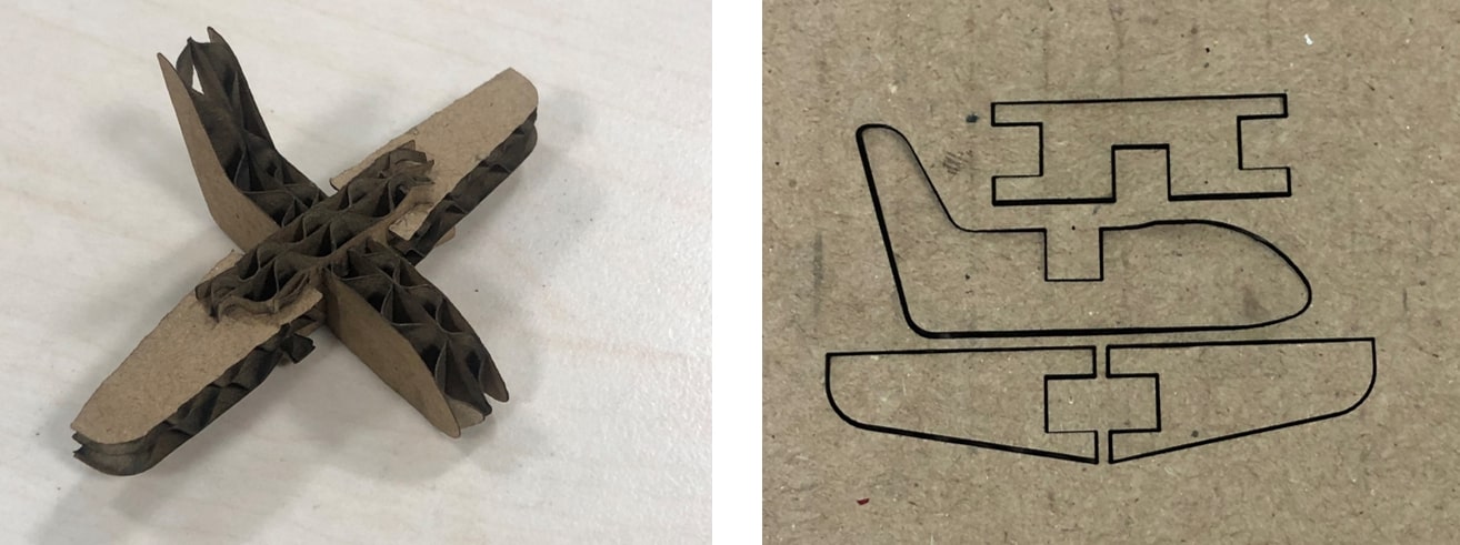
For the first time I laser cut the plane, I have made it intentionally small, to save space, and document any errors in the dimensions of the sketch.
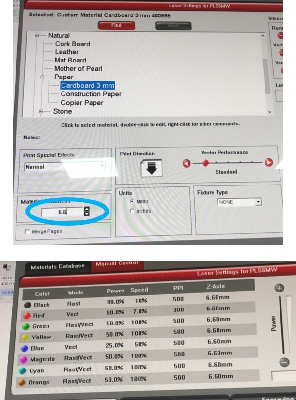
I have printed my planes using the same universal cutting machine I used previously in the group assignment, this time however, I ignored the error message regarding the thickness and inputted the value as it was 6.6 mm, along with the power being 80% with a speed of 7% and a frequency of 300 ppi as this settings worked best with the thickness provided.
The prototype came out good, the slots were fixed nicely and it was time to upscale this plane!
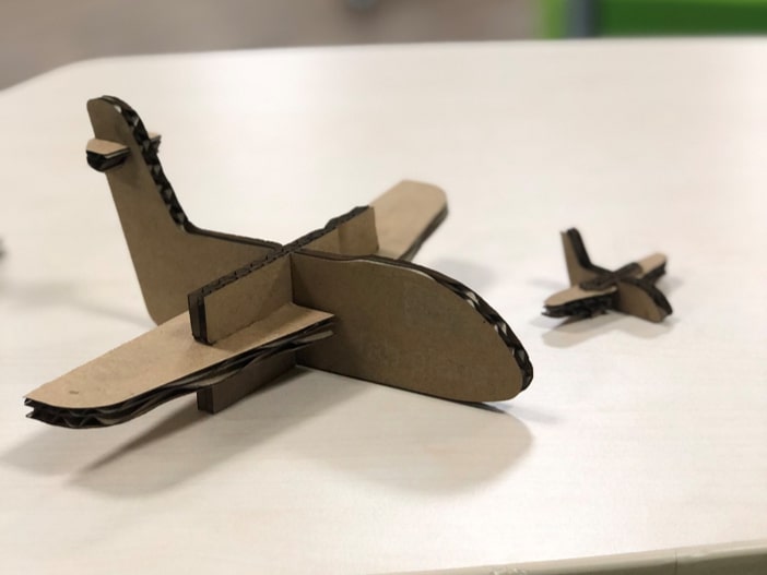
I scaled the sketch in fusion and made it bigger and tried laser cutting it again.
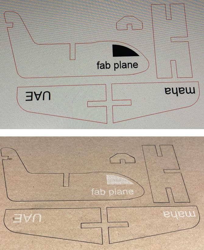
Here’s a comparison of how the two planes looked like along side each other.
As I was browsing the internet for other inspirations and ideas, I came across Shirley Huang’s work on her second week. She had made an a non rectangular box using origami! So I thought I should try create my own since it looked so cool!
I browsed the internet (again! the internet is the most powerful tool!) for designs to make, and came across different “twisted polygon prisms” on Pinterest. So I decided to create one.
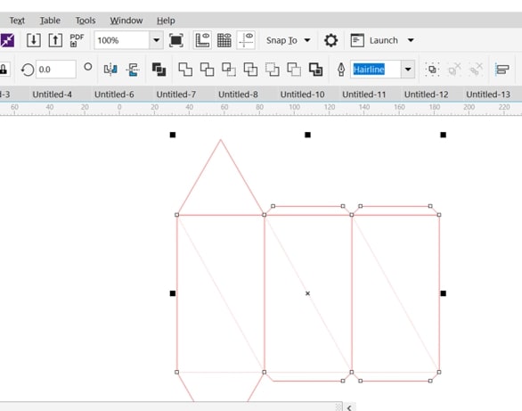
To start off, I used fusion 360 to create a three rectangles, two triangles and some edges for my twisted triangle prism. I have also added a diagonal line across each rectangle which would later be the bending line that I’ll use to twist the prism.
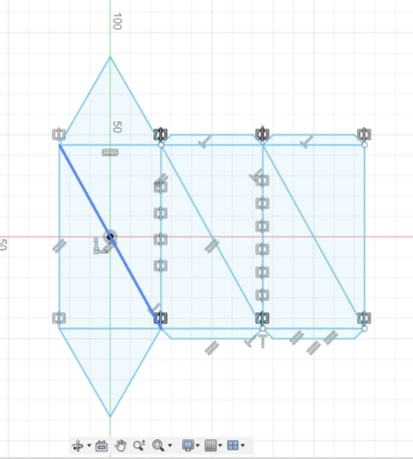
To distinguish between the bending lines and the cutting lines, I have marked the bending lines with the construction tool option in the sketch palette. This forms a dashed line in a different color than the rest of the design.
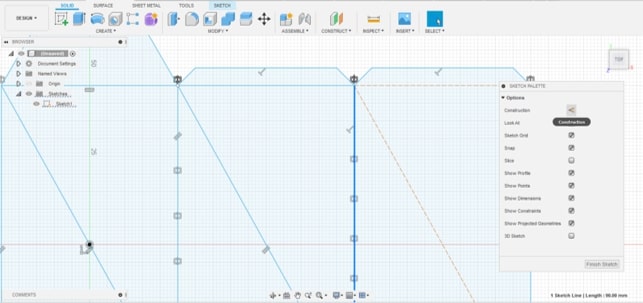
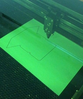
My initial aim was to cut the design using the vinyl cutter, but hence our instructor Hashim told us that the laser machine can also be used to cut paper, I decided to give it a go! (silently praying that I wont burn the place down).
For this task I used the Universal laser machine, where I opened my file in CorelDraw. Unfortunately, The construction lines I have created in fusion did not appear as dashed anymore, so I had to manually change the line type in CorelDraw.
For my first trial, I chose Construction paper as my material, and for the settings I decided to test the default settings which were:
| power | speed | Frequency |
|---|---|---|
| 100% | 0.03% | 500 PPI |
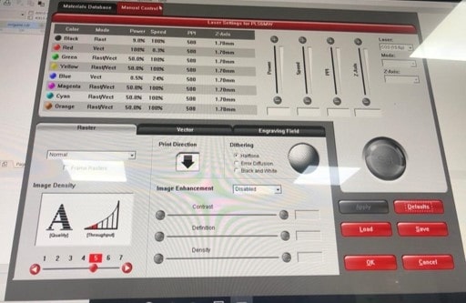
Needless to say that the paper caught on fire! The power was too high for the material, and the speed was too slow!
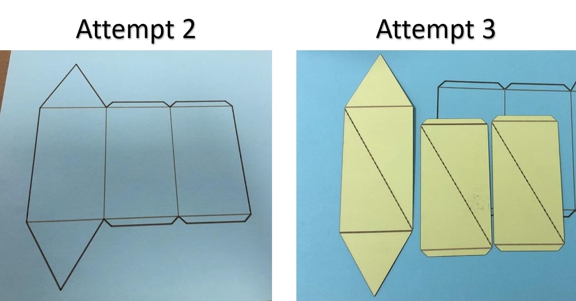
My next attempts went as following:
| Attempt | Power | Speed | Frequency | Notes |
|---|---|---|---|---|
| 2 | 50% | 10% | 300 PPI | The paper was not cut properly, the laser beam did not reach the back of the paper thus the design could not be removed. |
| 3 | 65% | 10% | 300 PPI | The outlines of the design and the bending lines of the triangles were cut properly, however, the laser has cut the whole outlines of the rectangles leaving the pieces apart (fail!) |
| 4 | 60% | 12% | 300 PPI | I increased the speed hence the cut was too slow. The outlines were cut perfectly, and so were the bending lines. (it’s a success!) |
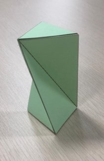
The next part was building the prism, I pre-folded the bending lines and constructed the prism, gluing the edges so the prism sides stay attached. Then Twisted the prism along the diagonal lines. The result prism looked like this! Pretty cool!
As mentioned before, My first and second attempts at constructing a parametric design were not met with giant success. But I still try again, because …. read the second line in my documentation :)
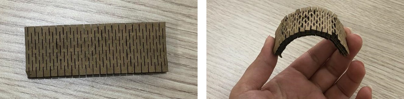
One of the things we were introduced to this week was designing a kerf that would allow the bending of a solid material such as wood or cardboard. Our instructor Hashim recommended us several designs that we can experiment on with the help of the Trotec guide.
The shape I attempted was the straight cut lines.
I had tried experimenting with the size of the slots and the distances between them to decipher the perfect ratio for the design.
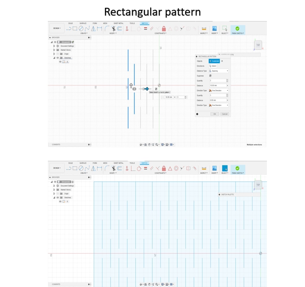
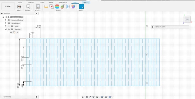
My first attempt was simple and it worked quite fine. I created a rectangle, and drew several lines, then I used the rectangular pattern tool to create copies of the design along the big rectangle and I used the laser machine to produce the piece. (I used the same settings mentioned earlier for cardboard).
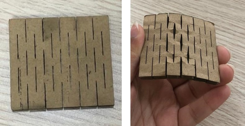
The piece was large so it didn’t give the best curve when bent, but over all it worked.
By the second attempt, I was trying to figure out how is the height of the slots is related to the size of the design itself, and how is it relevant to the vertical and horizontal distances between the slots.
So after several trials and errors, here are my deductions for the perfect ratio (that worked for me!)
I tried two different patterns:
PATTERN 1
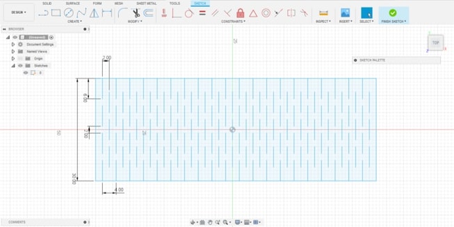
For this pattern, I used the following settings:
And the result was a good flexible piece of cardboard.
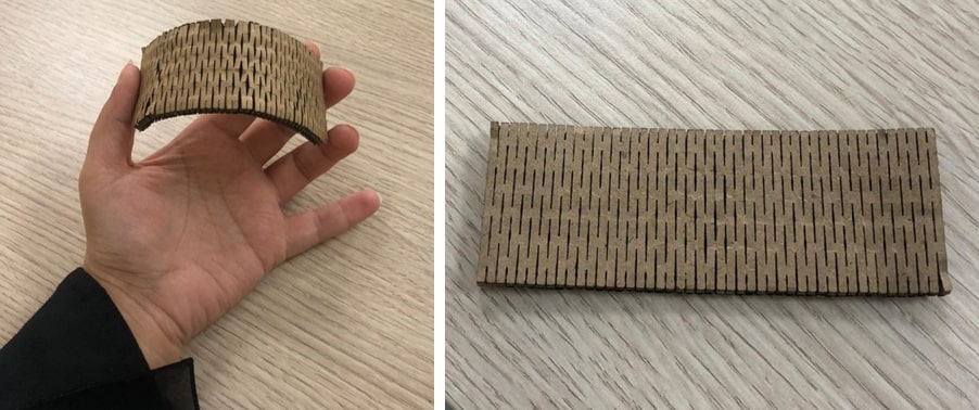
PATTERN 2
For the second pattern I used these settings:
Again, this is a good flexible design for the cardboard that I prefer to the first pattern hence it the bending curve achieved in this case is better.
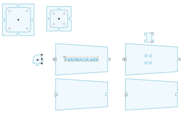
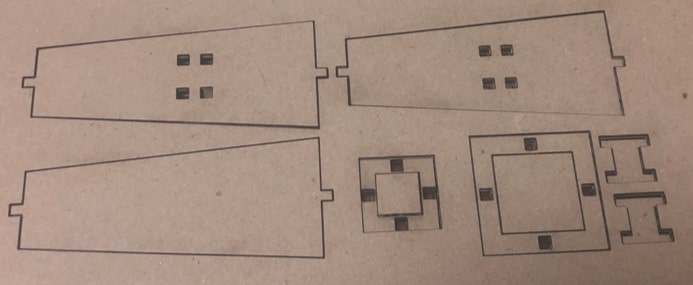
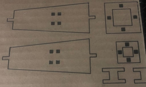
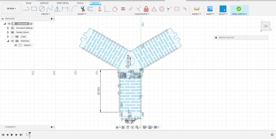
Next I created my pieces for the parametric design. I chose pieces that were simple and easy to build hence the design had to be adjustable and can be tailored to one’s desire.
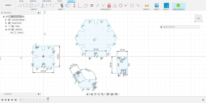 I used the same cutting parameters mentioned previously to cut the design.
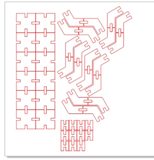
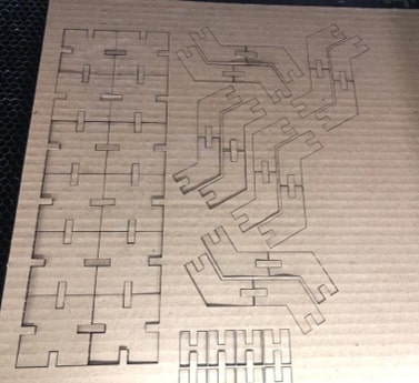
I have also added a bending kerf to my design.
Then I summoned my non-existent inner artist to construct the design and this is what I came up with. A lovely basket!
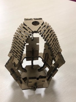
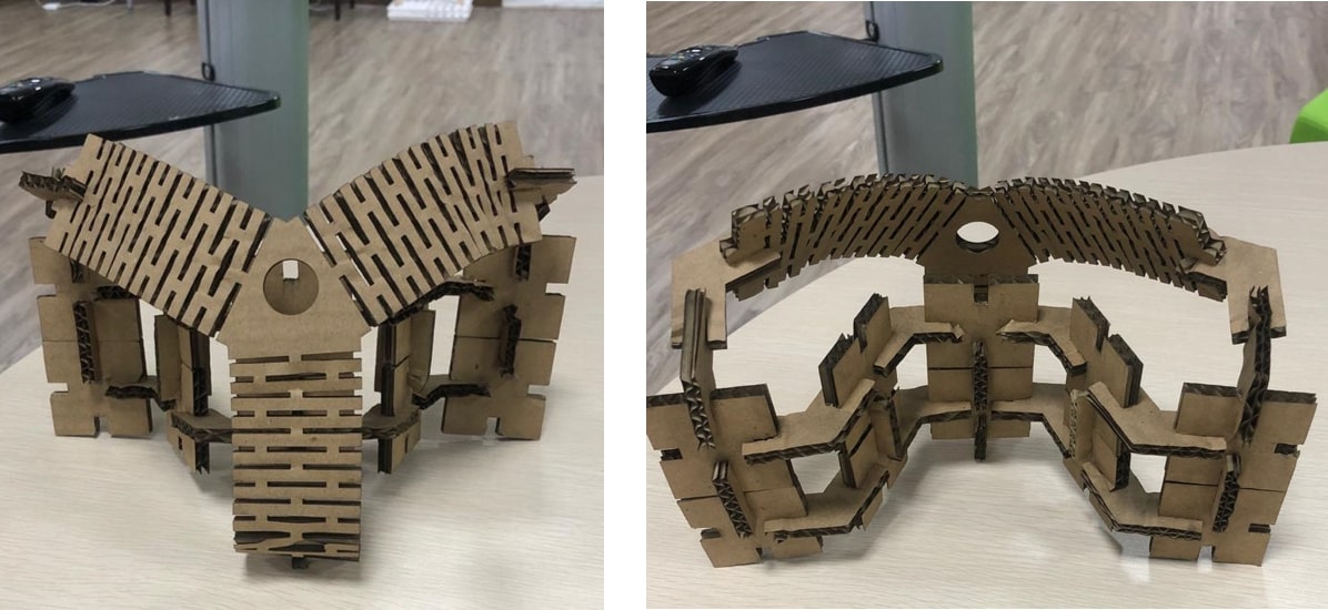
And since the design was supposed to have the ability to be constructed in more than one way, I tried another design! and it’s something .. weird binoculars? a revolutionary design for a future steering wheel? Terminator?
Design files:
