Quentorres. swd+uart adapter+hello board - xiao rp2040
The perfect combination of a programmer to rule them all and a hello board to learn to program. The original programmer created by Quentin Bolsée and redesigned by Adrián Torres. Quentorres is born at the 2024 Instructors Bootcamp held in León. Many thanks to Miriam Choi for the logo.😍
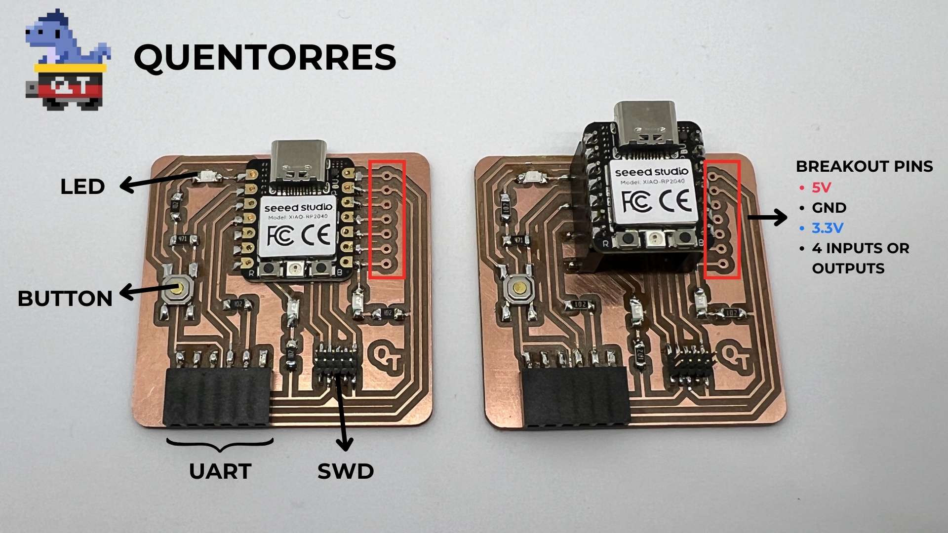
This board can program the new AVR Series 1 and 2 for example Adrianino and the ARMs for example SAMDino. It also has a button and an LED to learn to program in C, Rust, Go, Micropython... It has breakout pins in case you want to connect other external elements.
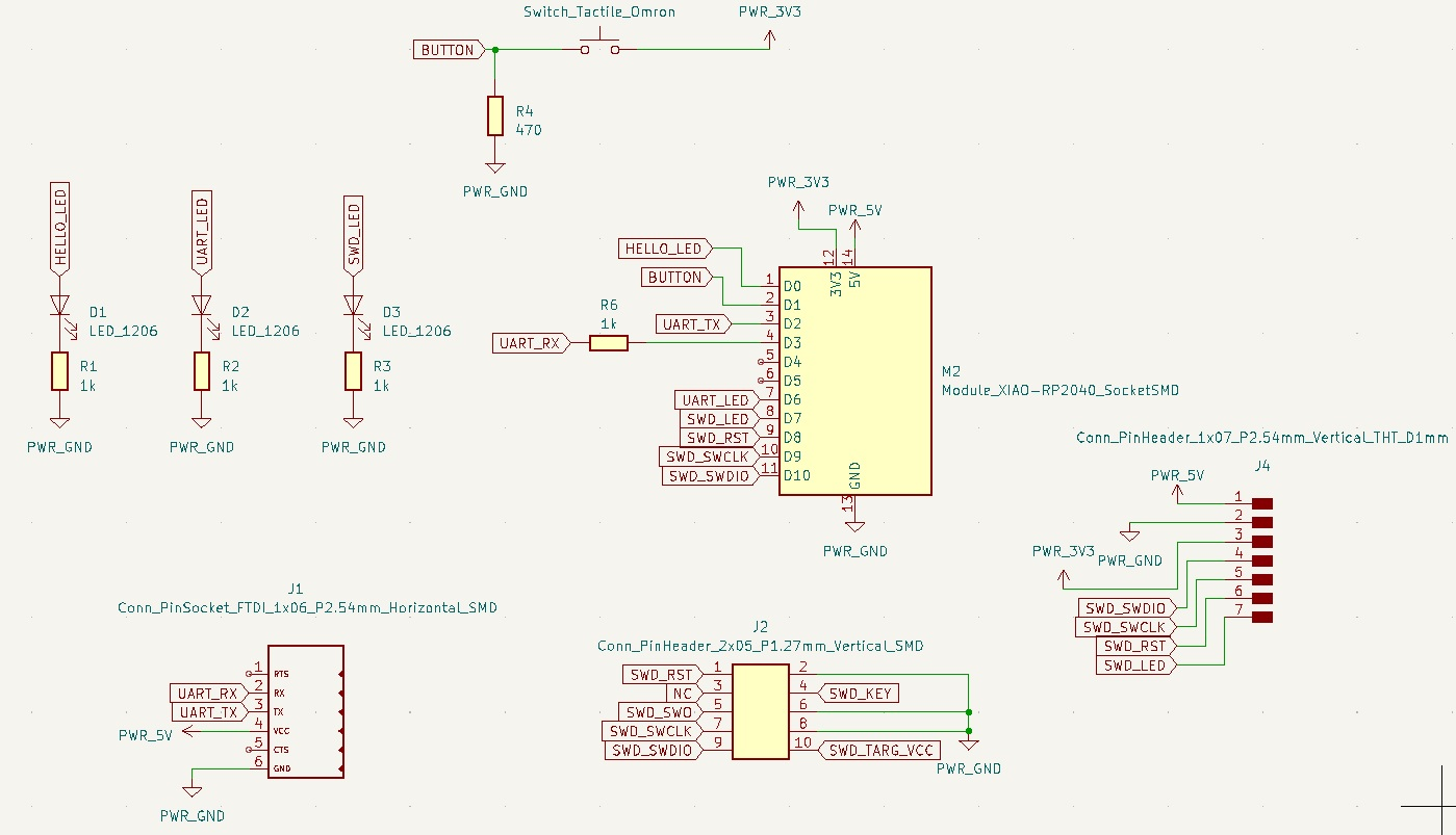
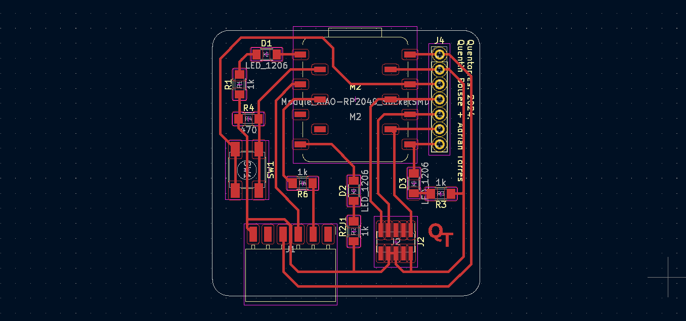
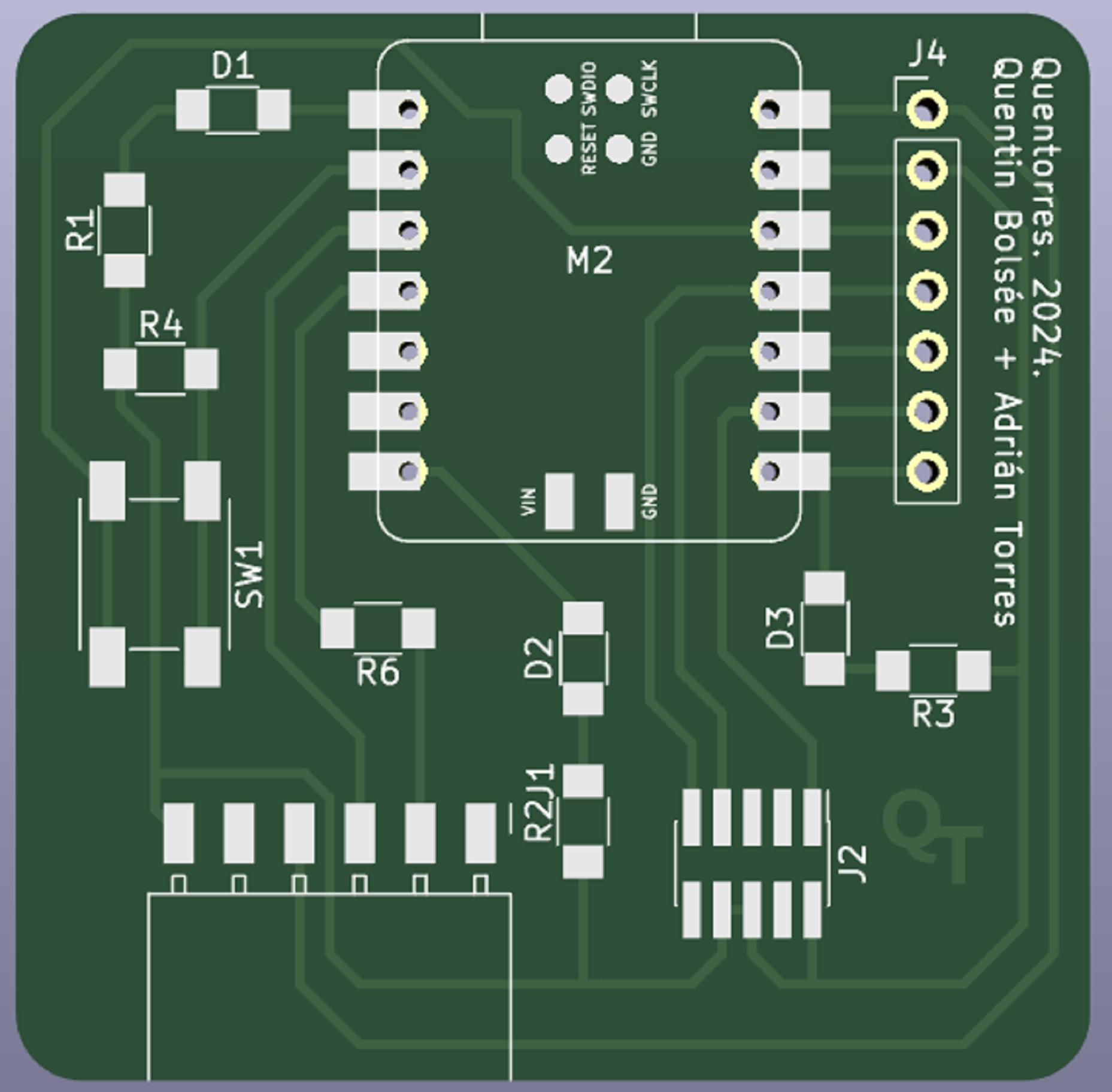
Schematic
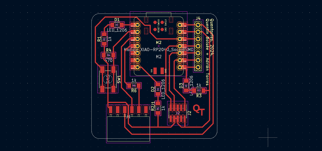
Board
There are two versions:
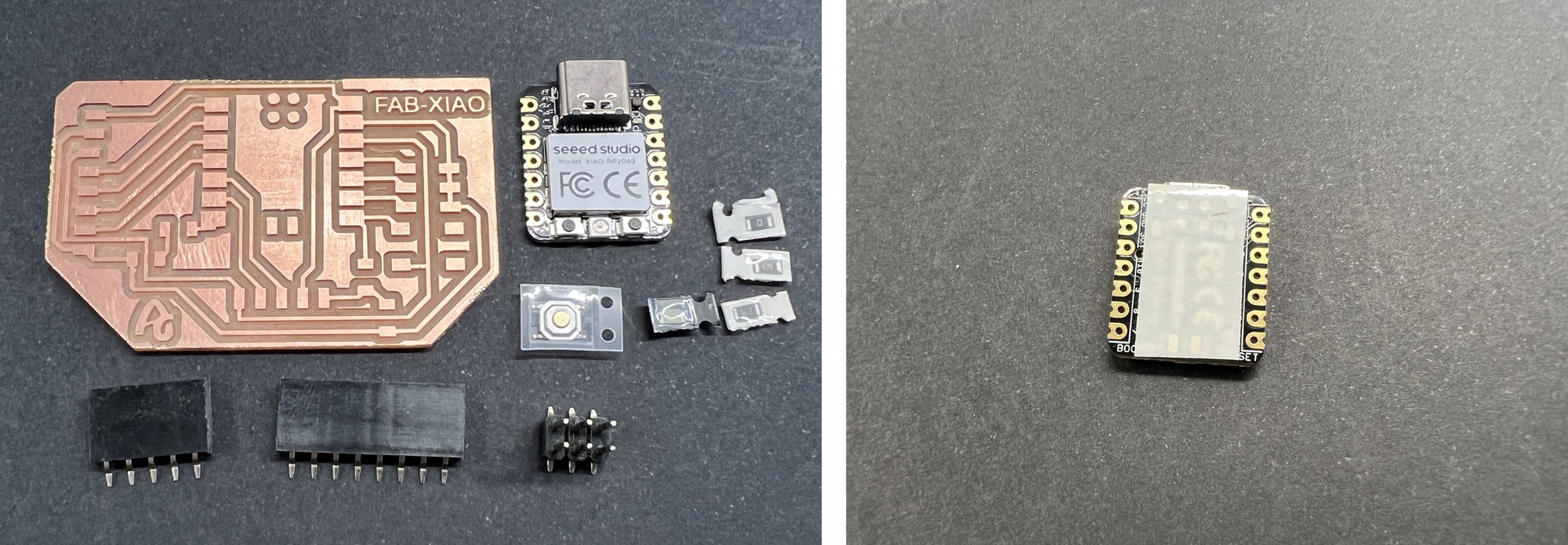
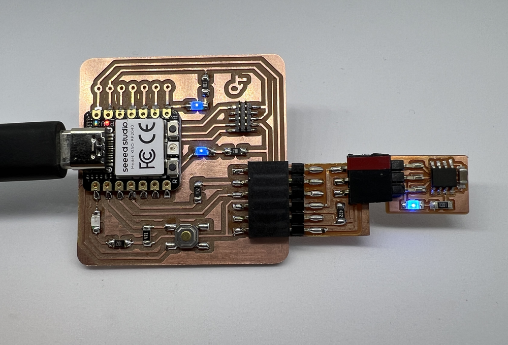
 The XIAO RP2040 can be soldered directly to the board. I recommend protecting the bottom with 3M™ Epoxy Film Electrical Tape 1 like in this image.
 The XIAO RP2040 can be removed using the following connectors.
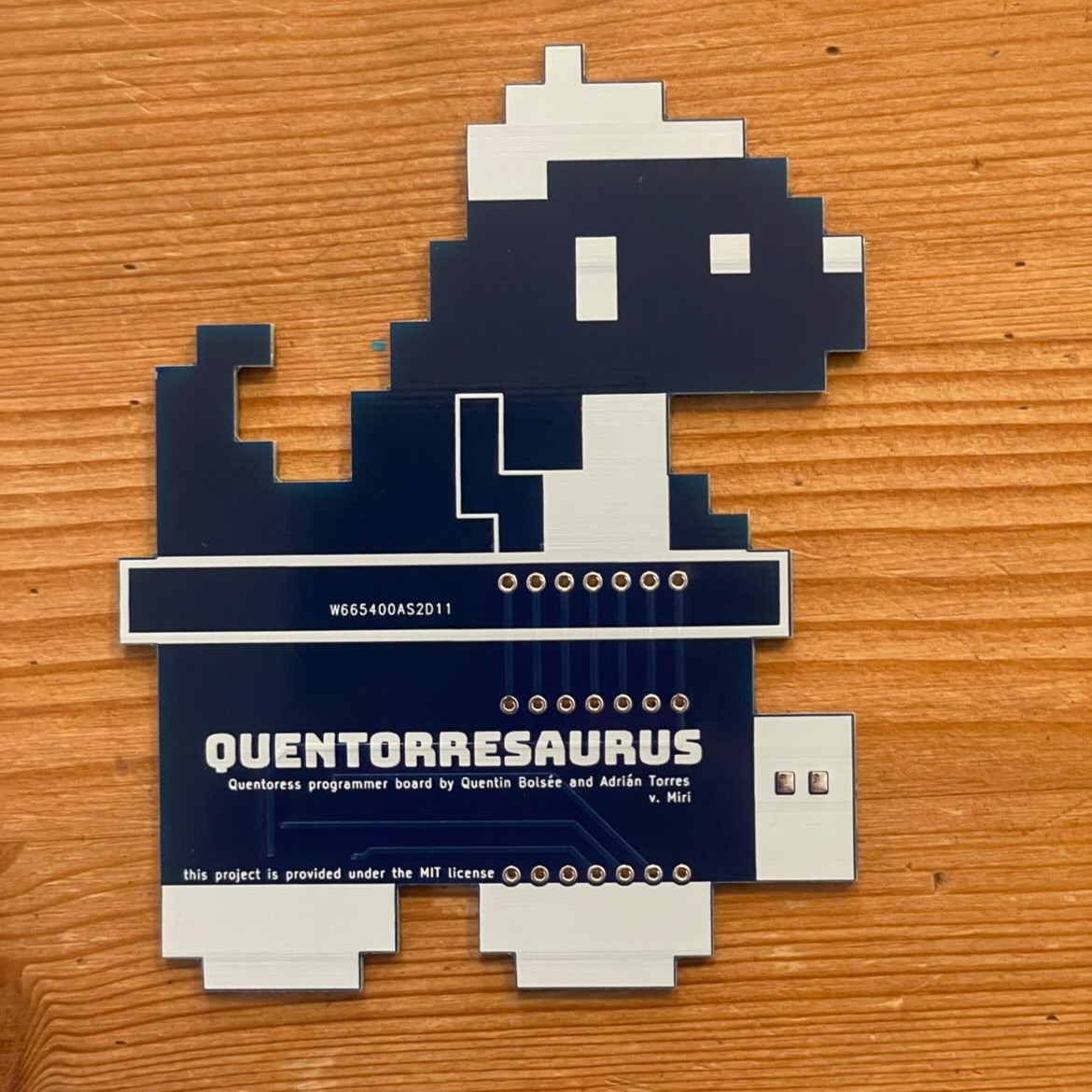
Quentorresaurus:
Miriam Choi redesigned the board and created a fun Quentorresaurus. Here you can find the files to create yours.
Components
*They are only necessary if the XIAO is not going to be soldered directly to the board.
How to use as a hello board
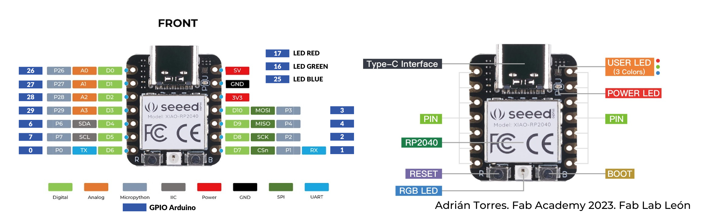
The board has an integrated LED and a button. With them you can learn to program. The LED is integrated on GPIO Pin 26 and the button is on GPIO Pin 27.
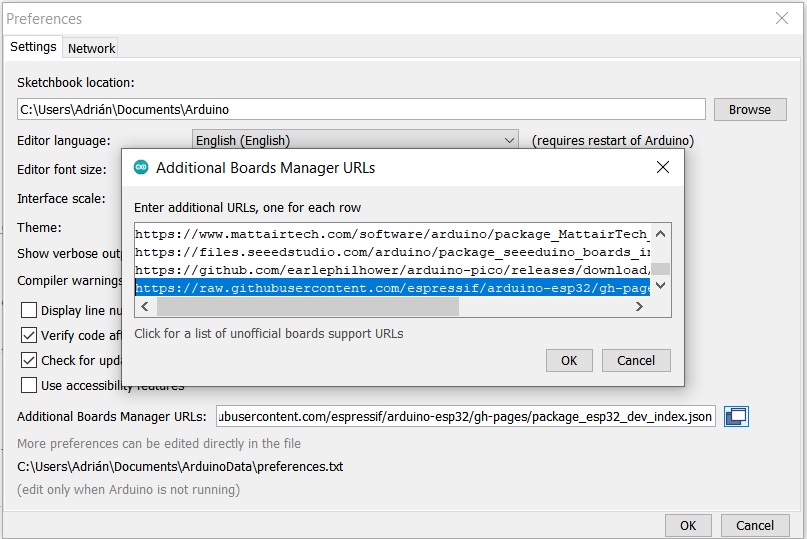
Step 1: open the Arduino Program
In File->Preferences, we will add the URL of the additional boards that you can find here. We need the Arduino-Pico by Earlephilhower.
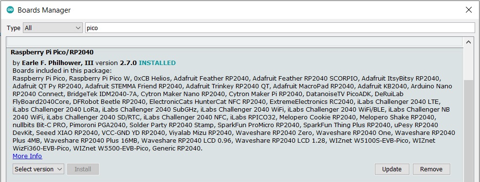
Step 2: boards manager
The next step is to download Pico in the boards manager. Tools->Board->Board manager
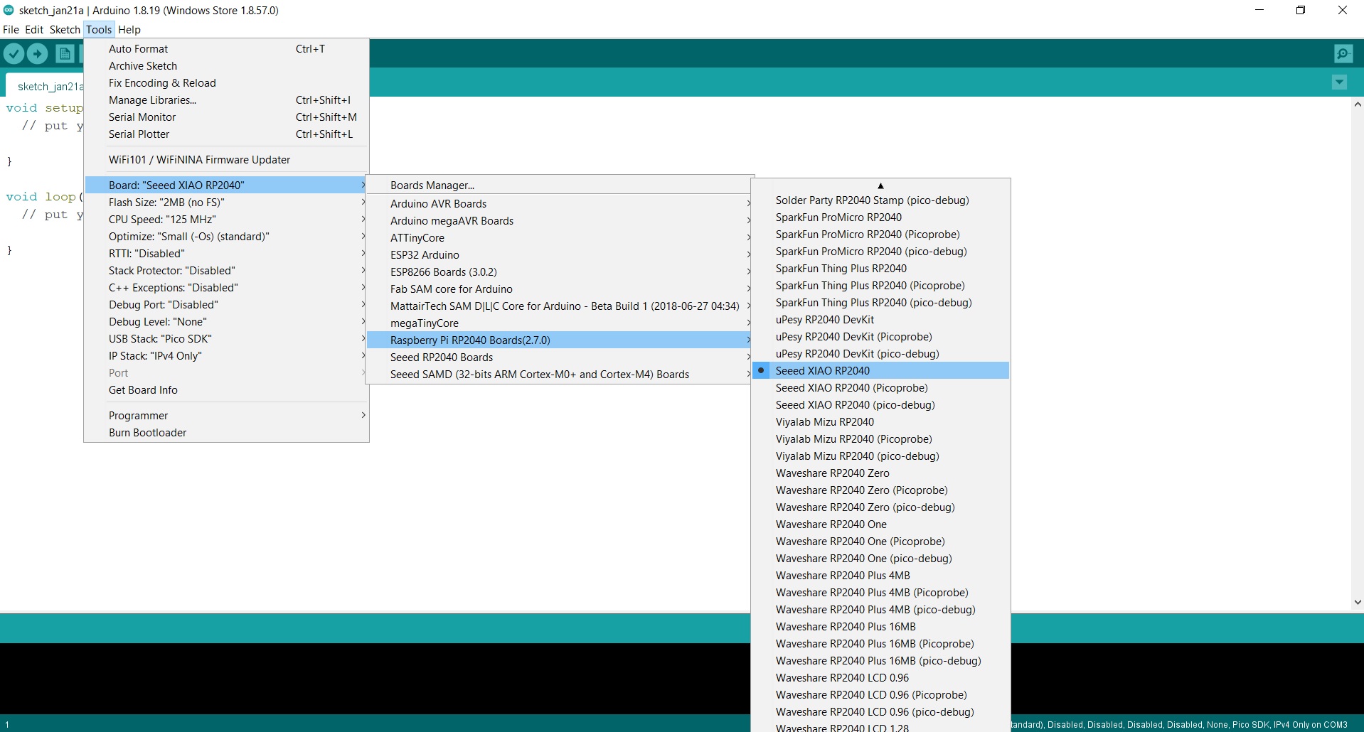
Step 3: configure the Arduino IDE for the Seeed Studio XIAO RP2040.
We configure the Arduino IDE for the Seeed Studio XIAO RP2040. The Seeed Studio XIAO RP2040 will appear in the COM port, in my case in COM 3.
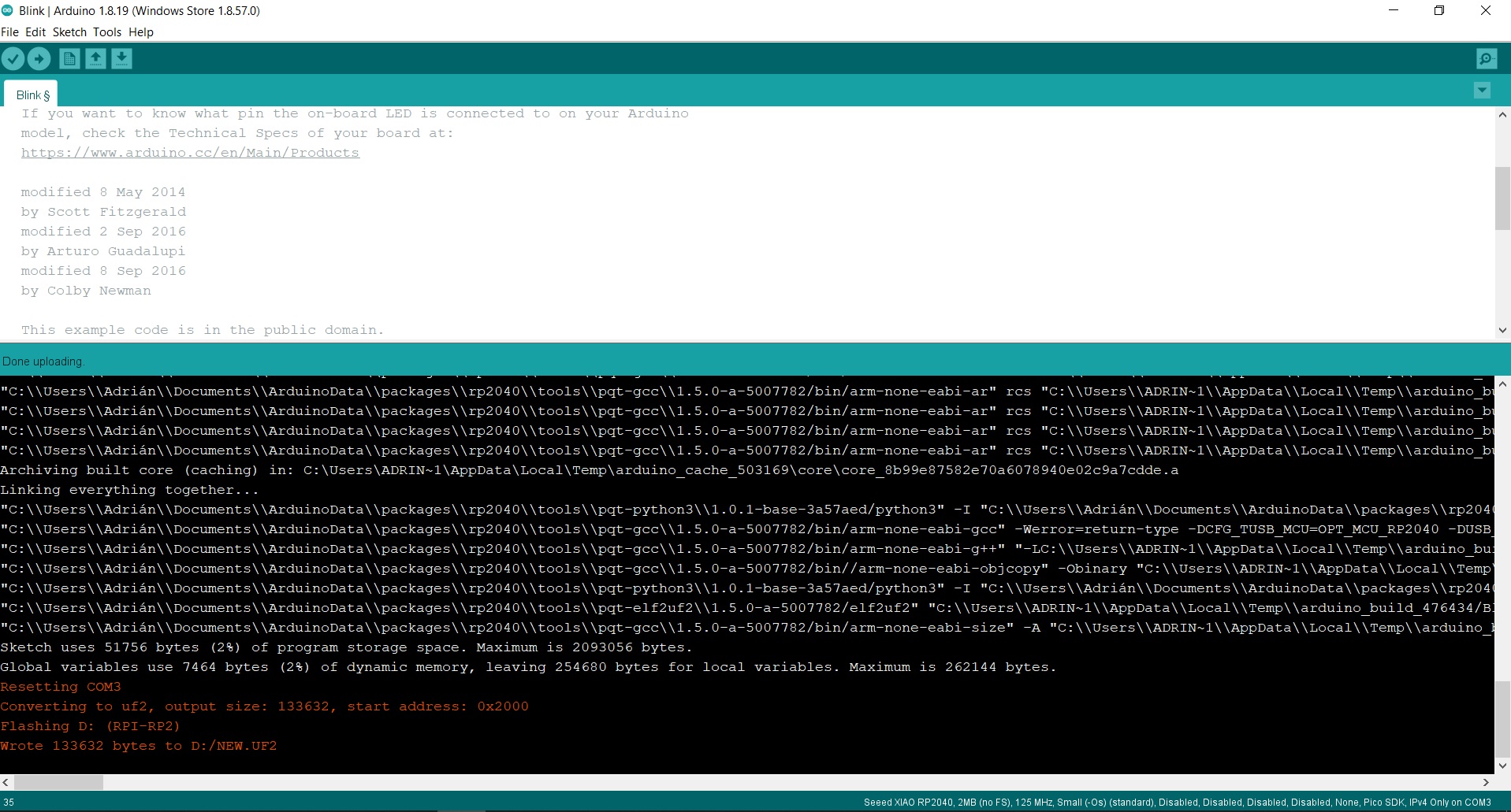
Step 4: load the Blink program.
Now load the Blink program so that the LED on pin 26 (GPIO 26) blinks. When we upload it, all this information appears in the notifications section.
In this short video you can see the operation of a Blink on pin GPIO 26 (26 in Arduino) where the LED is integrated. 😍
How to use as a programmer
Install firmware
To flash the board and make it ready for use as a programmer, the easiest is to install the uf2 file available here.
IMPORTANT: If you use a MAC I recommend that you use a USB C (XIAO) to USB 2.0 (MAC) cable or a converter. The protocols of the new MACs are very restrictive to flash the XIAO. (Thank you Nuria for the report).
Step 1: press "boot" and "reset" simultaneously
Connect your board to a computer via a USB cable. Press the button labeled "B", then hold it pressed while pressing the button labeled "R". You can then release both buttons, and the rp2040 will enter its reset mode. It that mode, it exposes its flash memory as a hard drive.
Step 2: place uf2 file on the hard drive
Download the uf2 firmware file from here, and place it on the empty hard drive that showed up after step 1. After the file transfer, the board will automatically reset.
Step 3: the board is ready to use
To verify that the board is functional, you can check that it correctly shows up as a connected USB device. This device should advertise two USB endpoints: a serial port, and a swd programmer.
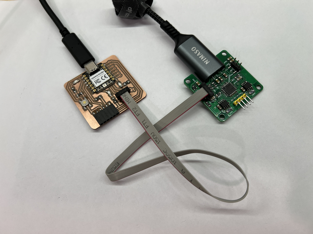
Flashing a SWD target
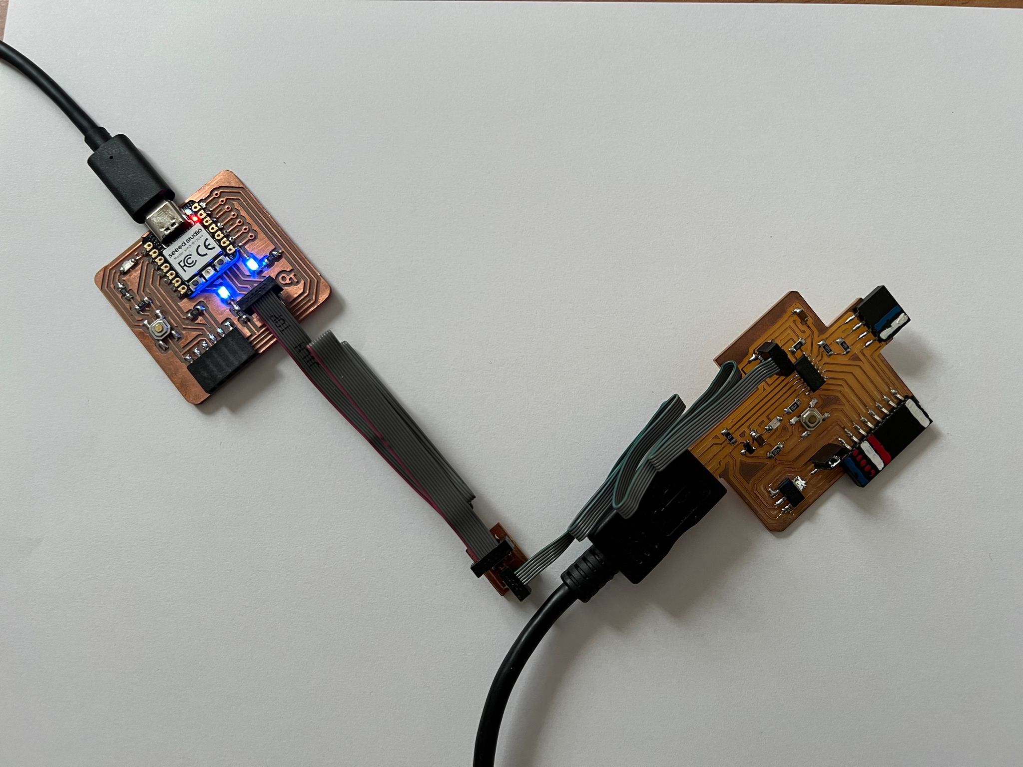
To program a SWD target, simply use the 2x5 pins JTAG connector, keeping in mind the correct orientation of the connector. On the programmer, the ground pins are located on the side closer to the edge of the board.
You can also program the SAMDino using the hello.SWD.10-4 converter.
Make sure the target is powered and the programmer is correctly connected to your host computer. You can then flash your target using edbg, for instance:
edbg -ebpv -t samd11 -f sam_ba_SAMD11C14A.bin
If successful, the output should be:
Debugger: Alex Taradov Generic CMSIS-DAP Adapter D13C3C81 2.0.0 (SJ)
Clock frequency: 16.0 MHz
Target: SAM D11C14A (Rev B)
Erasing...  done.
Programming................... done.
Verification................... done.
Alternatively, if you're using the Arduino IDE with the Fab SAM core installed, you can use the embedded edbg. To flash the bootloader on the target, click on Burn Bootloader:
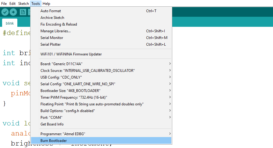
Your flashed target should then show up as a serial port.
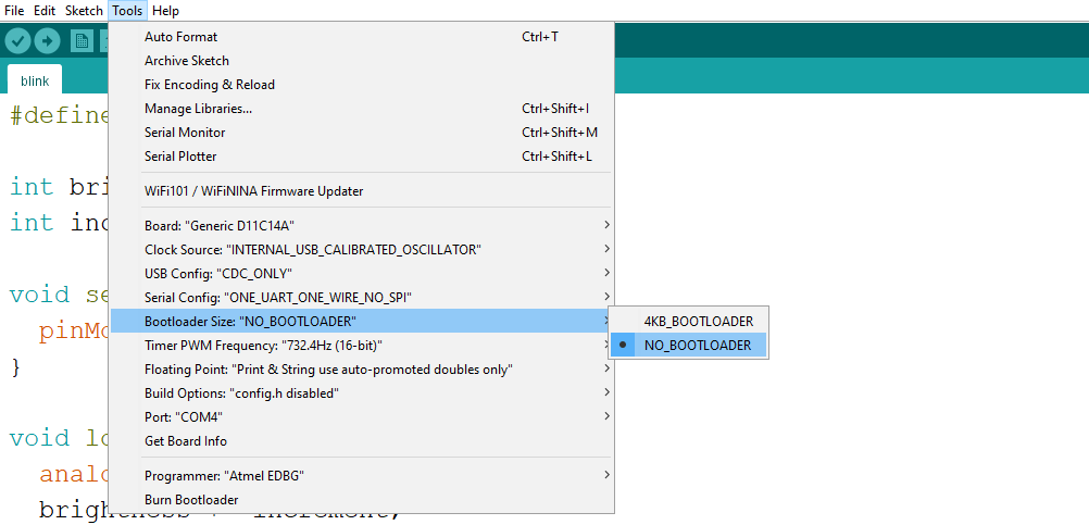
Alternatively, you can skip using a bootloader altogether to save some flash. Simply select NO_BOOTLOADER and upload; the IDE will automatically use the programmer instead of relying on a bootloader.
Flashing a UPDI target
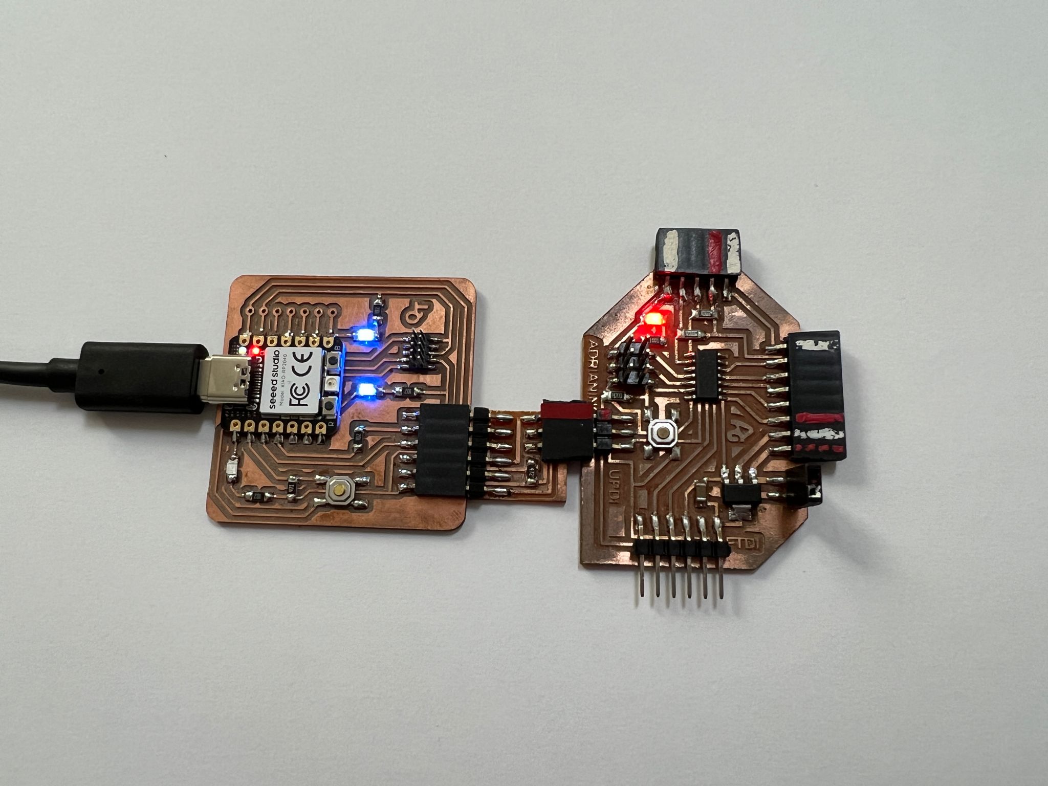
You can use the UART connector as it is, but it's also a nice way to flash a UPDI target (ATtiny 1,2 series and AVR Dx). You can either use a UART to UPDI + VCC connector, or design your target with an embedded 4.7k resistor between TX and RX:
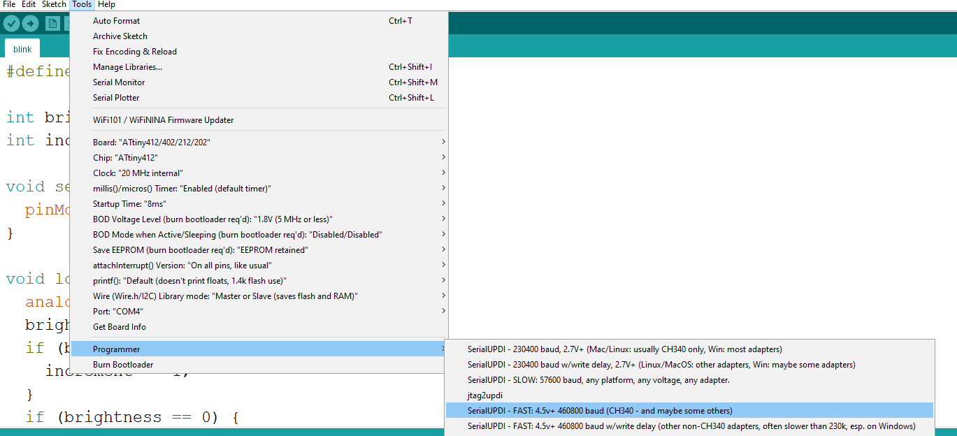
To flash the target through the Arduino IDE, first install the megaTinyCore, which comes with all needed tools. Select one of the SerialUPDI options, and make sure to select the port that corresponds to your programmer.
If successful, the output should look like this:
Sketch uses 616 bytes (15%) of program storage space. Maximum is 4096 bytes.
Global variables use 14 bytes (5%) of dynamic memory, leaving 242 bytes for local variables. Maximum is 256 bytes.
SerialUPDI
UPDI programming for Arduino using a serial adapter
Based on pymcuprog, with significant modifications
By Quentin Bolsee and Spence Konde
Version 1.2.3 - Jan 2022
Using serial port COM4 at 460800 baud.
Target: attiny412

...

Writing from hex file...
Writing flash...
[==================================================] 10/10
Action took 0.52s
Verifying...
[==================================================] 2/2
Verify successful. Data in flash matches data in specified hex-file
Action took 0.08s
Here you can see a video of the programming of an ATtiny412.
You can also program the Adrianino using the Serial UPDI + VCC module.
Linux UART Target Issues
There are know issues with Linux we discovered during the Fab Academy Instructors Bootcamp 2024 (ask Kris, Henk, Adrian).
Problem
When using Arduino with megaTinyCore:
- Board: ATtiny412, ATtiny1614
- Port: /dev/ttyACM0 (you may have different value)
- Programmer: any SerialUPDI option
The pymcuprog fails to communicate with ATtiny. If you see the following message, proceed to the Solution section.
pymcuprog.pymcuprog_errors.PymcuprogError: UPDI initialisation failed
Solution
The megaTinyCore Arduino core uses its own (older) version of pymcuprog. The issue we are experiencing seems to be an issue of that older version. To solve it, you need to install the latest version of pymcuprog, which at the moment of writing this is 3.16.8.40.
First, open Terminal and try the command below to see if pymcuprog is already installed.
pymcuprog --version
You should see the following in case you have it installed.
pymcuprog version 3.16.8.40
If you do not see the message with a version, you need to install it. If not, proceed with following steps.
1. Install python3 and pip
Make sure you have Python 3 installed.
python --version
You should see an output similar to the one below.
Python 3.10.12
If you do not see it, you need to install Python 3. On Debian and Ubuntu systems you can do with a command like the one below.
sudo apt update && sudo apt install python3
You also need to make sure that the Python Package Manager (pip) is installed.
sudo apt install python3-pip
2. Install pymcuprog
At this point you can use pip to install pymcuprog (Python MCU Programmer) utility.
pip install pymcuprog
Verify that it worked, by requesting its version.
pymcuprog --version
If you see the following output, you should be good to proceed.
pymcuprog version 3.16.8.40
3. Determine .hex File Location
- Go to Sketch > Export compiled Binary.
- Go to Sketch > Show Sketch Folder to find your
.hexfile. - Navigate to the folder using Terminal.
4. Program the Board
Depending on your chip, replace -d attiny1614 with your device (such as -d attiny412). Also make sure that /dev/ttyACM0 is the serial port of your programmer. You can see the name of it in Arduino IDE under Tools > Port.
pymcuprog write -t uart -u /dev/ttyACM0 -d attiny1614 -f BlinkATtiny.ino.hex --erase --verify
In the command line above, we are asking pymcuprog to write our program BlinkATtiny412.ino.hex using -t uart communication type via port -u /dev/ttyACM0 for the device type -d attiny1614. We additionally ask to --erase the previous program and to --verify that the chip, indeed, has been programmed.
You should see an output as below.
Connecting to SerialUPDI
Pinging device...
Ping response: 1E9422
Erasing device before writing from hex file...
Writing from hex file...
Writing flash...
Verifying flash...
OK
Done.
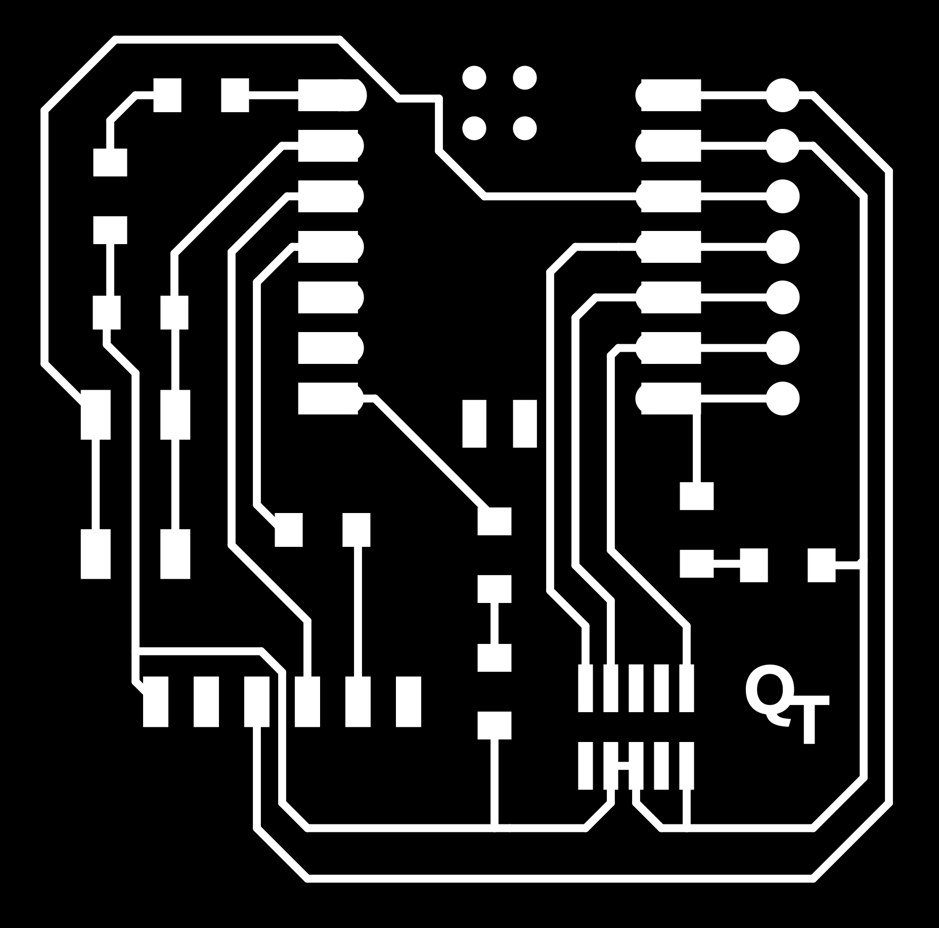
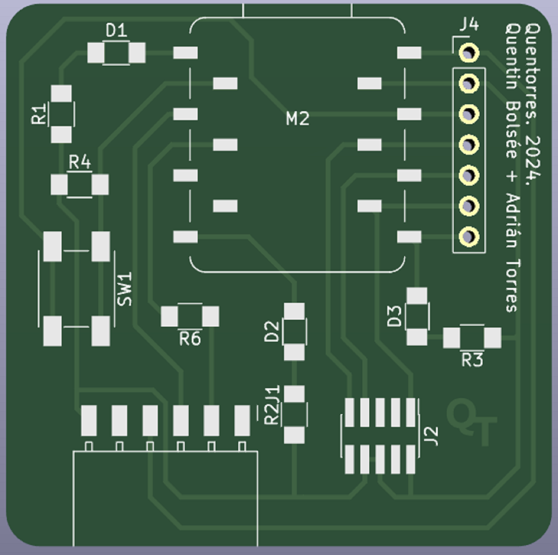
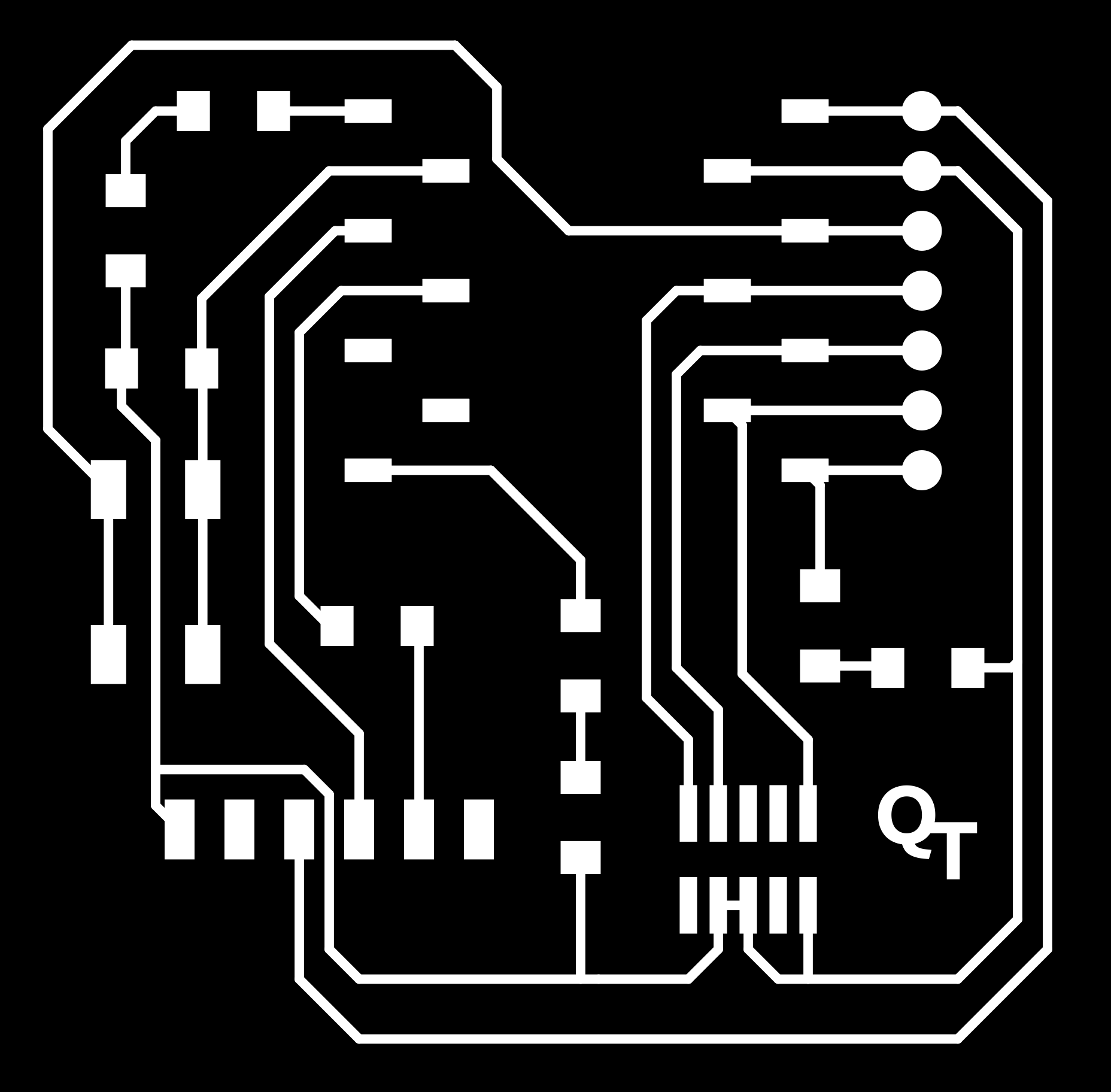
PNG renders
| Composite | Traces | Drills | Interior |
|---|---|---|---|
 |
 |
 |
 |
 |
 |
 |
 |
License
This project is provided under the MIT License.