Instructor Bootcamp 2024
Creating low cost solder stencils for reflow
Leen, Henk, Neil, Jean-michel
Q - can you create low cost solder stencil with cheap polycarbonate materials, a low cost (<500 USD) mill and low cost (~1USD) end mills
A - Yes, but you need the exact right settings.
General tips and tricks to get good results
Here is a short list of things to do and not to do when milling, using the stencil, and reflowing the paste -
milling
- Tighten all the fasteners on the machine really well.
- Make sure the milling bit is inserted far enough into the collet, so the entire collet is filled before clamping down.
- Old (>10Y) copper can create less acceptable results
- UGS can glitch when you use the computer for something else during milling, so best not to.
using the stencil
- Hold down the stencil firmly, and align it well
- Solder paste is toxic, when cleaning the stencil make sure you clean your hands and spaces really well
reflowing the paste
- You cannot use a hot plate or oven with FR1 or FR2 (although people have gotten acceptable results with FR1 in an oven, it simply turns brown)
- Don't incline a hot air gun when you are close to the board - you can blow off components
- Ventilate the space really well, or use a filter, and use lead free solder paste
- Some solder paste needs to stay refridgerated
Equipment and material
We are using a Lunyee 3018 Pro Max and a 500 Watt Daedalus Spindle - (For buying in Europe please check on Alibaba and/or local Amazon) for milling the FR1 and the plastic.
For the boards we are using FR1, and low cost 30 degrees v-bits from Genmitsu - you can also use the 0.1MM end mills from the inventory, but they are much more expensive.
The plastic we use for the solder stencils is impact resistant polycarbonate film - For larger traces you can use the 0.254mm / 0.01" thick version, for smaller footprints (i.e. 0.5mm pitch) you can use the 0.127mm / 0.005" thick version.
And we use Lead Free No-Clean Solder Paste and a cheap heat gun for the reflow - you can also use an oven or if you use commercial boards, a small hot plate
Setup and configuration of the Lunyee mill
The Lunyee 3018 Pro mill comes with a standard 500W spindle, which (for whatever reasons) doesn't do the trick - you'll need to buy the Daedalus spindle seperately, and use it with the machines. The mill is build well, and is very sturdy, but it is important to tighten ALL the nuts and bolts really well before using it. After running the machine a few times, go back to all the fasteners to check.
The mill comes with a 32 bit controller board, and a 48V power supply - which you should not connect to the 'power inn' noted on the datasheet, which takes 24V (Jean-michel can testify it makes a satisfying popping noise and produces pretty smoke if you do this anyway, and the controller can be laid to rest for eternity after such an action).
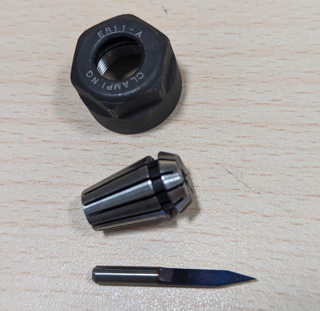
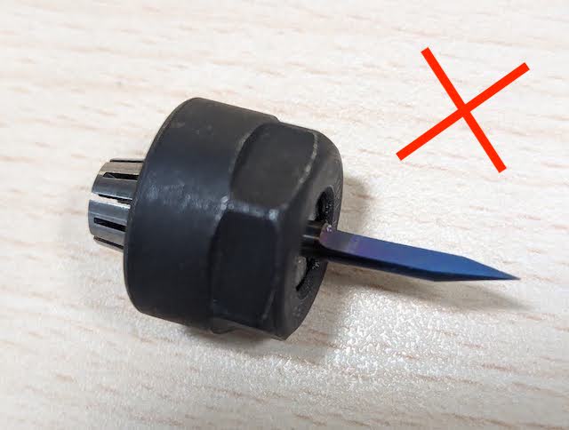
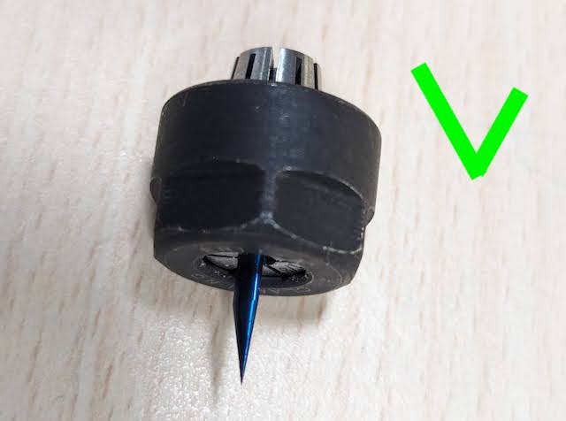
The low cost v-carve bits have a relatively short shank, and if they are not properly inserted into the collet, create significant vibration, making it impossible to properly mill boards. Make sure they are inserted in such a way that they fill the collet completely. Note that you normally NEVER want to insert a tool past the cutting edge, but in this case it's the least worst solution...
| The dissasembled setup | Wrongly inserted | Correctly inserted |
 |
 |
 |
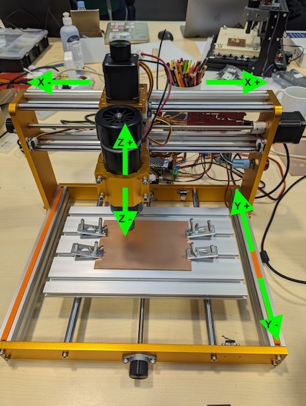
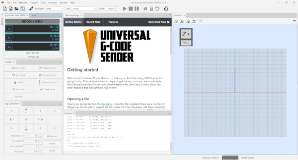
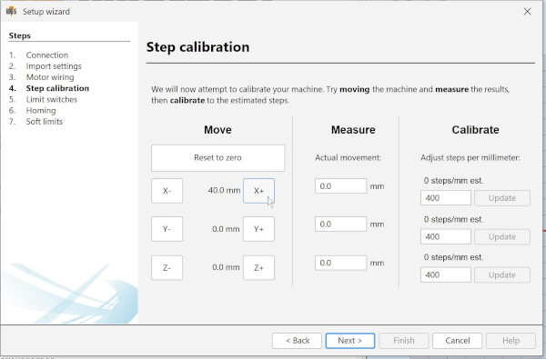
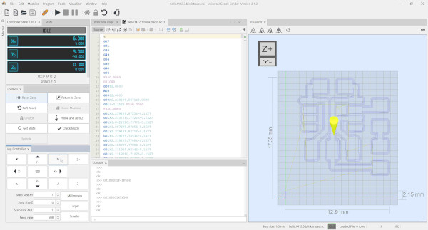
Before using the Lunyee mill, you have to make sure it's set up properly - we will be using UGS for that. Note the orientation of the axis in the image below
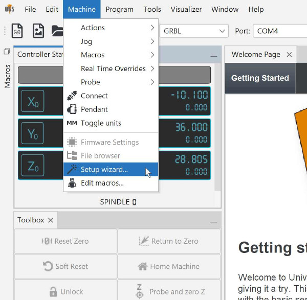
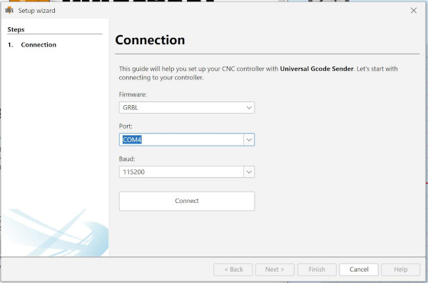
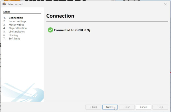
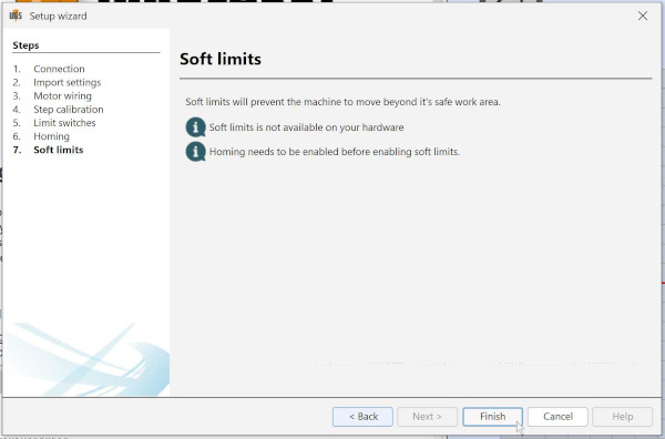
To set up, first open up UGS, and then go to 'Machine' > 'Setup wizard'
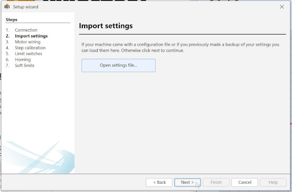
Run through the setup wizard, choosing the right port, and ignoring the 'import settings'
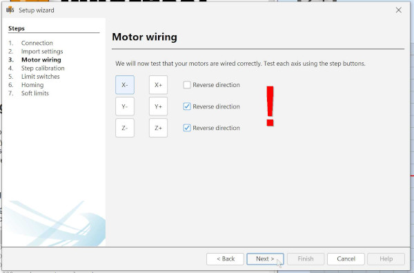
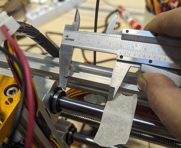
Check the correct orientation of the axis (see the image above) and propely calibrate the steps, by moving the axis, measuring the actual movement, and adjusting if needed
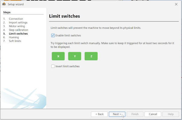
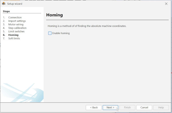
You can activate limit switches and homing if you like, but it is not functionality that we use for this tutorial
Milling PCB stock
As mentioned before, the Lunyee mill needs an upgraded spindle, and you need to make sure everything is nice and tight and your bit is inserted properly. With that said, after some experimenting we recommend using the settings below. We use Mods (community edition) to generate the files, and Universal G-code Sender to send the files to the machine.
Preparing the files with Mods community edition
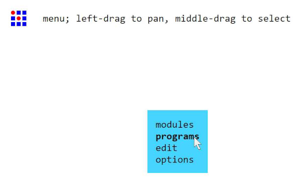
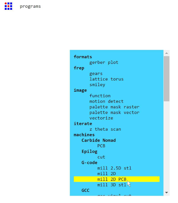
Open up the Mods community edition by navigating to https://modsproject.org/ and open the 2D PCB program (in the g-code list) by right clicking and going 'programs' > 'open program' > 'G-Code / mill 2D PCB'

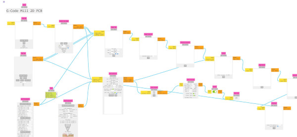
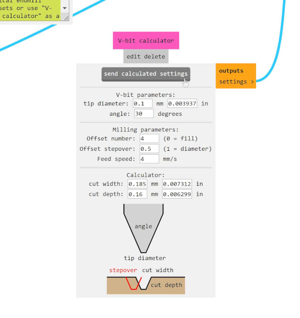
Open the traces file for milling the copper, and use the following settings in the V-bit calculator and click 'send calculated settings'
- 0.1 tip diameter
- 4 Offsets
- 0.5 Offset stepover
- 4 Feed speed
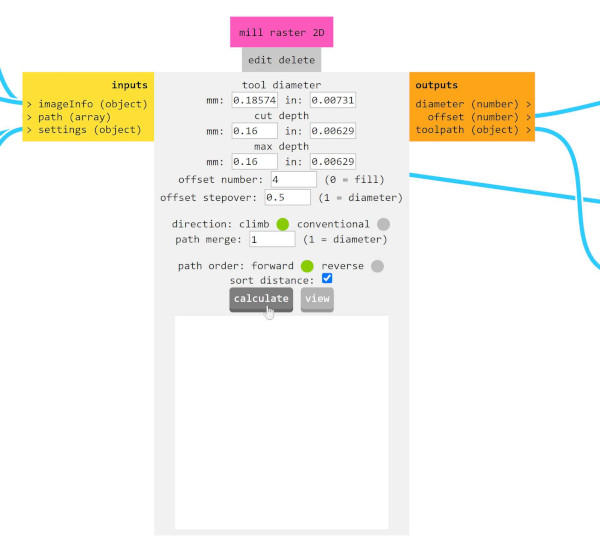
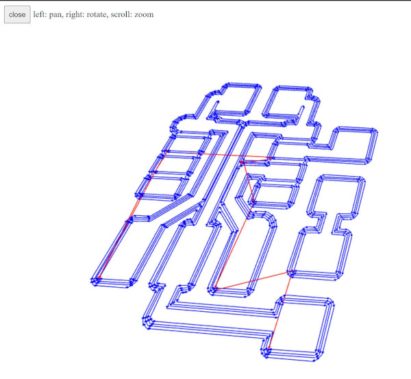
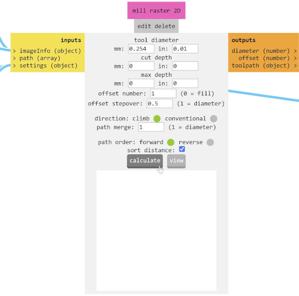
Make sure the values have been correctly transfered to the 'Mill raster 2D' dialog, and click 'Calculate' - this will save the .nc file, and open a new tab with a 3D view of the toolpath. Re-name the saved file to make sure you know which one it is.
Repeat the previous steps with the outline file for cutting out the board, using the settings below to generate the .nc file, and rename the file.
- Tip diameter - 0.1
- Offsets - 4
- Offset stepover -0.5
- Feed speed - 4
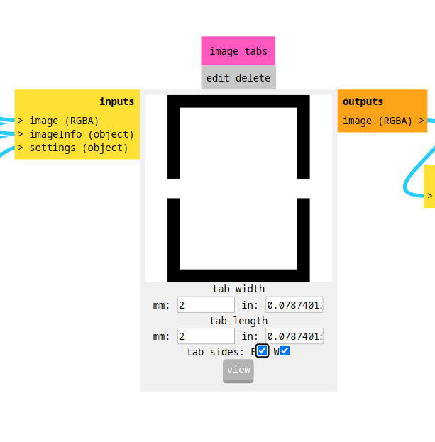
To prevent the board from becoming loose and flying away due to the rotation of the milling bit, use tabs. Go to the "image tabs" module and use the settings as in the image below.
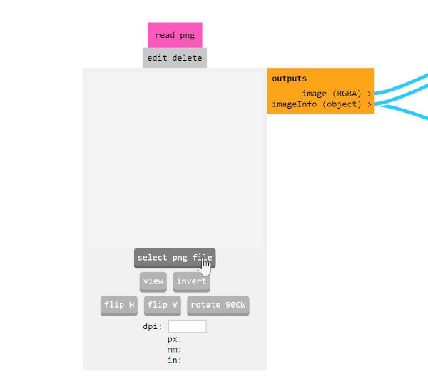
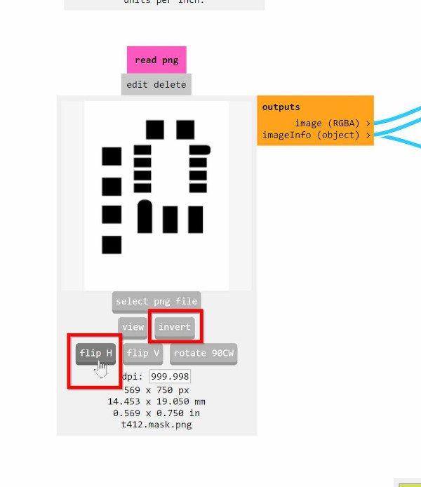
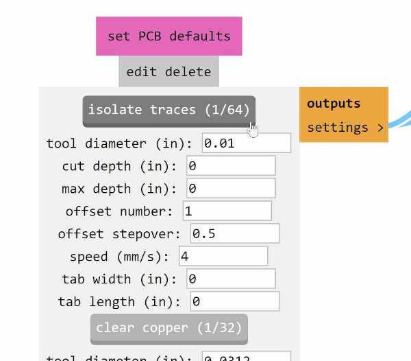
Then select the pads file for the solder stencil, and use the settings below to generate the .nc file - note that we use a different method of generating the file than we used for the previous 2 files, and the file needs to be inverted and flipped in the horizontal directions ('invert' and 'flip H' in the file open interface in mods)
- Tool diameter - 0.01
- Cut depth - 0 (zero)
- Offset number - 1
- Speed - 4
Once you input the right settings, click 'isolate traces' and 'calculate' to generate the .nc file - rename the file.
You now have 3 .nc files - 1 for the traces, 1 for the outline to cut out the board, and 1 for the solder stencil. The next steps explain how to mill the copper, after which we move on to milling the plastic.
Milling
We mill the copper with the spindle at ~40% of it's maximum speed.
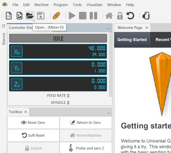
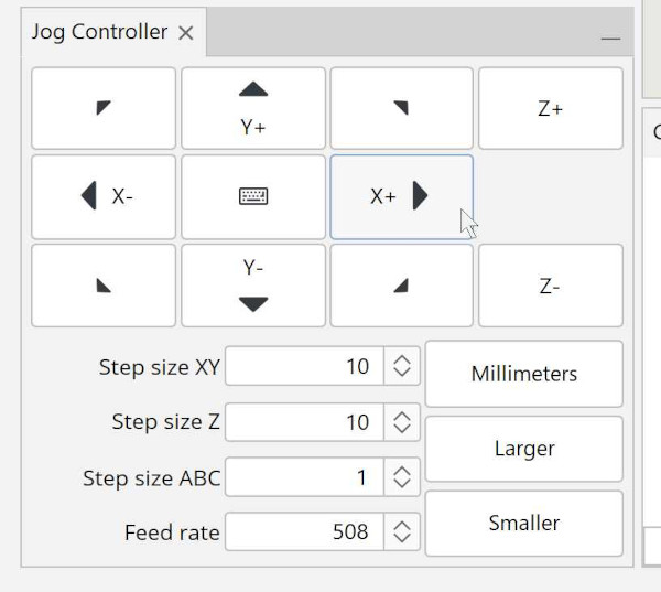
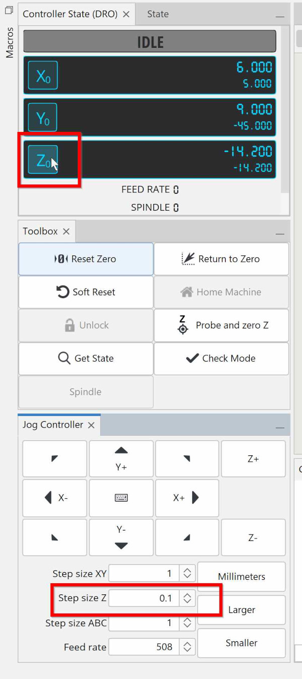
Open the traces file and Use the Jog controller to move the tool the to X and Y location you can to start milling at, knowing that point will correspond to the lower left corner of your file (assuming you have the right orientation of your axis). Click the X0 and Y0 buttons (next to the location shown) to zero both axis
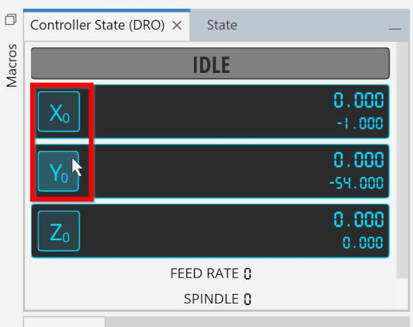
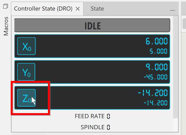
Move your tool in X and Y to the approximate center of your file, and zero the Z axis by lowering the tool down very slowly (0.1 mm steps) while moving a small piece of paper underneath it, untill the tool grabs the paper. Now click the Z0 button (next to the location shown).
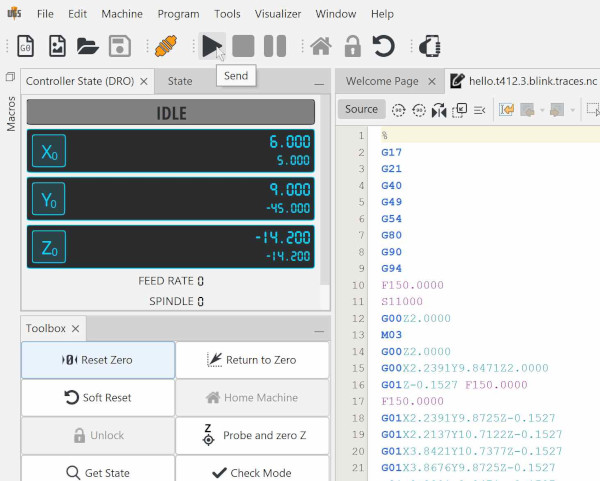
Make sure the bit is tightened properly, no tools or other objects are on the machine, and everything is safely set to start. CLick the play symbol to start the milling process.
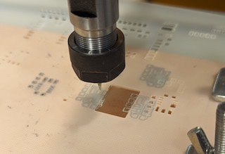
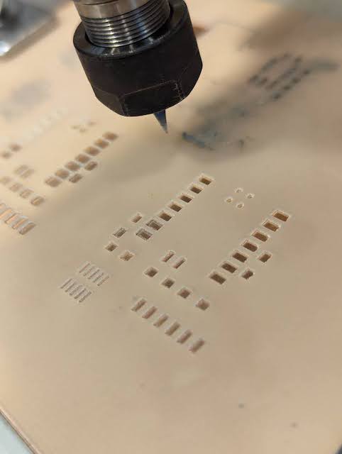
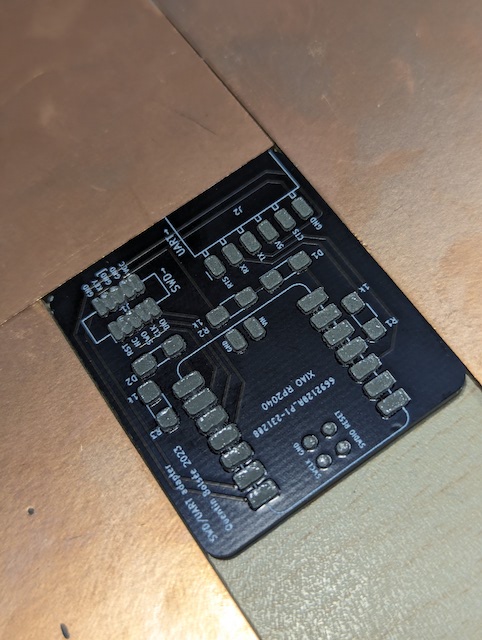
Once the process has completed, move the spindle out of the way, vacuum up any dust and loose parts and inspect your board. The result should look similar to the image below (clean traces, no ragged edges etc.)
Change the bit to a 1/32 (or similar) bit for cutting out the board, make sure to NOT change the X and Y zero location Zero the new bit next to where the file is placed on your board, and click Z0 (make sure to NOT change the X and Y zero!)
Load the file for cutting out the board, and make sure everyting is set up safely for milling, and click the play symbol again to start the milling process. Once the process has finished, vacuum up the dust (while making sure you do not vacuum up the board!), take out the board, and put it asside.
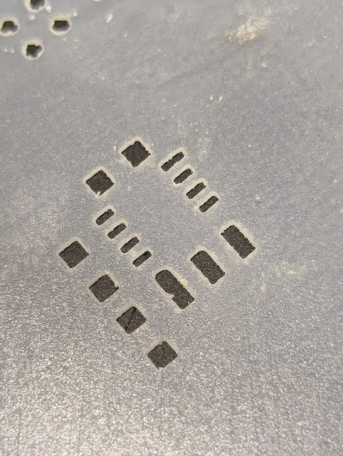
Milling solder stencil
Mill the plastic with the spindle at 100% speed.
After experimenting with different thicknesses of material, we found out that the best solution is achieved using 0.254mm / 0.01" thick polycarbonate, which is thick enough to have proper stiffness, and thin enough to not leave too much solder on the pads.
For components with smaller footprints (i.e. 0.5 mm pitch) the 0.254mm thick material does not work if you are using v-bits, because the kerf becomes to big - for those you can switch to thinner polycarbonate, which you'll need to fix with double sided tape
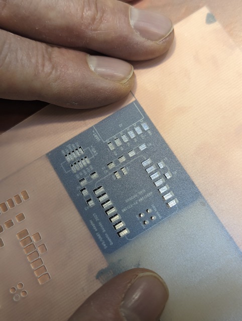
To mill the stencils, you will need a file with ONLY the pads (no traces or holes) which you want to invert - since we will be milling with a v-bit tool, the kerf will be slanted, and we want the larger opening towards the bottom, so we don't pull up the solder paste when removing the stencil.
Milling the stencil is the same process as milling the copper, but we recommend zeroing the Z on the copper plate which is below the polycarbonate (so you want to cut a hole in it before clamping it down) and setting the Z-depth when milling to 0 (zero). See the screenshots below for the correct settings in mods.
Applying the solder with the stencil
Make sure you have lead free solder paste, and if it's the kind that needs refrigeration, take it out of the fridge just before you will use it, and make sure to put it back once done.
Fix the milled board to a flat surface and fix boards of the same thickness around it
Align the stencil with the board, and tape down one of the sides - you will lift it up pivoting on the tape once you are done.
Add a generous amount of solder paste to the board, while firmly holding down the stencil - you want to be 2 people to properly do this and the next steps
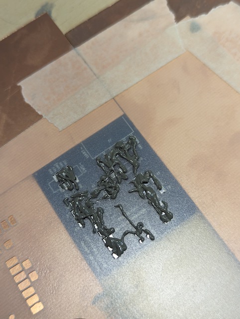
Push the solder paste into the holes of the stencil using a dence squeegee (or a credit card) and swipe over the complete board while pushing down

Scrape over the board with the edge of the squeegee/card, until there is only solder left in the holes, but the rest of the surface is clear of paste
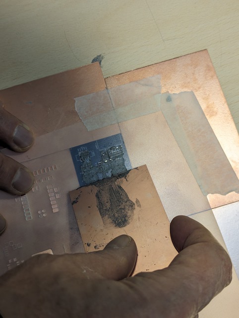
Carefully lift up the stencil on the opposite side of the tape, and remove it completely - it's a good idea to clean it immediately with water, for later re-use.
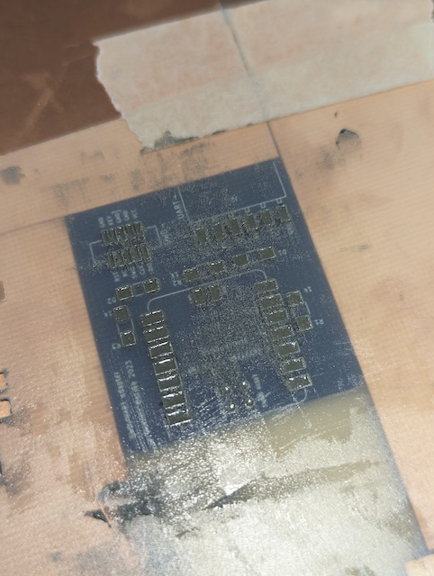
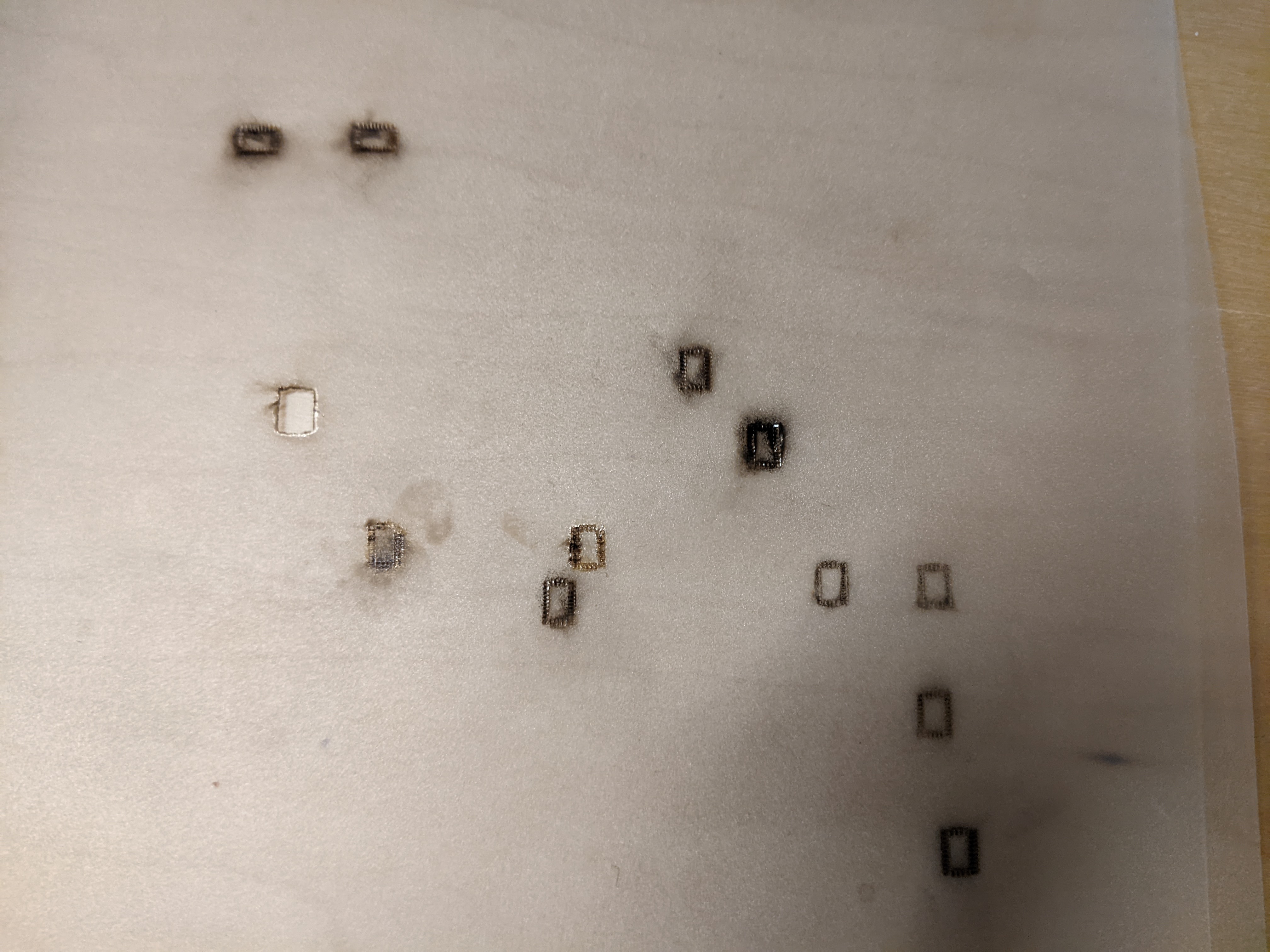
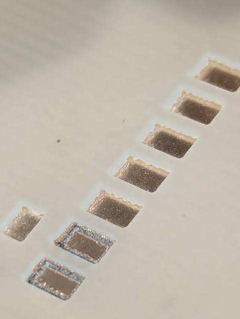
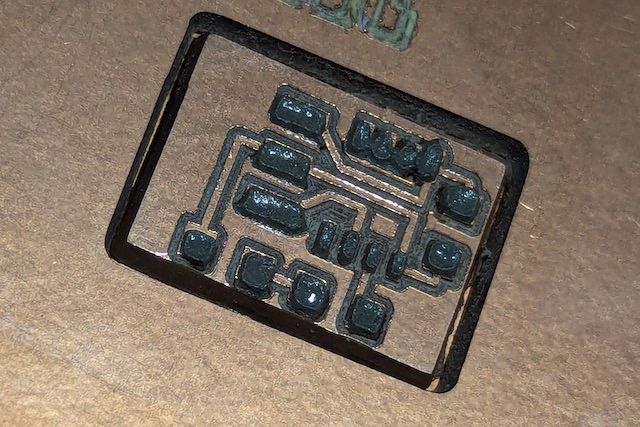
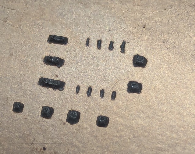
Check the images below for a board with too much paste, and the right amount.
Too much solder paste on the left, the right amount on the right -
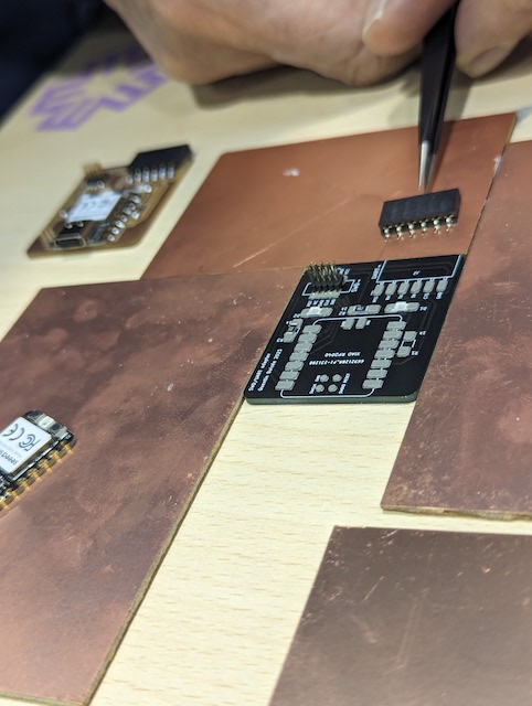
Done! You can now move on to stuffing the board, and reflowing the solder.
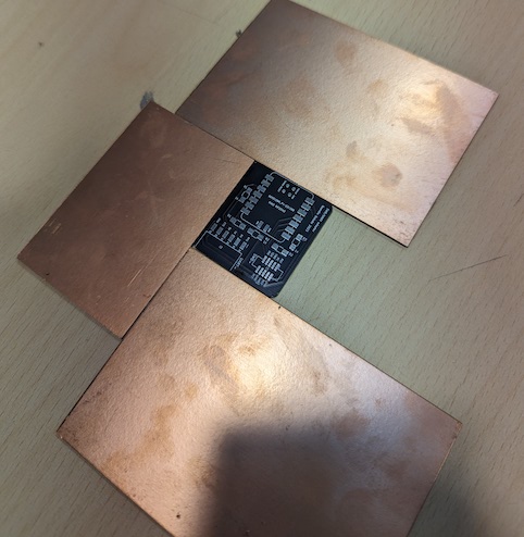
Stuffing the board and reflowing the solder
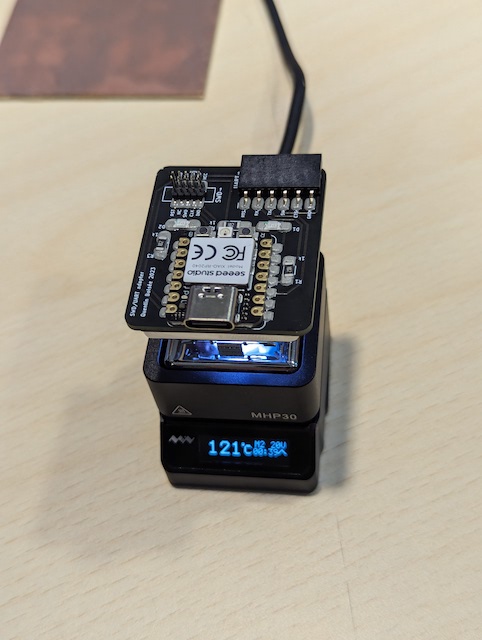
If you are using FR1 or FR2, you have to reflow with a hot air gun, or using an oven (which will still make the bottom of the board brown). If you ahve a commercial board (like in the pictures) you can use this small hotplate.
To further illustrate the process, here are some video's -
Done ! (and next steps)
Once you are done, Do a Dance! Next steps are trying this with smaller footprint components, and other cutting processes..
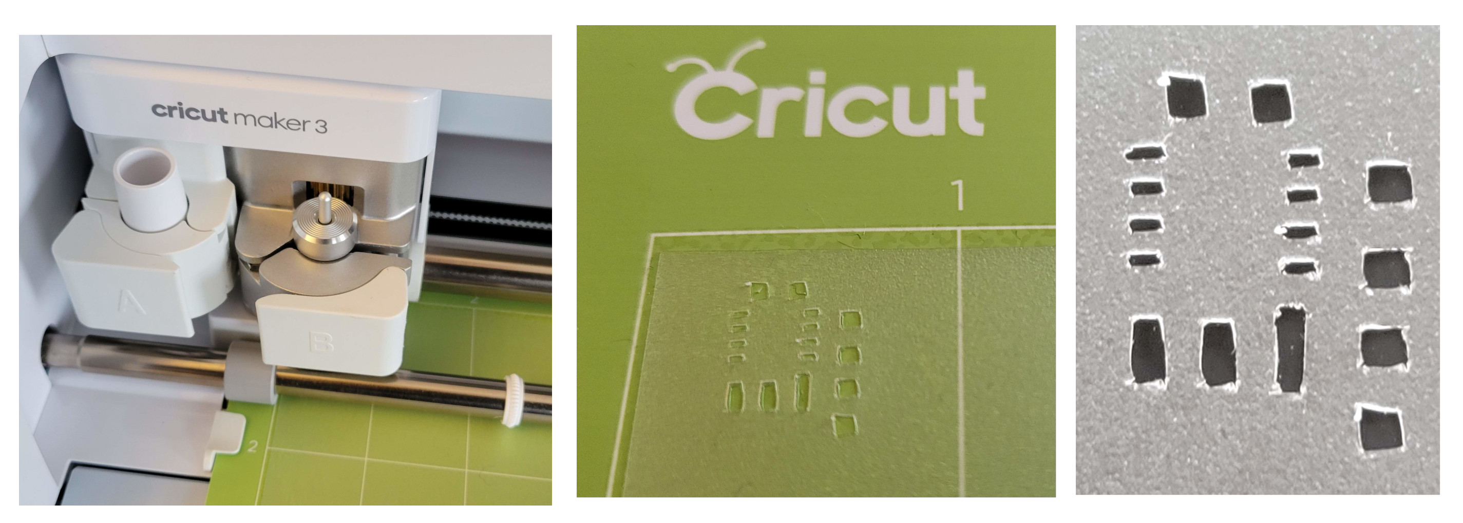
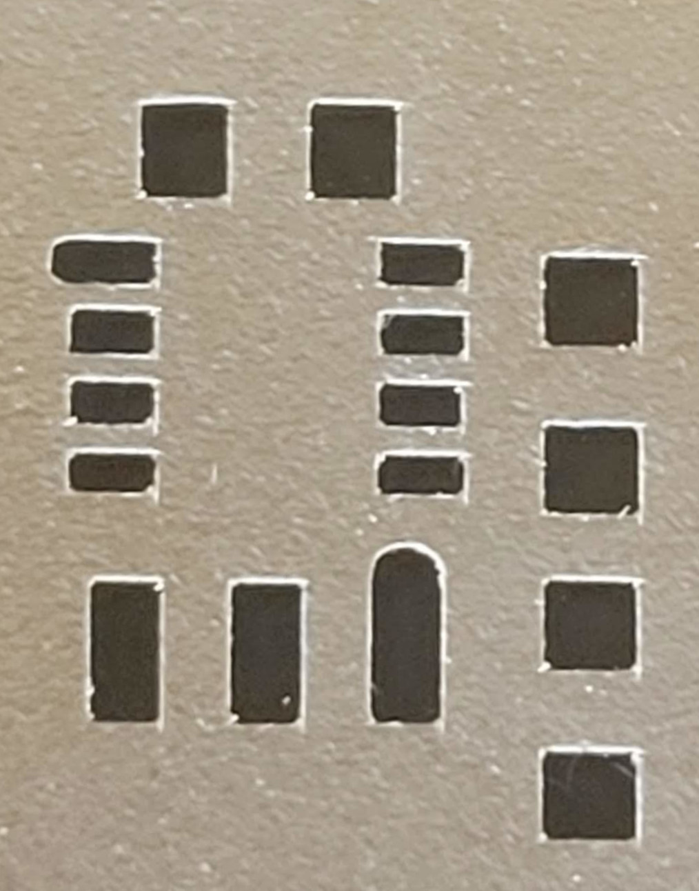
Cricut test
0.005" polycarbonate, fine point blade, transparency settings
Poor geometry control with the drag knife, will investigate the driven knife
0.005" polycarbonate, driven knife blade, StrongGrip map, 1/16 balsa setting, stop after 2 passes. Looks better:
laser test
xTool S1, polycarbonate, charring