BLDC Modular Thing
- Svavar Konráðsson (Fab Lab Ísafjörður, Iceland)
- Þórarinn Bjartur Breiðfjörð Gunnarsson (Fab Lab Ísafjörður, Iceland)
Description
This is a new Modular Thing that you can use to easily control a sensored brushless DC motor. The motor knows its position and automatically returns to it when disturbed. The board works well and it can be milled in any Fab Lab!
The board requires a separate power supply for the motor. You could use a bench power supply or hack USB power with a tiny412, for example.
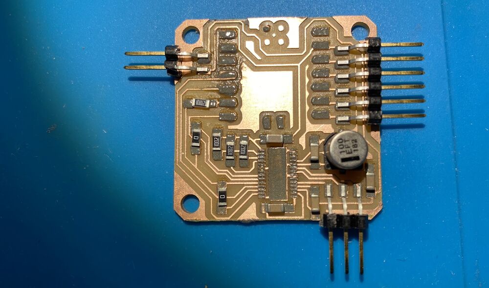
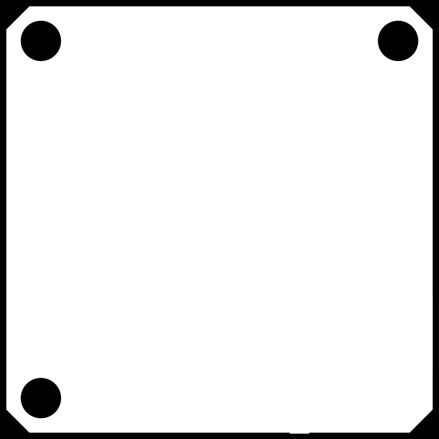
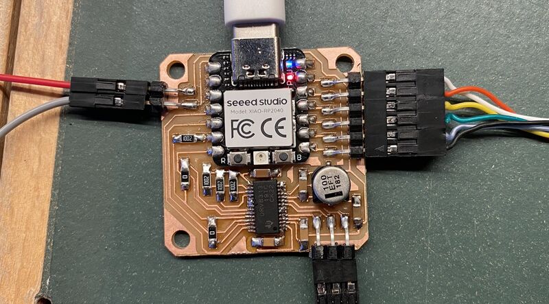 Three pins for the motor are on the bottom of the board and six pins for the sensor are on the right side. On the left side are two pins for 8-60V power input.
Warning
You need a V-bit to mill this board. It's within the reach of Fab Academy students, but be ready for some experimentation with settings for the V-bit. This board was the first customer for the new PCB workflow that was created during the instructor bootcamp. That was how we finally managed to make the circuit.
BOM
| Part | Count |
|---|---|
| GM2804 Gimbal Motor w/Encoder | 1 |
| Xiao RP2040 module | 1 |
| DRV8313 motor driver | 1 |
| 100 nF capacitor | 4 |
| 1 uF capacitor | 1 |
| 100 uF bulk capacitor with 6.3 mm diameter | 1 |
| 0 Ohm jumper resistor | 2 |
| 10 kOhm resistor | 4 |
| 2 pin horizontal SMD pin header | 1 |
| 3 pin horizontal SMD pin header | 1 |
| 6 pin horizontal SMD pin header | 1 |
You aren't restricted to using the GM2804 gimbal motor with integrated AS5048 encoder. You can also use any of the other iFlight gimbal + encoder combos. And if you're willing to modify the code a little bit, you can also use any of the other sensors that are supported by the SimpleFOC library.
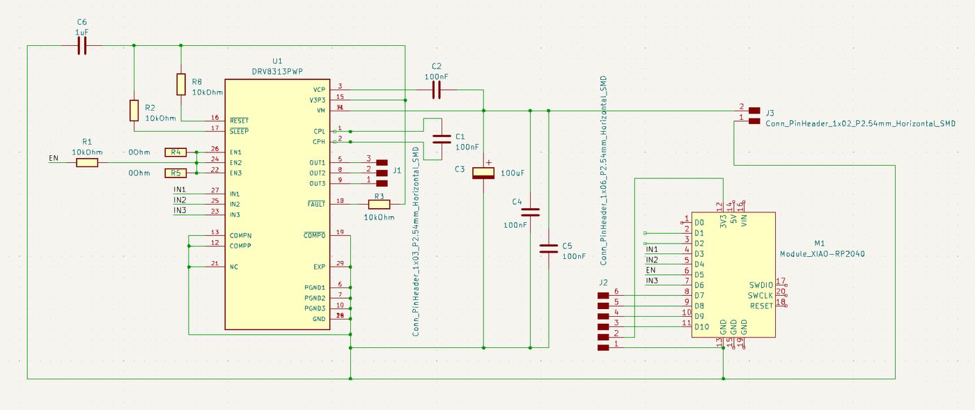
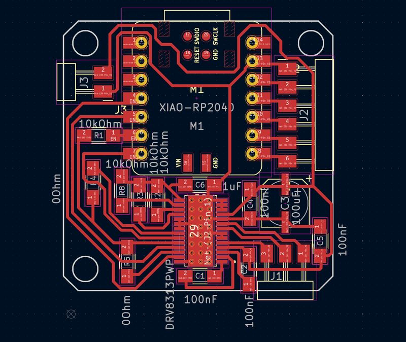
Schematic and PCB layout
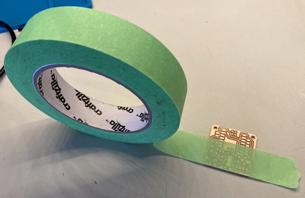
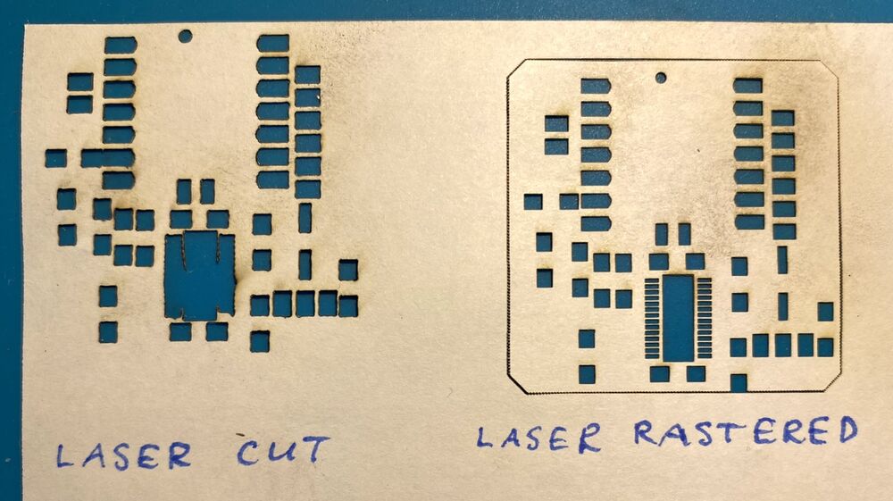
PCB milling (this section refers to a previous board design that didn't work)
Several attempts were made to mill the circuit on the Modela MDX-20, but with no success. The flat V-bits kept tearing up the traces. But when the new PCB and solder mask method had been demonstrated at the bootcamp, that method was used successfully to mill the BLDC board.
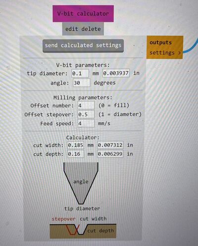 30° V-bit milling settings 30° V-bit milling settings |
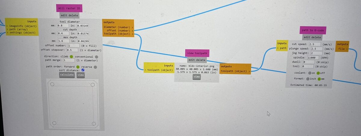 Outline milling settings with 1/32 inch milling bit. Outline milling settings with 1/32 inch milling bit. |
|---|---|
| Settings in Mods Community Edition. |
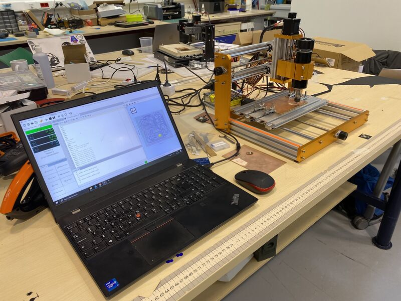 The G-code from Mods was loaded into Universal G-code Sender and sent to the Lunyee mill over USB.
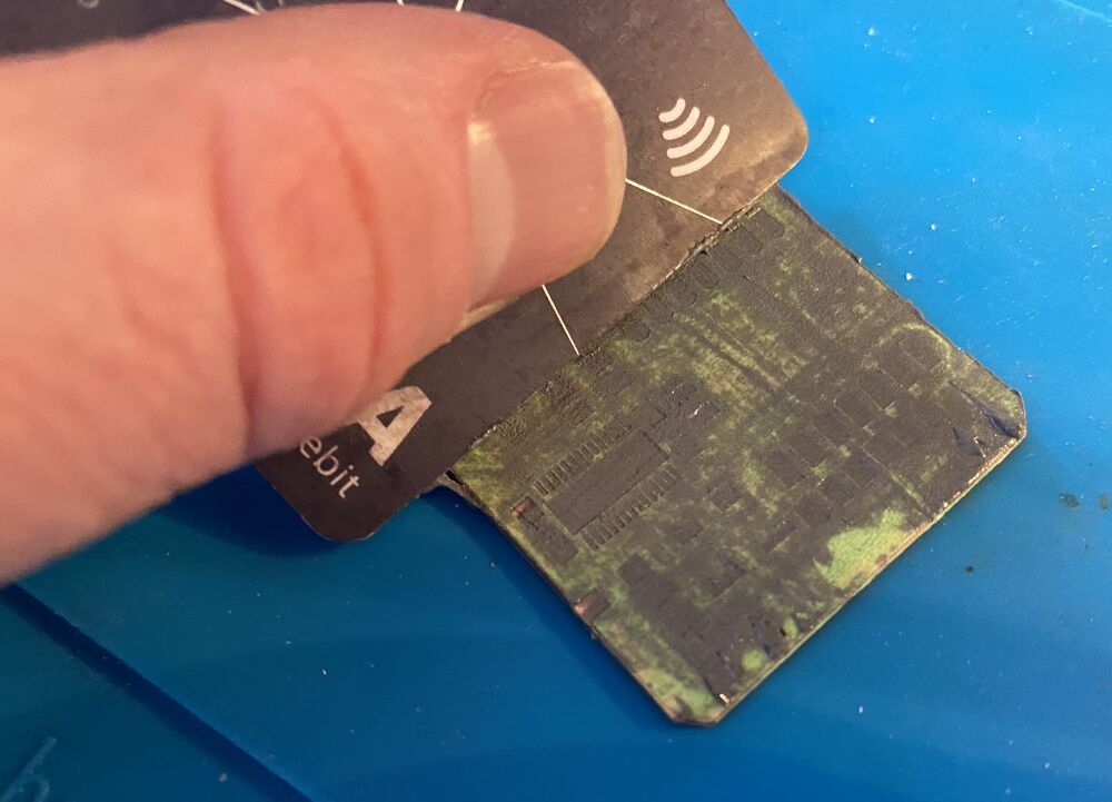
This is a bigger board than they had been testing, so we ran into the problem of the PCB bending upwards in the middle when clamped down. The first milling attempt didn't go all the way through the copper near the clamps, so in the second attempt we zeroed the Z-axis very close to the clamps. There the PCB is definitely in contact with the table and we can be sure that the V-bit will go through the copper layer everywhere on the board.
UGS milled the outline first, then the holes, so we had to stop the job. But the circuit works. Next time we'll put the holes into a seperate PNG file and mill them first.
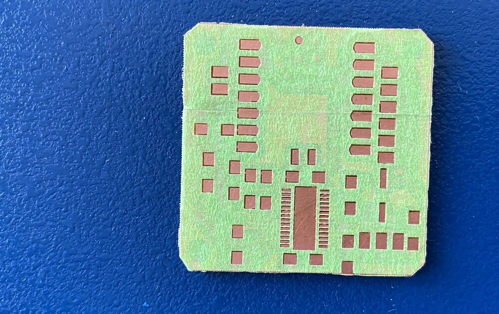
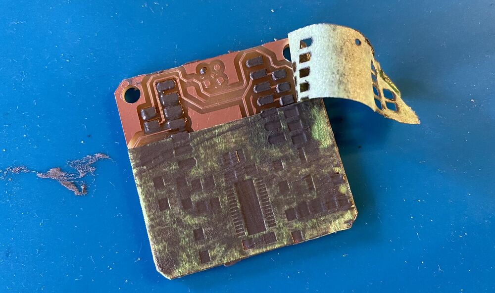
The traces still came out a little rough, but it was manageable. We tried deburring the copper first with a piece of printer paper, then with wet steel wool (which scratched the copper) and finally Yuichi gave us a fine grit Japanese sanding sponge that worked really well. This is the best deburring method we've tried by far. You wet the sponge well and sand the copper with gentle circular motions:
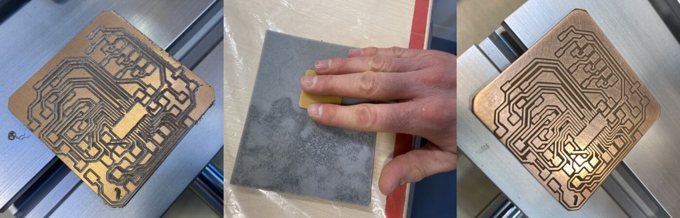 Deburring with sanding sponge resulted in a beautiful board. We should find a supplier of sponges like this outside of Japan.
We didn't have time to make a solder mask for this board, so Þórarinn hand soldered everything, taking care to put very little solder on the legs of the motor control IC. That came out really well.
A good practice after soldering a circuit is to shine a light through it from the back and see if there are any unintended solder bridges. You can expect getting a few of those between the very fine traces on this board. We discovered two solder bridges on the train back to Madrid after the bootcamp. Fortunately, Andri had brought a USB soldering iron and the train had electrical outlets, so we could remove the excess solder on the go:
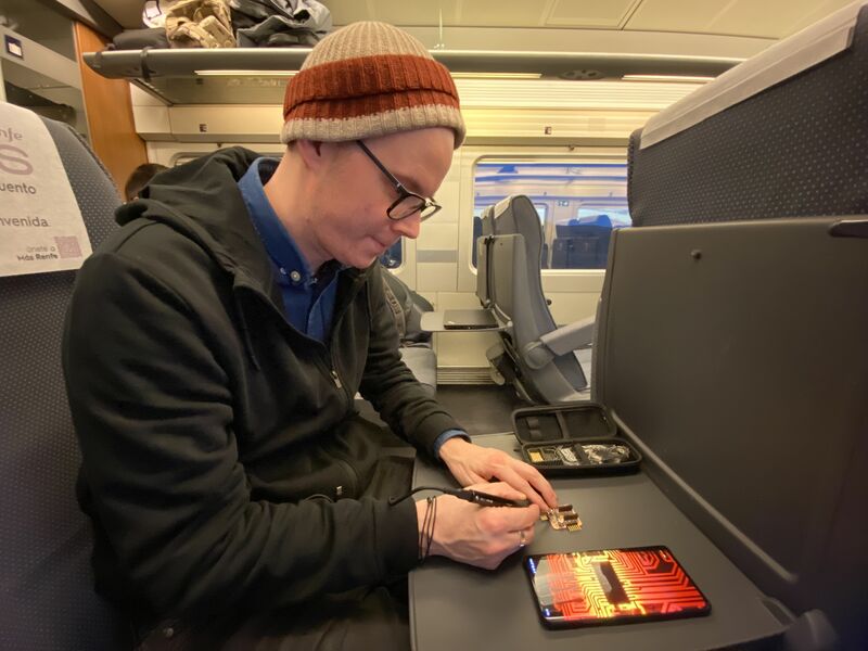 Þórarinn soldering on the high-speed train from León to Madrid.
Making the board that works
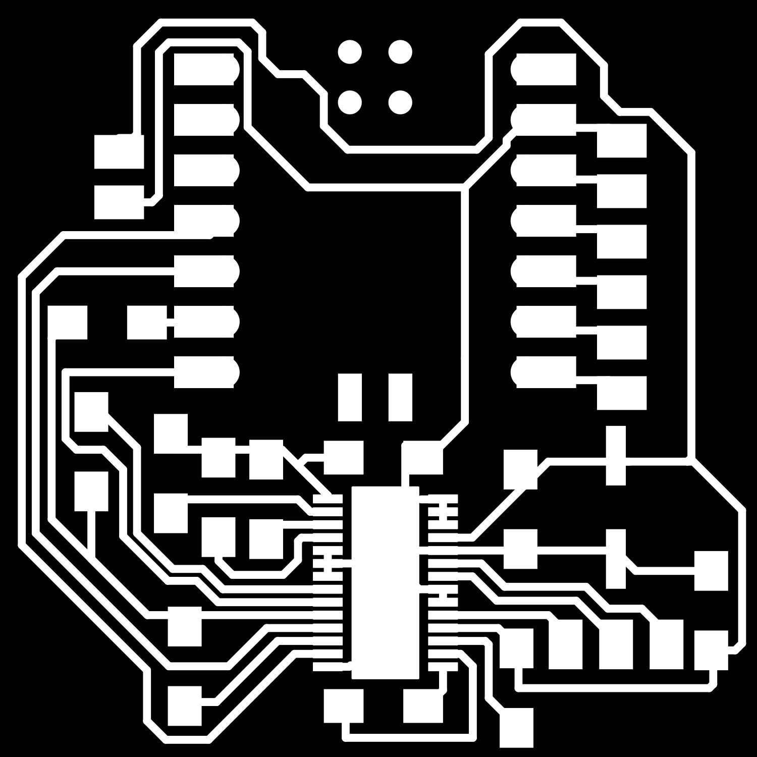
Design files
The design files have been updated to reflect the board design that works.
 |
 |
|---|---|
| PNG files for Mods CE. |
Assembly
First connect the SPI cable to the angle sensor so that the wire colors are in the following order:
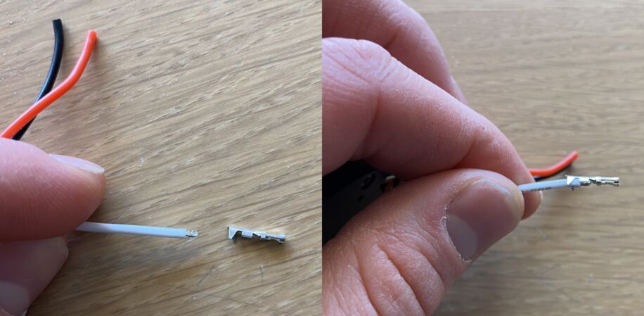
The power connector that comes with the motor is too small for the standard 2.54 mm pin headers in the Fab Lab Inventory. You need to crimp a new connector onto the motor wires. You also need to crimp a Dupont connector onto the SPI wires for the magnetic angle sensor.
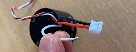 This connector doesn't fit onto the pin header on the board. Cut it off.
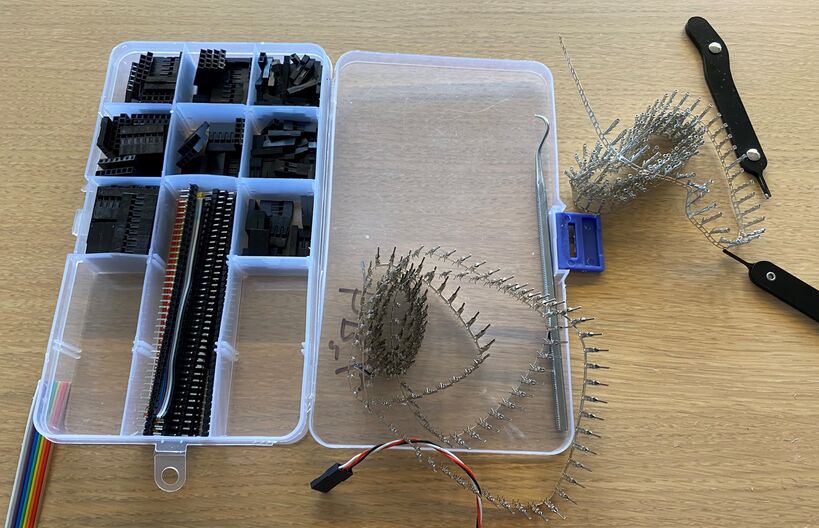 Gather three female connectors. Choose a plastic casing that fits those three.
 Align a female Dupont connector to the wire. The first crimp connection grabs the plastic cover and the second one grabs the bare wire and secures an electrical connection.
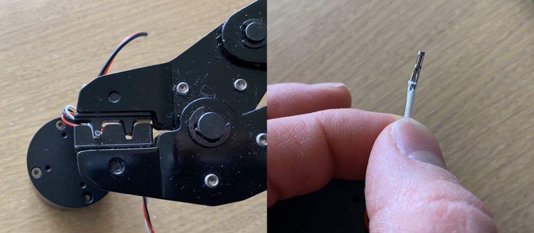 Crimp the connector onto the wire.
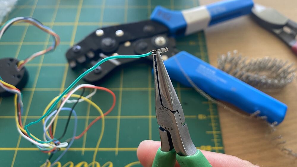
You can use narrow nose pliers if you don't have a crimping tool:
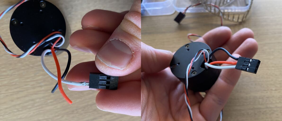 Put the connectors into the plastic casing. Triple Dupont connector, ready for service.
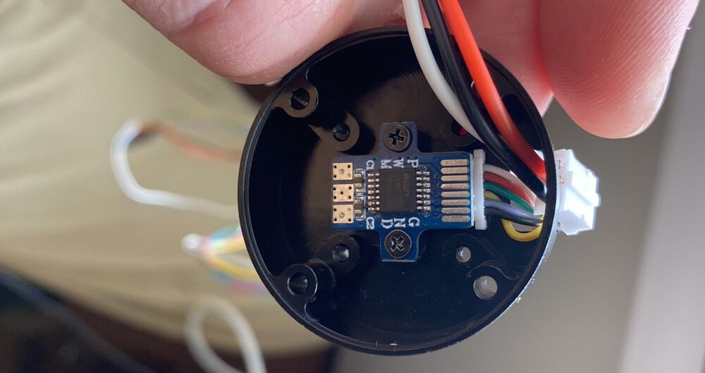
The SPI communication wires from the AS5048 magnetic angle sensor are then as follows:
white, pin 13, GND
red, pin 11, VDD3.3V
yellow, pin 4, MOSI
green, pin 3, MISO
blue, pin 2, CLK
black, pin 1, CSn
Cut the connector off the loose end of the SPI cable. Crimp female connectors onto the wires and put them into a 6-pin plastic casing in the order shown above.
How to use
- Install the SimpleFOC library.
- Connect the board.
- Upload the Arduino sketch to the board.
- Open a serial terminal and send a position command to the board.
The code accepts serial commands in the form T3.14, where T means Target and 3.14 is the position in radians. The code can control the motor but communication with the Modular Things web interface isn't working yet.