Blender for Parametric Modeling & 3D Printing
Rico Kanthatham (Skylabworkshop, Japan)
Adai Surinach (Fablab Barcelona, Spain)
Aristarco Cortes (Fablab Puela, Mexico)
Can Blender be used as a CAD software for Fab Academy?
Adai says "Yes!". He completed FA2022 using only Blender as his CAD software.
Rico says "Maybe" and Aristarco agrees. The current version of Blender features an evolution of the "Geometry Node" functionality that (probably) allows for precision "Parametric Modeling".
Why Blender (for Fab Academy)?
Blender is free and open source...and should always be.
Blender is an incredibly powerful and full-featured software, able to produce high quality renders, animations, physics simulations, etc...in addition to 3D modeling.
The 3D modeling procedure on Blender is different than the procedures of commonly used software in FabAcademy...such as Fusion 360, Solidworks or FreeCAD...that starts with a 2D sketch that is then extruded in to BREP 3D shapes. Blender 3D modeling starts with 3D meshes that are transformed, modified and (boolean) combined with others in a "non-destructive" manner. Blender 3D modeling process...especially when the Geometry Node feature is used...is similar to 3D modeling using Rhino/Grasshopper...where complex geometries can be more easily achieved efficiently.
Whereas historically, Blender was mostly used to generate virtual, artistic 3D assets and animation. It's current version makes it (arguably) a legitimate tool for generating 3D objects that can be physically fabricated (e.g. 3D printed). Moreover, we believe that Parametric modeling...required for Fab Academy...can be achieved in Blender.
Adai's Smart Citizen Enclosures
Since 1 year ago, all the 3D printed enclosures for the Smart Citizen project was designed on Blender. You can see documentation of the project here. This project is NOT parametric...but results in a dimensionally precise and 3D printable model.
Parametric Design with Blender Geometry Nodes
What are Geometry Nodes?
"Geometry nodes is a node system that allow us to procedurally control the data in a mesh or curve object."
The Geometry Node feature is a visual programming tool...that (probably) makes it possible to parametrically model 3D geometries in Blender. It is similar to geometry making using Rhino/Grasshopper.
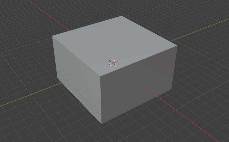
Each Blender node is a Python script function that performs some geometry modification operation, such as scaling, extrusion or boolean difference. User "built" combination of nodes (called a Node Tree) non-destructively modifies (does not permanently alter) a simple source geometry to produce a more complex output geometry. For example, starting with a basic cube, modifiers can be used to turn into a 3D printable device enclosure (like Adai's project). Parameters in the Node Tree can be saved and later modified as needed (to change the size or add new features, for example). The Node Tree itself is like a recipe and can be shared, used and modified (with different parameters) by others.
Geometry Nodes was added as a feature in Blender in August 2020, but has become a practical tool for Parametric 3D Modeler very recently. In Blender version 4.0, there are many dozen operational nodes that can be used to generate 3D output. All of Blender's nodes are listed here
More about what Blender Geometry Nodes are can be read here
Caveat > Blender's Geometry Node tools are constantly under improvement. We recommend that you get familiar with the procedure by doing some tutorials now so that you can take advantage of all the new features when they are released.
Geometry Node 3D Modeling
The following images shows a complex 3d object that was generated using Blender's Geometry Node feature.This complex shape would be near impossible to model using Fusion 360 or Solidworks. It demonstrates a modeling result that is born out of a 3D modeling procedure that is distinct in character from those typically used in Fab Academy.
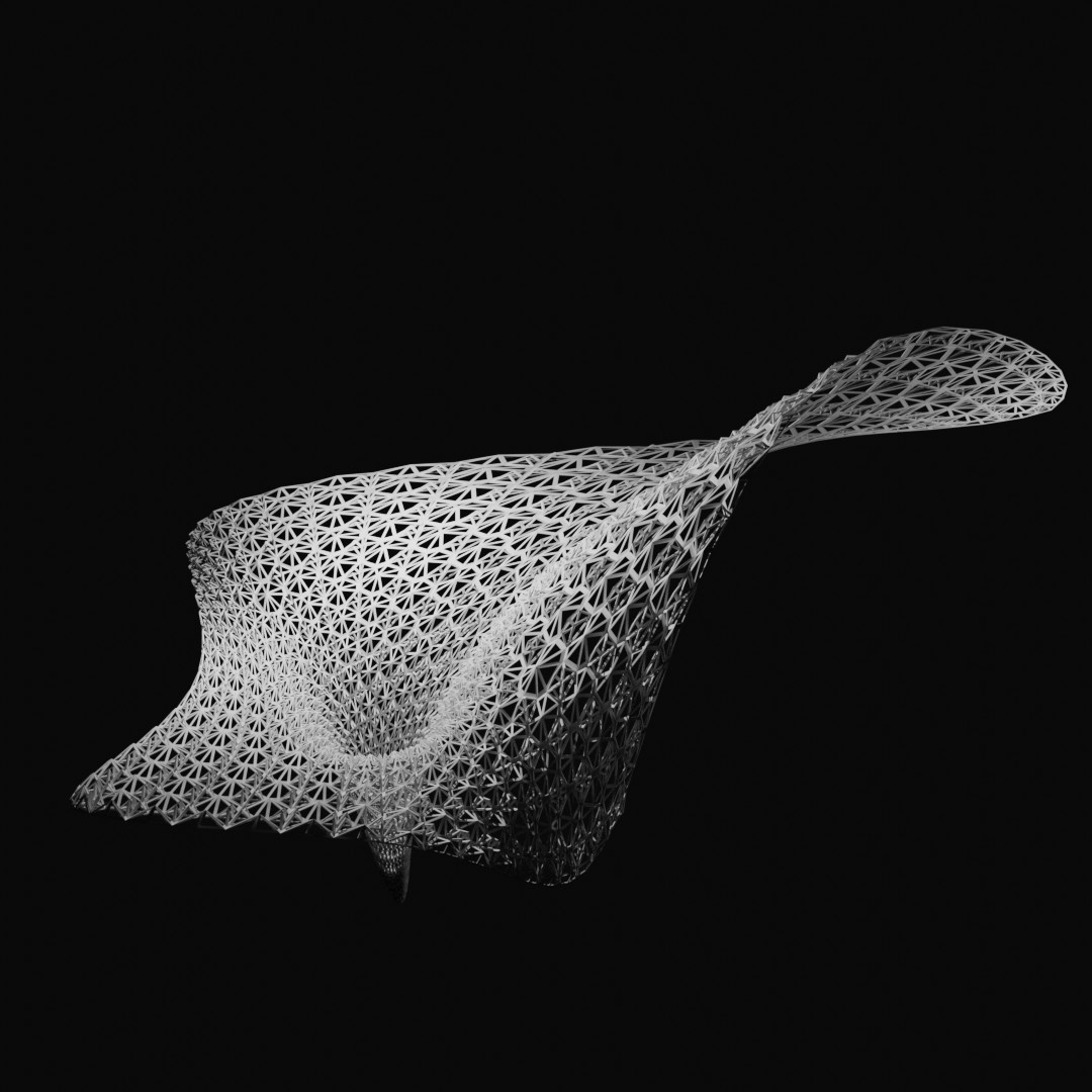
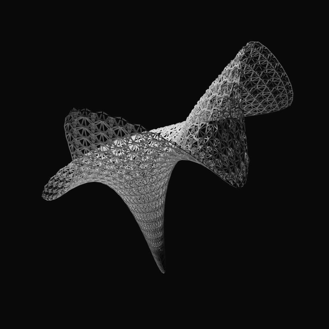
This Node Tree (comprised of 13 operational nodes...between the Input and Output nodes) was utilized to create the result is this...
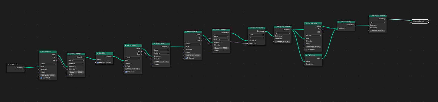
The Node Tree is similar to to Fusion's History...where each operation taken to generate to final form is recorded and each operation's parameters can be adjusted in the future to affect the final 3D result.
A video tutorial and walks through how to build the node tree to generate this shape is here.
This example is has parameters, but is not "parametric" since mathematical or constraint relationship between parameters have not been established...and there are plenty of operations that were "done by hand" and not in Geometry Nodes.
"Hello World" Blender Parametric Modeling Tutorial > Sake Cup
Setting Up Blender
- Launch Blender and select the Geometric Node workspace
- In Scene/Units > set Unit System to Metric, Unit Scale to 0.0001, Length to Millimeters
- Edit/Preferences/Add-on...search for and toggle on Node Wrangler add-on
Building the Node Tree
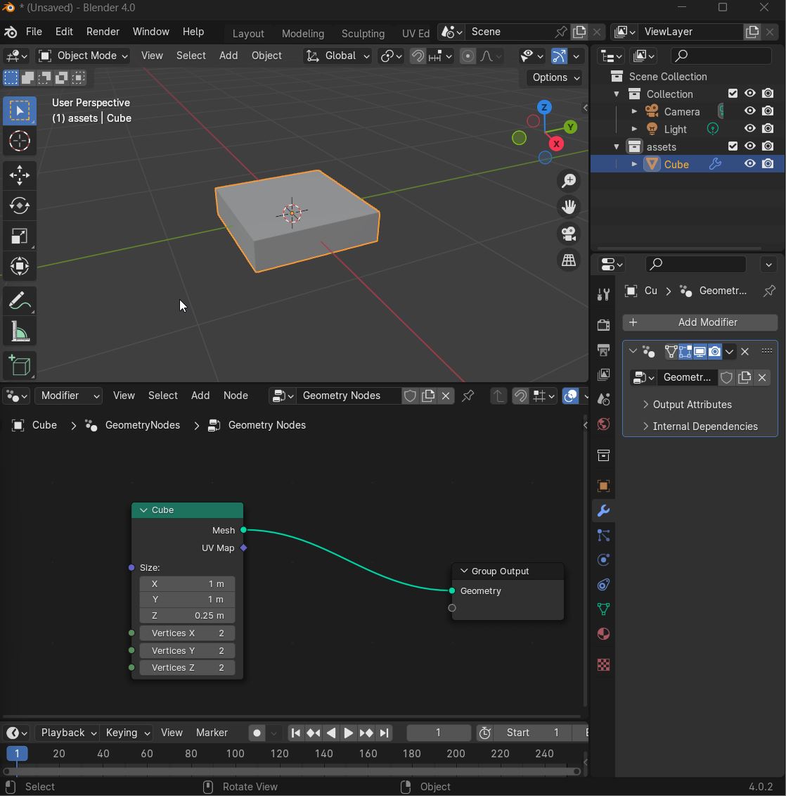
- Selecting the default cube > create a new Geometry Node tree in the Geometry Node window
- ...SHIFT+A add a "Mesh Cube" geometry
- In the Modeling Window > select and delete the default cube
Building the Node Tree > Sake Cup
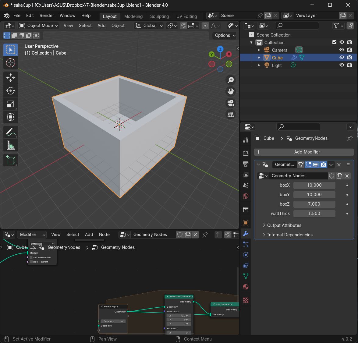
The strategy will be to make a box with adjustable XYZ dimensions (in mm). Then we will create a second box based on the dimensions of the first box...but smaller in the XY dimension by some wall thickness dimension. The second box will be used to cut a hole from the first box.
Creating a Base Box geometry
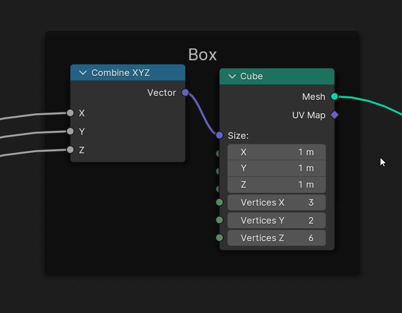
- In the Geometry Node window > SHIFT+A to add a Mesh Cube geometry
- ...SHIFT+A to add a Combine XYZ node, connect its output to the Cube geometry's Size input
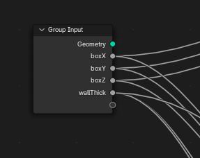
- ...SHIFT+A to add a Group Input node. This will be our parameter list. Connect XYZ input nodes to empty slots in the Group Input node...rename each of them to something sensible (ex: boxX, boxY, boxZ)
- Collections of nodes can be put into a frame so that they can be moved together...select all of the nodes making up the base box use CTRL+J to create a frame around them.
- In the Geometry Node window > press N to unhide the side menu
- ...select the frame you just created and add a lable for it in the node tab of the side menu
- ...press N to hide the side menu again
Creating a Hole geometry
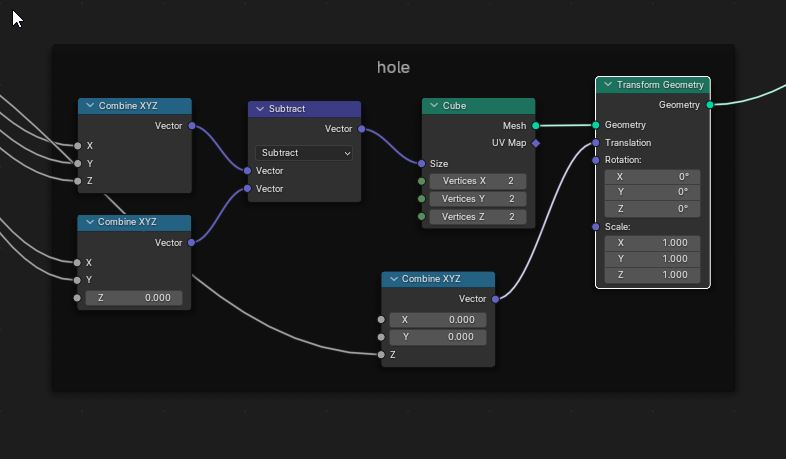
- In the Geometry Node window > select the Mesh Cube node from the previous step and SHIFT+D to duplicate the geometry
- If it is stuck in the frame...ALT+P to remove it from the frame
- ...SHIFT+A and add a Vector Math node and change the operation to subtract...connecting the node's vector output to the cube's size input
- ...SHIFT+A and add 2 Combine XYZ nodes that will be connected to the 2 vector inputs of the Vector Math node. Arrange them one on top of another
- ...for the top Combine XYZ node, connect the XYZ inputs to boxX, boxY, boxZ from the Group Input node...and the vector output of this node to the top vector input of the subtract node. The dimensions of the original will be used as the values that will be subtracted from
- ...for the bottom Combine XYZ node, connect the XY inputs to an empty connector in the Group Input node. Rename this connector as wallThick...and the vector output of this node to the bottom vector input of the subtract node.
- ...give the walkThick parameter some value (ex: 2mm)
- ...SHIFT+A and add one more Combine XYZ node...and connect the Z value to the wallThick connector of the Group Input node
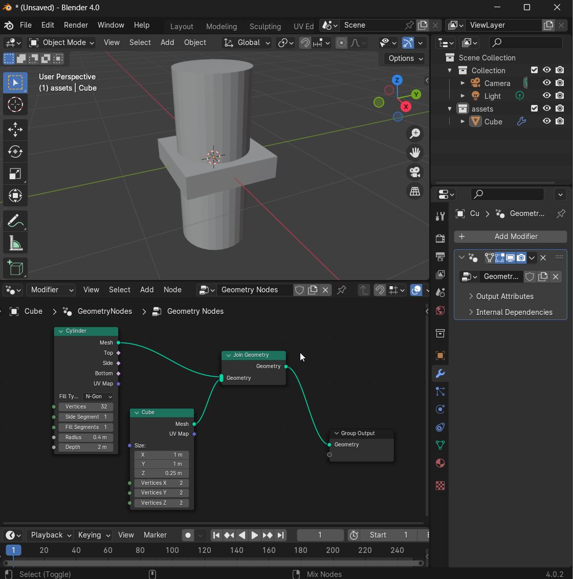
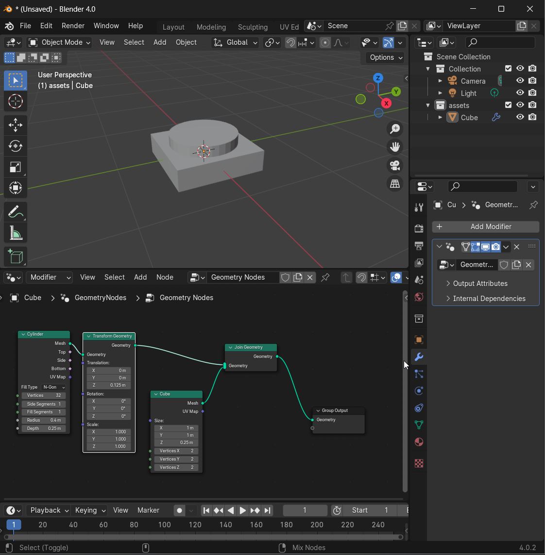
- ...SHIFT+A and add a Transform Geometry node...and connect the mesh output of the Cube geometry node to the geometry input of this node
- ...connect the vector output of the recently added combine XYZ node (with the Z value) and connect it to the translation input of the Transform Geometry node
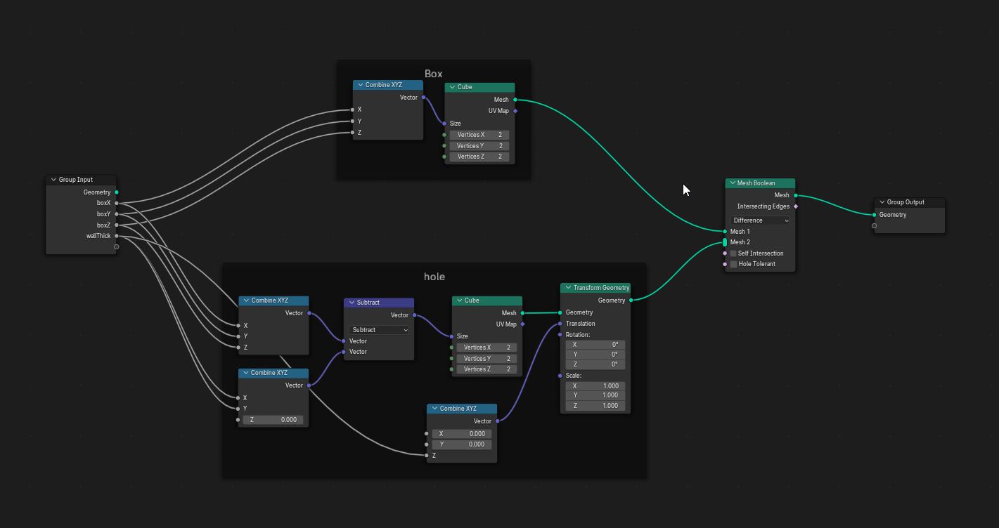
Cutting a hole in the box
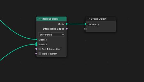
- SHIFT+A and add a Mesh Boolean node
- ...connect the mesh output of the original box cube geometry to the mesh 1 input of the boolean node
- ...connect the geometry output of the Translation Geometry node to mesh 2 of the boolean node
That's it!! The parametric sake cup is done!!
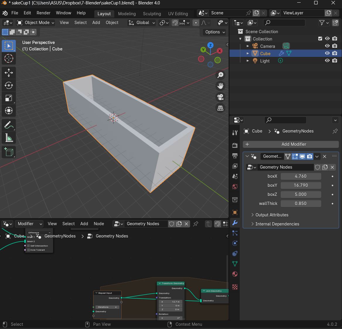
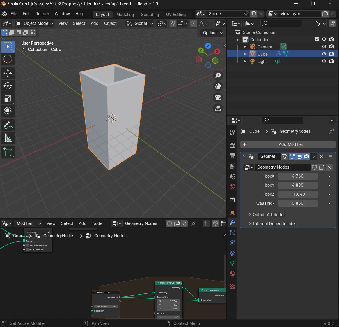
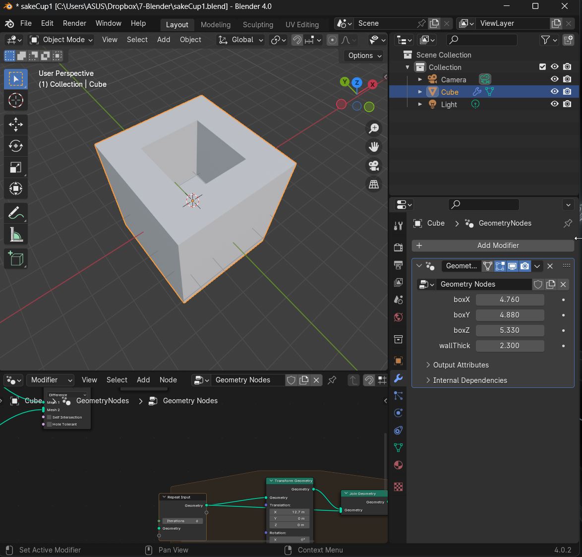
Parameters can be adjusted easily in the parameter list (lower right side)
|
 |
|
 |
|
This is the full node tree for the parametric sake cup.
This is the The Parametric Sake Cup Blender File
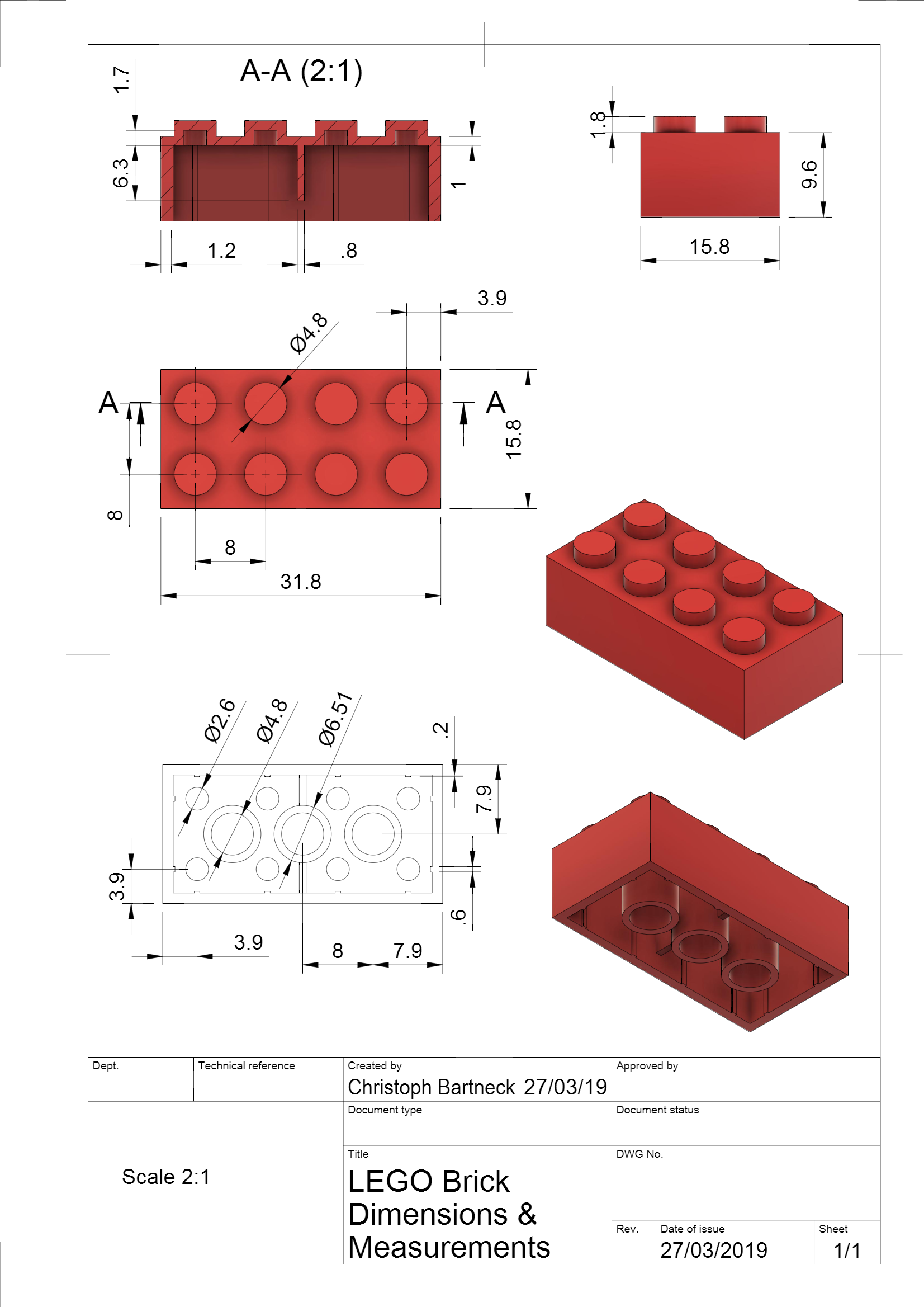
Another "Hello World" Blender Parametric Modeling Tutorial > Lego Brick
Setting Up Blender
- Launch Blender and select the Geometric Node workspace
- In Scene/Units > set Unit System to Metric, Unit Scale to 0.0001, Length to Millimeters
- Edit/Preferences/Add-on...search for and toggle on Node Wrangler add-on
Building the Node Tree > Lego Piece
- Selecting the default cube > create a new Geometry Node tree in the Geometry Node window
- ...SHIFT+A add a "Mesh Cube" geometry
- In the Modeling Window > select and delete the default cube
Modeling the 1x1 Brick Base Unit The strategy...will be to model a 1x1 Lego unit...that can be arrayed into larger Lego bricks by parametrically changing the number of units in the length and width directions.
-In the Geometry Node window > SHIFT+A to add a new mesh/cube and connect it to the output node (to display it in the modeling window)
- ...to the left of the Cube geometry > SHIFT+A to add a Combine XYZ node and connect its output connector to the Cube geometry's size input connector
- ...add Group Input node > create named model parameters here
- ...connect each brick parameter nodes to the XYZ parameters of the cube geometry
- ...a Transform Geometry node is added to move the brick geometry so its bottom does not sit below the XY-workplane
- ...a Math node set to Divide and another CombineXYZ node are added to calculate the amount of Z distance that the brick geometry must be translated upwards.
Modeling the Connector Nub
With the 1x1 brick shape modeled, we move on to model the single cylindrical Connector Nub on top of the brick.
- ...a Cylinder node is added.
- ...2 Transform Geometry nodes, several Math nodes and one Combine XYZ node are added to calculate the distances needed to move the nub above the workplane and to sit on the top surface of the brick.
2 of 3 geometries required to build the parametric Lego brick model are now modeled.
Combine the Base Brick with the Connector Nub - ...add a Mesh Boolean node to combine the Brick and Nub into a single mesh object
Now the 1x1 Brick Base Unit(BBU) has been (mostly) modeled (the hollow at the bottom will be modeled later).
Creating an Array 1x1 Bricks
Now the 1x1 BBU will processed in a Parametric Array that will allow any size larger brick to be created. The procedure involves instancing the Base 1x1 BBU in the X and Y direction...in response to number of X and Y array units desired.
- ...Mesh Line and Combine XYZ nodes are added to receive count values that define the number and offset distance of the instance points in the X and Y directions
- ...Instance on Points nodes are added to array the 1x1 BBU on the instance points previously defined
- ...a Realize Instances node is added to...
- ...a Merge by Distance node is added to combine the array of 1x1 BBU into a single mesh
Move to center the Parametric Brick Array over the Workplane Origin Point
- ...a combination of an Attribute Statistic, Position, Vector Math (Scale), Separate XYZ and Combine XYZ nodes generates the centering distance and direction calculations
- ...a Transform Geometry node is added to move the Brick Array into place centered above the Workplane Origin Point
Modeling a Hollowing Geometry
With the Parametric Brick Array generated and centered over the Workplane Origin Point...as new geometry can be parametrically generated (utilizing the Brick Array dimensions) and used to cut a hollow under the brick.
- ...3 pairs of Math (multiply) and Math (subtract) nodes are added to calculate the XYZ dimensions of the hollow cutting geometry
- ...a Combine XYZ node receives the calculated output and passes a 3D vector to a Cube node.
Use the Hollow Geometry to cut a Hollow from the Brick Array geometry
- ...add a Mesh Boolean (difference) node to cut a hollow into the bottom of the Brick Array with the Hollowing geometry.
Rendering and Outputting the Final Parametric Brick Array
...add a Set Material node to allow for a material to be assigned to the Brick Array geometry.
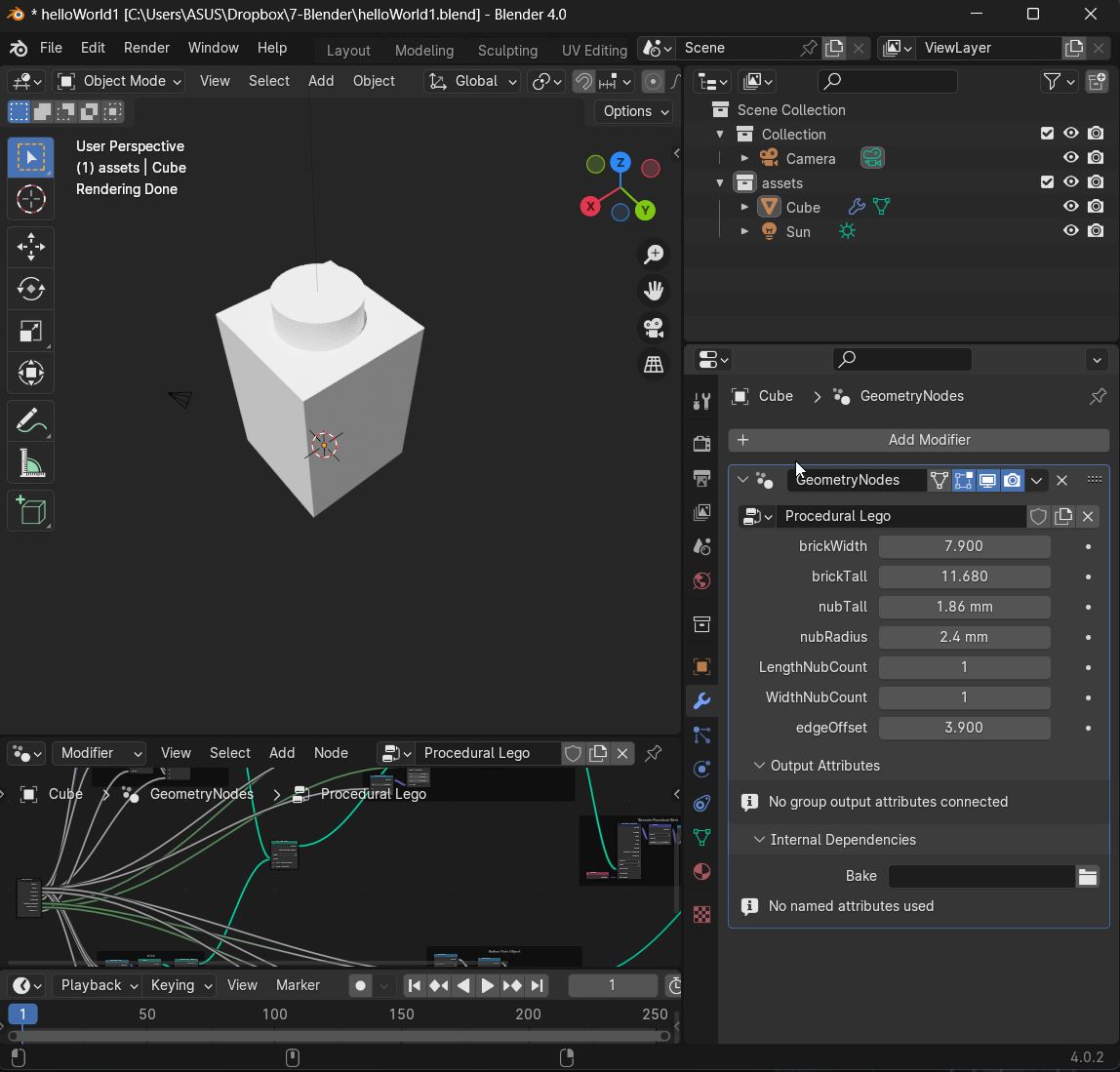
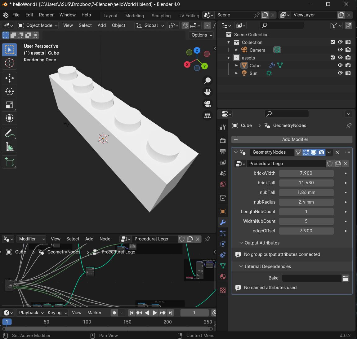
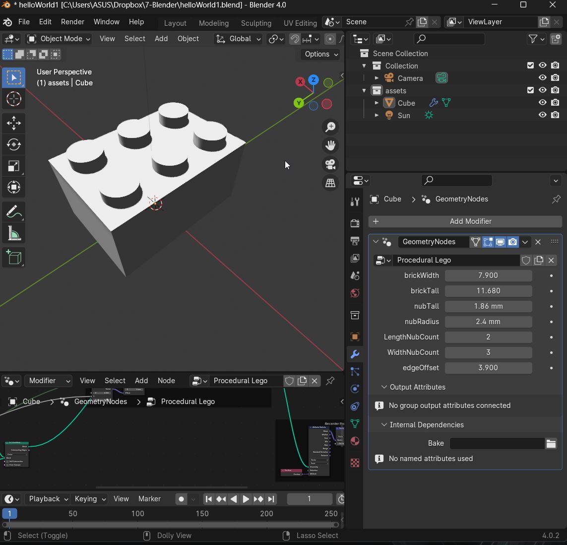
Here are some examples of outputted brick geometries based on different length and width count parameters...
1x1 Brick
1x5 Brick
2x3 Brick
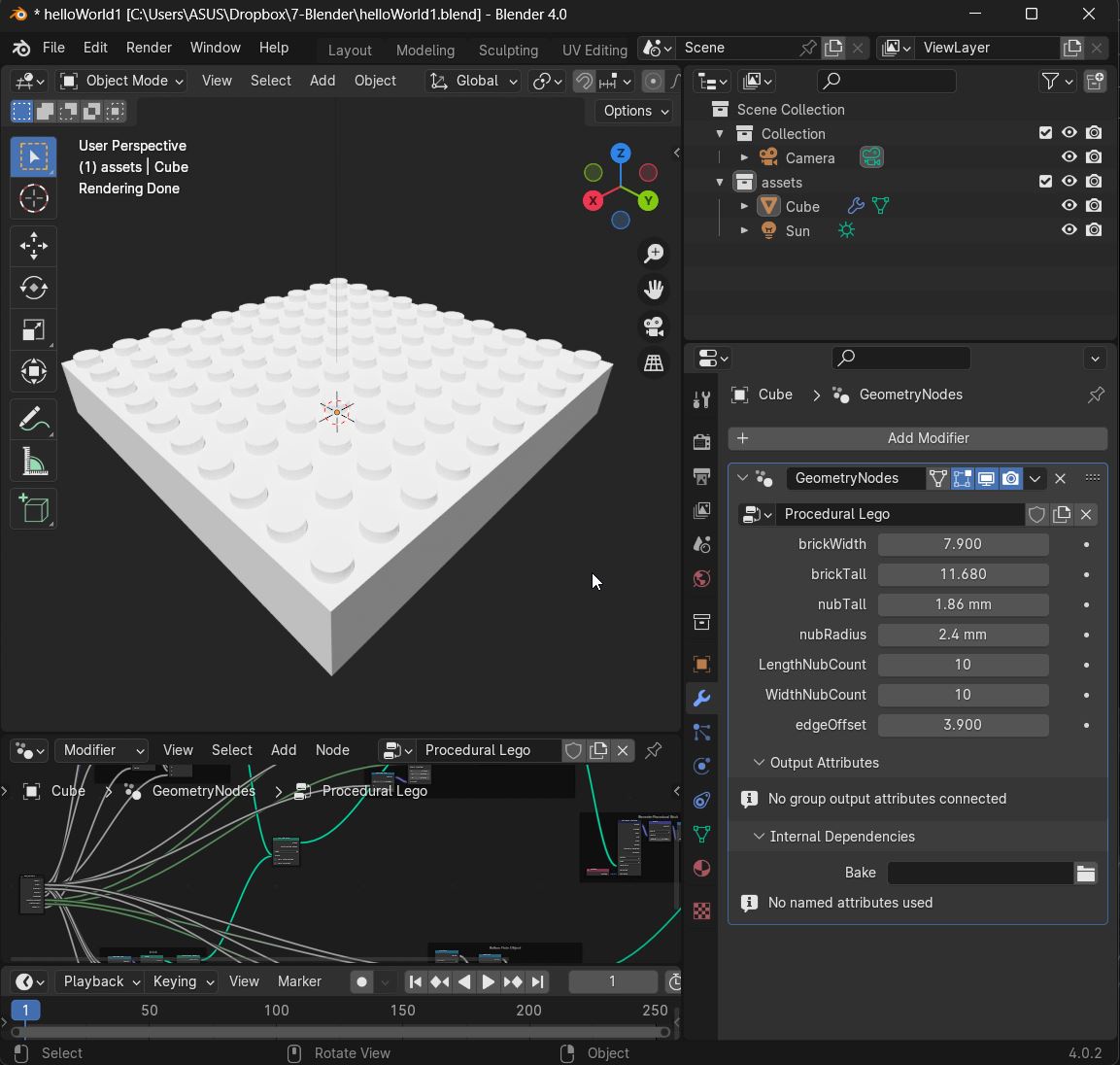
10x10 Brick
The Parametric Lego Node Tree
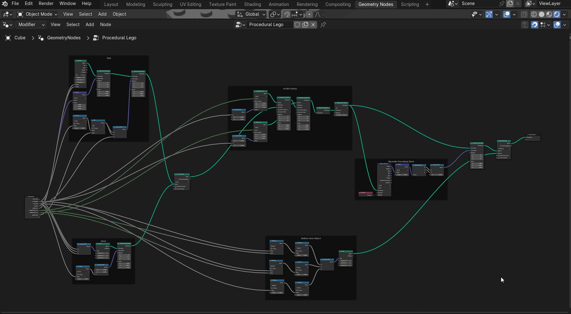
The Parametric Lego Blender File
Exporting .STL files
In order to export the file as an .stl to be printed is NOT needed to apply the modyfiers in the whole scene. This will preserve the object as it is, beeing able to keep changing parameters afer it has been exported. In this way diferent versions of the same object can be saved and printed.
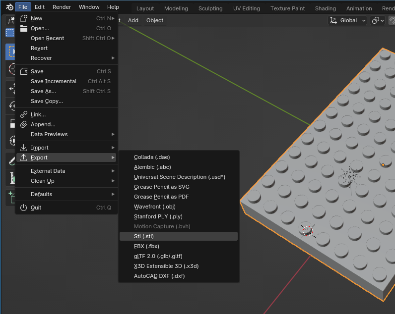
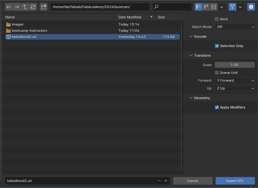
Remember to check Selection Only to export only the objects that we have selected previously, if not the whole scene will be exported. Also confirm Apply Modifyers is also checked to be sure is going to be exported as we see it in the viewport display.
Alternative: Blender Parametric Modeling > Python Scripting
Via the Scripting Workspace.
Every 3D modeling operation command in Blender generates a Python script...which can be cut and paste into another program.
Beginner Python Excercise in Blender: Simple cube location and animation
Alternative: CAD Sketcher
Blender Geometry Nodes does not handle Constaint Solving. CAD Sketcher (free and open source) seems to offer Fusion or FreeCAD like modeling procedures to generate Parametric models.
"CAD Sketcher believes in facilitating precision modeling within blender. We are not looking to replace CAD programs. We just want to bring CAD-like functionality to the world of mesh modeling."
"CAD Sketcher is a constraint-based sketcher addon first developed by hlorus for Blender that allows you to create precise 2d shapes by defining CAD geometric constraints like tangents, dimension, angles, equal and more. These Sketches are then converted into beziers or mesh which stay editable through a fully non-destructive workflow i.e, Geometry nodes and modifiers."**
Download CAD Sketcher add-on as a zip file and the documentation.
s
Installing is fairly straight forward...
- In Blender...Edit/Preferences/Add-ons/Install > select the download zip file
Using CAD Sketcher: Setup
- In Blender's Scene menu set dimensional units...units/units system > metric...units/unit scale > 0.001...units/length > millimeter
- In Blender's Viewport Overlays menu (top right of screen...2 circle icon)...change grid scale to 0.001
- To save dimensional settings for future modeling...File/Defaults/Save Startup File
Using CAD Sketcher: Modeling
Maybe the best way to see how CAD Sketcher works is to see how those with lots of experience with it use it. Here are some video links.
CAD Sketcher vs Precision Modeling
Other Blender References
Blender Procedural Legos
Procedural Modeling with Blender's Geometry Node