4. Computer Controlled Cutting
-
Individual Assignment
- Cut something on the vinyl cutter
- Design, lasercut, and document a parametric construction kit, accounting for the lasercutter kerf which can be assembled in multiple ways
- For extra credit, include elements that aren’t flat
-
Group Assignment:
- Characterize laser cutter’s focus, power, speed, rate, kerf, and joint clearance
About the Laser Cutter
-
Model: Epilog Fusion M2 40 Laser.
-
Selected Features
-
Joystick Controls: Control the laser head with a joystick.
- Color Mapping Settings: Color map different colors to different laser settings.
- Epilog’s print driver for controlling the laser.
Safety Rules
- Always check if the air input and output are open.
- Never cut unknown/not allowed materials materials. More about allowed material.
- Never leave the machine unattended.
- Wait one minute before you open the lid (To allow the toxic gases to leave the machine)
Individual Assignment
Vinyl Cutting
Step 1: Create a model to be vinyl cut. I used Inkscape. I are cutting the image from last weeks’ assignment.
-
The model should be placed [in the lower-left corner. See picture below.
-
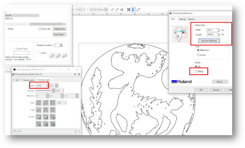
The model should have the following Fill and Stroke properties:
- No fill; Stroke paint: any color
- Stroke style: Dashes: continuous, Width: 0.500 pt
Note
The defined properties are not must. The model in this assignment had those properties.
- Set the document dimensions
Menu File > Document Properties > Width and Height
- Save the document as .svg file
Step 2: Setting up the vinyl cutter
- Turn the machine on.
- Pull lever up.
- Insert the vinyl sheet.
- Align sheet to the edge.
Note
Adjust the pinch rollers by aligning using white markers. There are 3 options:roll/edge/piece, to locate sensor and specify the size of the material for the machine. The options are: - Roll: material as a roll of vinyl film - Edge: the width of the material will measured by the machine - Piece: both the width and length of the sheet will measured by the machine.
- Set the origin of the vinyl cutter or go by default (Left Bottom).
- Pull lever down when satisfied with alignment.
- Pull the lever up when the vinyl is aligned.
-
Console can be used for making selections, For example:
- Up and down arrows to select EDGE, for printing at the edge of the vinyl sheet.
- Other areas of the sheet can be also setup using the other options
- For setting up the Origin, arrows can be used for making adjustments.
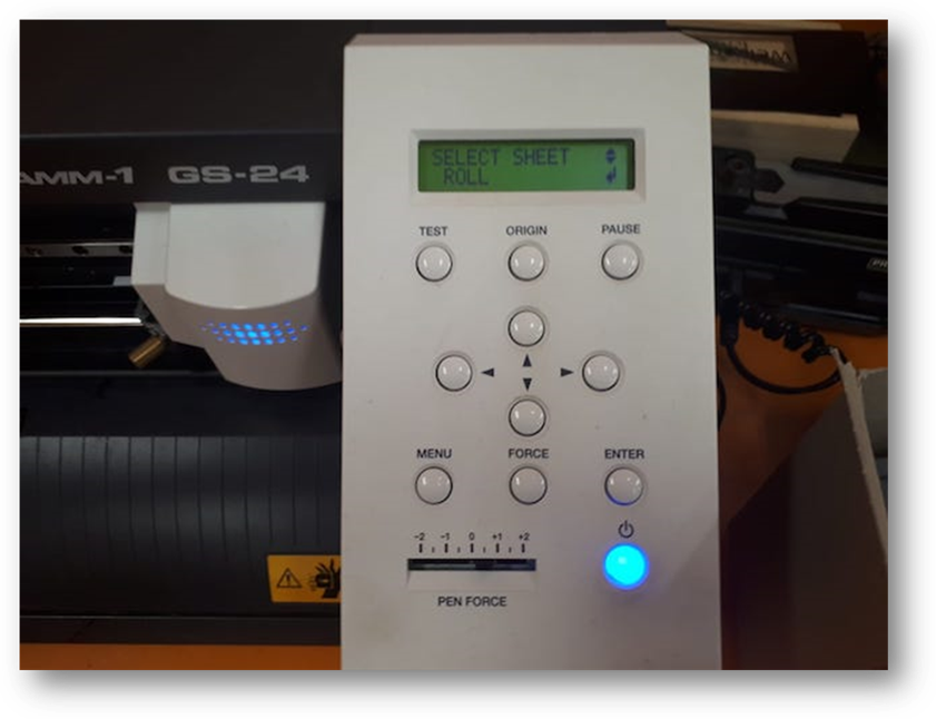
Warning
The image shows ROLL, but the text explains using EDGE. Refer to the previous note for the difference between the two. Even though the image shows ROLL, but EDGE was used.
Step 3: Print the document.
- Select printer: Roland GS-24
- Set the preferences for the cutting area
- Preferences > Size/Cutting Area > Get from Machine
Note
“Get from Machine” will get the size/cutting area using the machine (using the sensor)
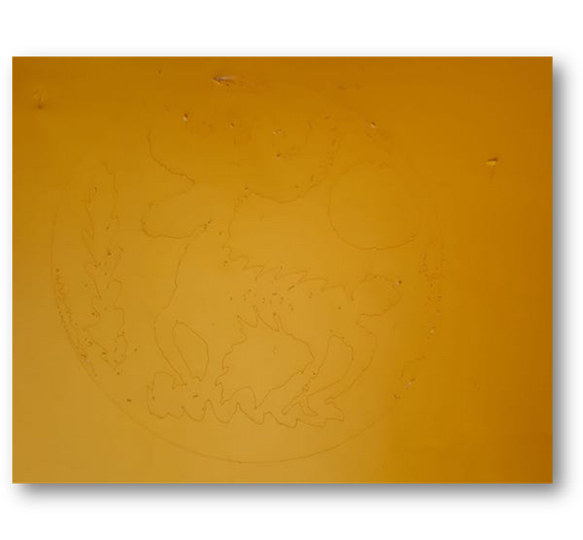
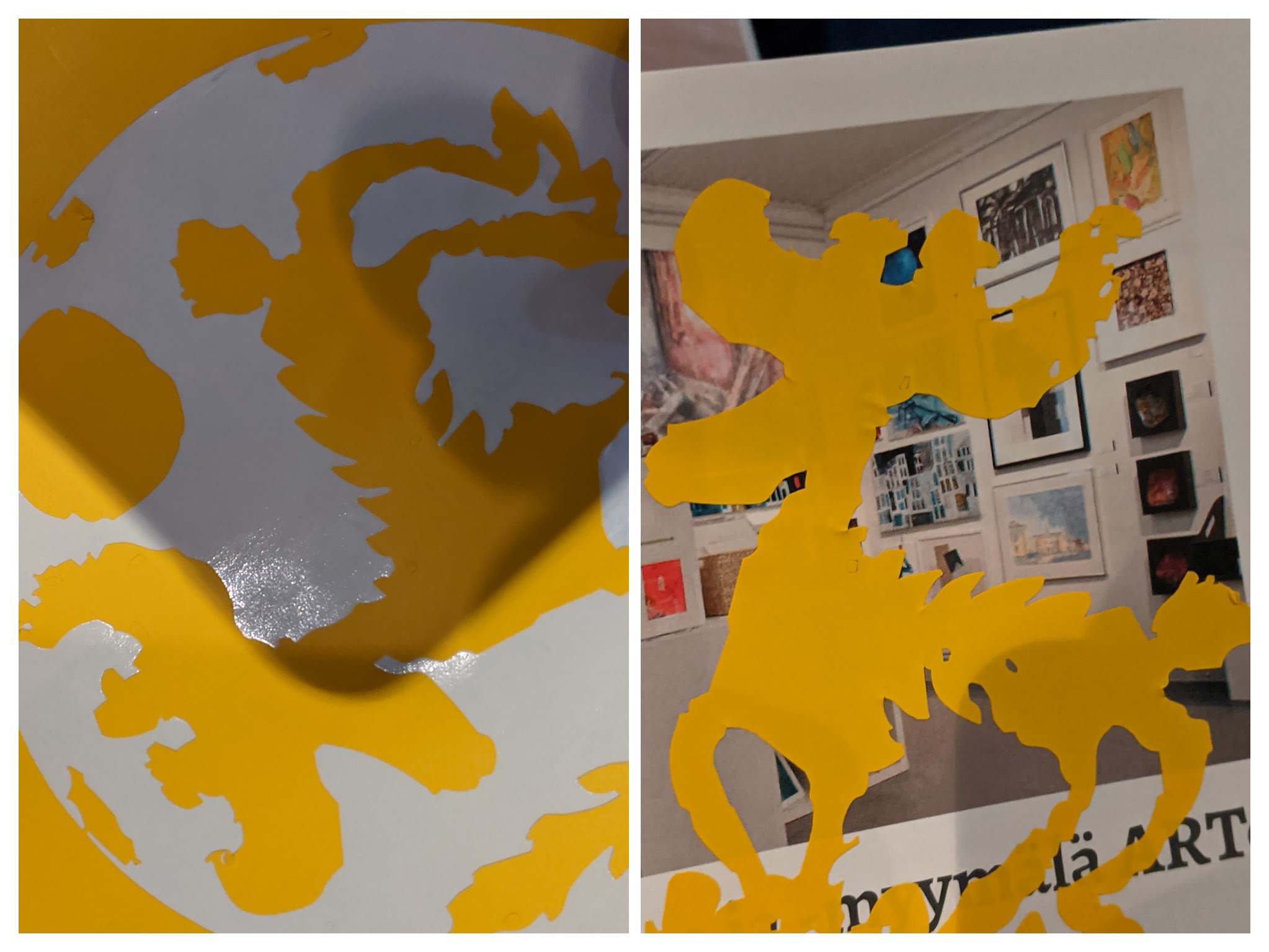
Step 4: Shear and Transfer
- To minimize damaging the model, it is recommended to shear off with tweezers.
- A transfer sheet can be used for transferring the sticker.
Parametric Design
An article about Parametric Design in Blender.
Parametric Construction Kit
For this assignment I went with Blender. However, in order to do parametric design, I used an add-on Sverchok.
“Sverchok IS a parametric tool that relies on easy-to-use visual node-based design to create low-level data structures. Sverchok IS NOT an all-in-one tool. It does not have lighting and the rest of Blender’s toolbox.”
Sverchok’s approach is MATH + MESH + SPLINES + NURBS.
Sverchok has been inspired by Grasshopper from Rhino 3D and it uses a similar node-based visual programming principle.
I followed the documentation to get used to install the plugin and get familiar with the interface: Introduction to NodeView and 3DView and to modular components.
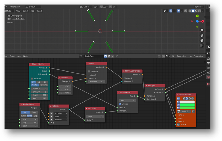
Step 1: A Series of copies of edge or polygon lists.
I needed a series of copies of edge or polygon lists. Usually in conjunction with Matrix Apply, which outputs a series of vertex lists as a result of transform parameters.
Figure 1 shows the nodes used for achieving step 1 Main nodes:
-
List Repeater: Allows explicit repeat of lists and elements. The node is data type agnostic, meaning it makes no assumptions about the data you feed it.
-
Plane MK2 was copied. Plane MK2 is a Plane generator creates a grid in the plane XY/YZ or ZX, based on the number of vertices and the length between them in X and Y directions.
-
Range Integer was used for generating sequences of Integer values.
Other nodes in Figure 1 can be found in documentation under nodes
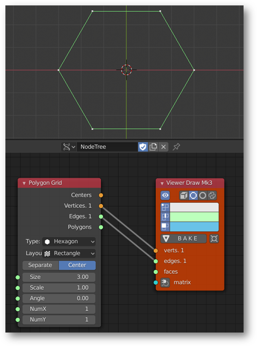
Step 2: Creating a Polygon.
This was done using Polygonal Grid
Image 2 shows creating the Polygon and displaying it using Viewer Draw MKII
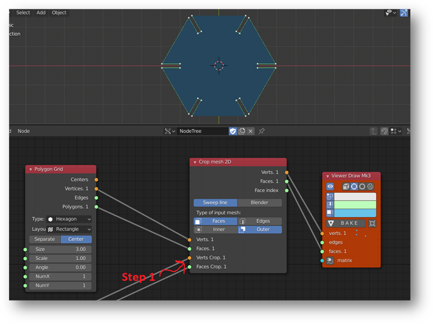
Step 3: Cropping Step 1 out of Step 2!
- Crop mesh 2D node was used for that purpose.
The node takes two meshes determined by faces find them intersection and dependently of mode show either overlapping each other faces or faces of first mesh which has not overlapping.
Image 3 shows how Crop mesh 2D node was introduced
Step 4: Adding a parameter for replicating the product.
A Plane MK2 and Matrix in were used for that purpose.
Image 4 shows the final product before baking it!
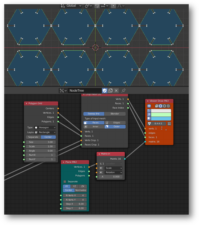
Note
To account for kerf, the the “Verts and Face Crop” value fed into Crop Mesh 2D can be edited. To learn more about the parameters, see the documentation for each of the modules used under Blender documentation.
Exporting from Blender to Inkscape
Freestyle SVG Exporter add-on was used to achieve this task.
In Blender, the add-on can be enabled via:
Preferences ‣ Add-ons ‣ Render ‣ Freestyle SVG Exporter
The GUI for the exporter can be seen under the render tab of the Properties editor. Options for editing the preferences of the plugin can also be seen there.
Exporting the .svg is done automatically when rendering. More about Rendering in Blender.
Note: Objects need to be visible in Camera View.
The exported .svg file is written to the default output path
Properties ‣ Output ‣ Output
Video 1 shows exporting .svg file in Blender
Editing .svg file in Inkscape for Laser Cutting
Few things need to be modified: Dimensions and Stroke fill
Video 2 shows stroke edits done in Inkskape for preparing the file for laser cutting.
Video 3 shows demonstration for parametric modeling; nodes’ sliders for modifying design
Laser Cutting
Group Assignment
Laser Cutting Procedure
-
Jogging
-
Jog >> Set the start point
* Select “Jog” on the panel and use the joystick to adjust the start point. When reaching the ideal location, press down the joystick so the machine will set that location as the start point.
-
Focusing
-
A Triangle-shaped focus calibrator to is used to adjust the focus.
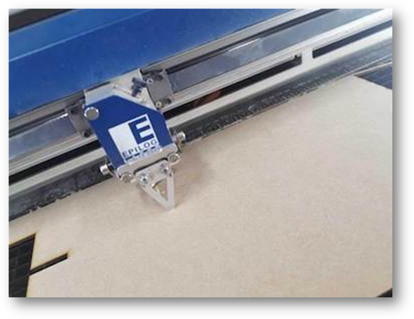
* Focus >> Adjust with Focus Calibrator
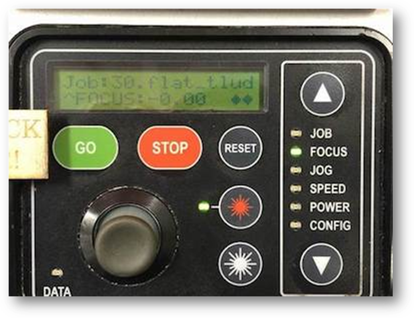
* Select “Focus” on the panel and press the joystick while pushing it upward or downward to adjust the distance between the material and the focus lens.
Stop when the calibrator just touches the material surface and press the joystick again to set the height of focus. After calibrating, take out the calibrator. This machine is also possible to be automatically adjusted.
-
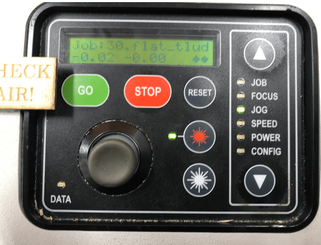
Selecting a Job
-
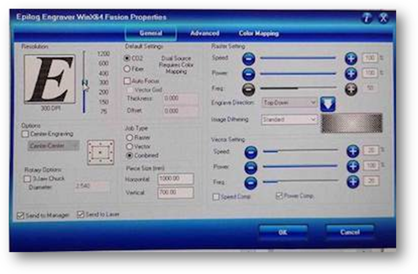
A PDF document should be used for laser cutting at the Fab Lab of Oulu. There are several properties that one can adjust according to the materials to be used and the purpose of the laser cutting job. Press “Print” or “Ctrl +P” will evoke this setting menu.
-
Depending on the material (which is 3mm MDF in this case) and the purpose (engrave, cutting, or combined), one can load different preset configuration files.
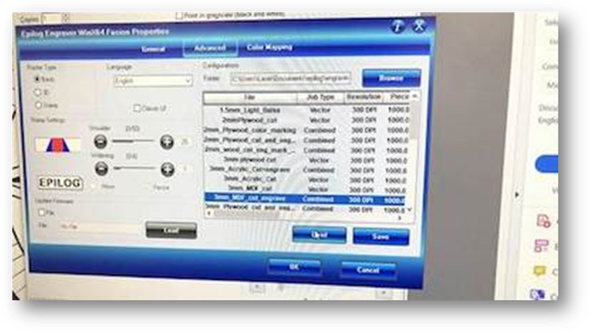
* Engraving will create pixel-based patterns while cutting will cut through the material.
Note
In Fab Lab Oulu, we consider the line width of 0.02 mm for cutting through and for engraving the line width should be thick enough for example 0.05, 0.1 mm and etc.
-
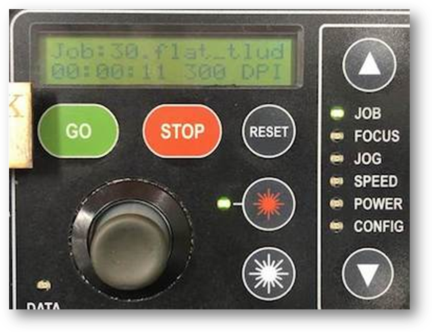
Job >> Select files
-
After sending the work to be printed to the laser cutter, select “Job” on the panel and use the joystick to select the file. Press “Go” when it is ready.
Speed, Power and Frequency
The important things of cutting and engraving are to set up the power, speed, and frequency. The power and speed laser parameters are the most important settings in the material database. They can be set as a percentage between 0 and 100%.
The power describes the output power of the laser. 0% is the minimum power and 100% is maximum power. We can set up the power from 0% to 100% according to different materials. For dark wood engravings or stamp engravings, we generally need high power, whereas low values are used for materials such as paper.
The speed describes the movement of the laser head. Fast speeds lead to short exposure times, slow speeds lead to long exposure times. For example, large-scale engravings materials are engraved at high speeds between 80 and 100%, but for photo-engravings with lots of detail on wood, the speed should not exceed 10%. This setting also affects the quality of the laser cut.
The frequency is decisive and is given in Hz (=Hertz). It specifies the number of laser pulses per second. For a laser, the value can be set within a range of 1,000 to 60,000 Hz. For example, if we want to achieve a smooth edge when cutting acrylic, we need higher temperatures and thus this value is set to at least 5,000 to 20,000 Hz. On the other hand, when cutting wood, a low frequency of 1000 Hz is necessary in order to achieve, for example, the brightest possible cutting edge.
Raster and vector are different graphic file types that require different modes of laser processing. The difference between vector and raster graphics is that raster graphics are composed of pixels, while vector graphics are composed of paths or lines. The main differences between modes required to laser process each type involve the movement of the axles and in the parameters used.
A: Vector engraving is often referred to as “scoring.” The file to be printed is a graphics file consisting of vectors (lines and curves of a geometry), marked as hairlines in the graphics. When the file is imported from the graphics program, the outline is identified as vector engraving. Vector by vector is traced by the laser and then engraved.
In vector engraving, the axles move simultaneously, and more slowly than in raster engraving. The process itself is the same as in laser cutting; the difference is the selected power setting. If a low power setting is chosen, the line is “scored” as engraving; higher power produces a vector cut.
We tested it by setting up different speed, powder, and frequency. It is clear, that when we set up the power=100, frequency=20, speed between 20-10, it is easier to cut the wood material also the speed= 20, frequency=20 and power=100.
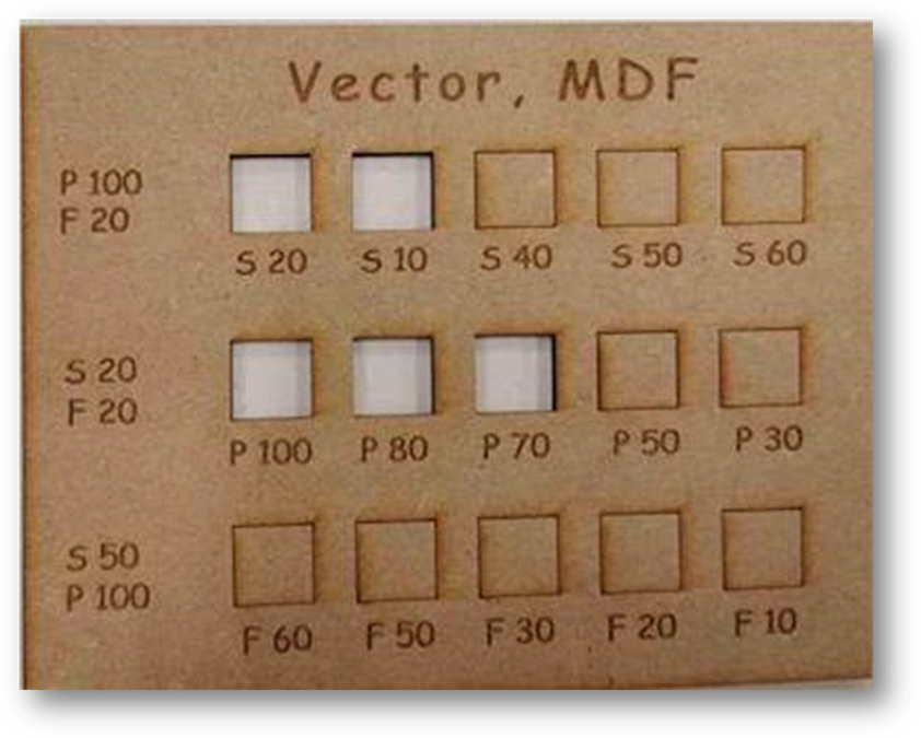
And, by the slightly pressing, there are two pieces of these that can be removed.
Raster Engraving
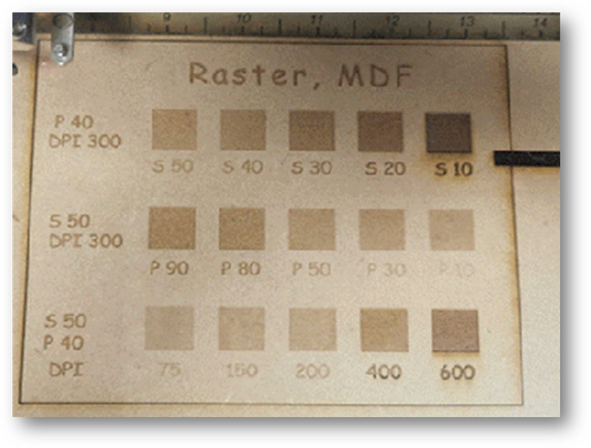
A raster file is a bitmap, which means it is made up of pixels. The image is engraved by the laser machine line by line, point by point, similar to the way in which an inkjet printer applies the ink, but instead of ink is applied, the material is removed pixel by pixel by the laser. This is a “bi-directional” process in which engraving is done in an alternating fashion in both directions.
In raster engraving, the DPI parameter is important because it controls the density of the laser points.
-
In the first line, we set up the DPI=300, Power=40, and the speed from 50 to 10.
-
In the second line, we set up the DPI=300, speed=50, and the power from 90 to 10.
-
In the third line, we set up the power=40, speed=50, and the DPI from 75 to 600.
we can see the difference and choose the more suitable setting up for our assignments.
Focus adjustment
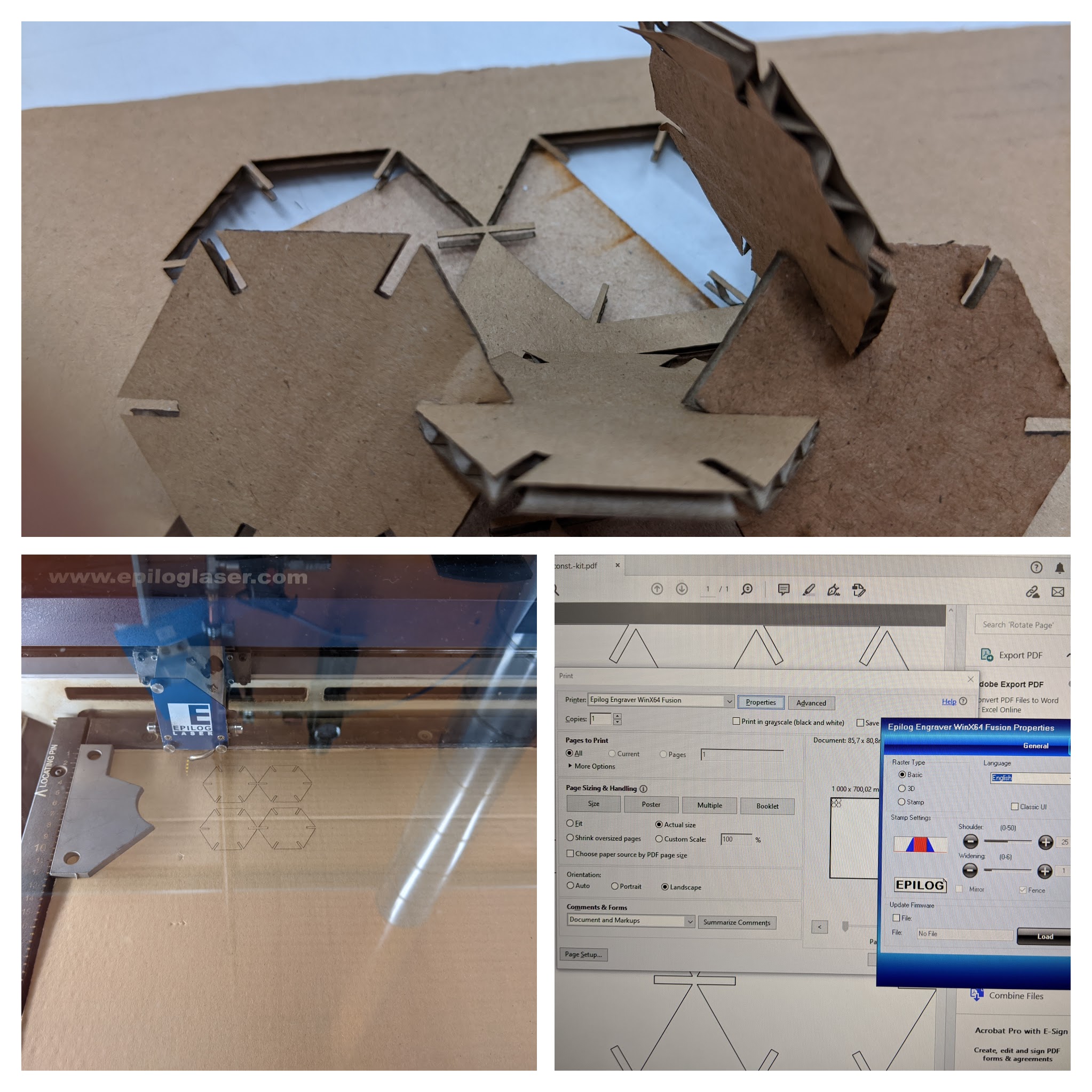
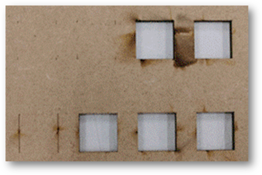
As discussed above, the focus of a laser cutter can be adjusted manually or automatically. Setting an inaccurate focus for a laser cutting task can cause problems.
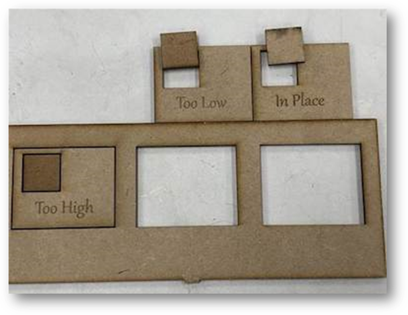
As shown in the image, the parts are detached because they have the line width of 0.02 mm and they were supposed to be cut through, which was not the result of the low focus. However, low focus has affected the engraving result.
Also, as you can see from the image, ‘too low focus’ is different for example, it has resulted in a lighter engraving compared to the ‘too high focus’. In the original file, the color of the square in set black (RGBA:0,0,0,255), so normally it should result in a darker engraving than what came out after lowering the focus. The picture of the piece with ‘focus in place’ is showing the wrong side and unfortunately the engraved area is on the other side of the piece, otherwise you could compared the engraving result of focused and de-focused laser!
Kerf Calculation
As the laser beam, which has an inherent size, cuts through the material, it burns away additional material. Such a gap between the designed width and actual laser cut width is known as “kerf”. Kerf is determined by the laser beam size as well as material properties and thickness. In the image below, kerf is yellow + blue Or the blue part itself which is the laser beam size. If yes, please modify the picture.
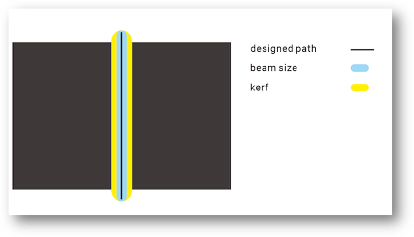
Kerf is an important parameter to be considered during laser cutting design. In short, how we deal with kerf should be “inside in, outside out”.
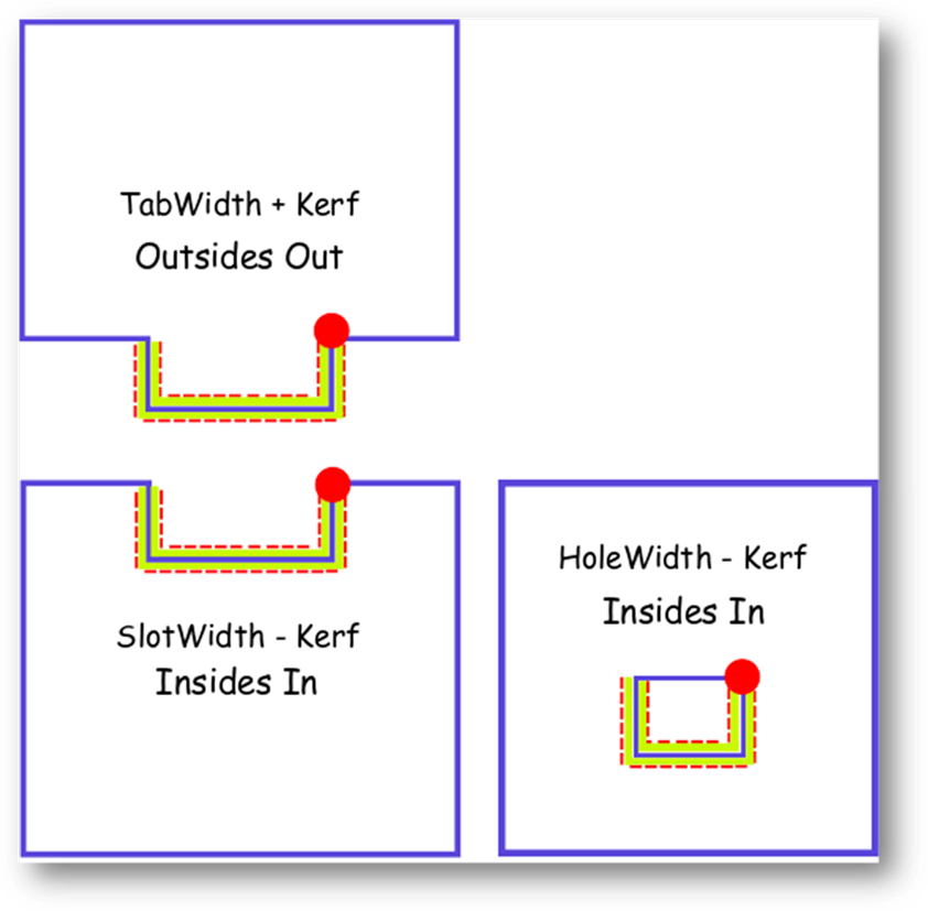
(credits: our instructor Behnaz Norouzi)
For the inside part like slot and hole, the actual width will be wider than the designed number, so we need to subtract the kerf. On the other hand, for the outside part like a tab, its actual width will be thinner than it has been designed, so we need to add the kerf width to it.
Kerf test
As the laser beam, which has an inherent size, cuts through the material, it burns away additional material. Such a gap between the designed width and actual laser cut width is known as “kerf”. Kerf value is very sensitive and depends on a whole set of parameters: starting with laser basic settings as focal point diameter, power, speed and rate, then material parameters as physical properties and thickness. There are some average values available for different materials. It’s important to take account of the kerf in the design, to get the actual cut width.
Kerf is an important parameter to be considered during laser cutting design. In short, how we deal with kerf should be “inside in, outside out”.
Kerf definition looks quite confusing in the beginning, but in the end the simple rule should be applied when we design parts to be connected:
-
For outer parts like a tab “design parameter_x + kerf”.
-
For inner parts like slots and holes “design parameter_x * kerf”.
Ladder (combined & test)
Our instructor Behnaz for this week was super assistive, under her supervision we started the first test to define the kerf for MDF 3mm material and 3mm Acrylic.
A drawing was made in Inkscape to cut 20 pieces of 5 mm width, 100 mm total length for MDF 3mm and Acrylic 3mm materials. Image below shows measuring Actual length after cutting for Acrylic 3 mm.
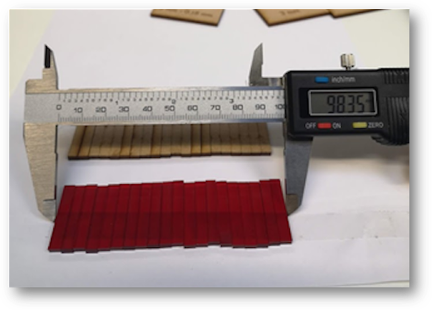
Sticking 20 pieces with double-side tape was super helpful to keep pieces together. It turned out that micrometer measurements are also very sensitive to the position and to the person making the measurement :) Well, nothing is perfect! For the MDF total length was 98.5 mm, while for the Acrylic we got 98.35 mm.
Knowing these parameters, we retrieved the kerf by simple formula:
- (Total length of original drawing – Actual length after cutting)/20
- MDF 3mm (S=20, P=100, F=20): (100 mm – 98.5 mm)/20 = 0.07 mm
- Acrylic 3 mm (S=12, P=100, F=100): (100 mm – 98.35 mm)/20 = 0.08 mm
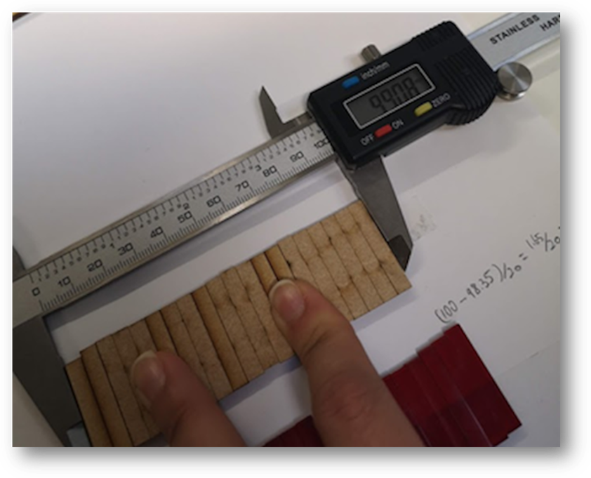
Image below shows the proper way to use micrometer! However, in this way kerf value was even smaller 0.05 mm]
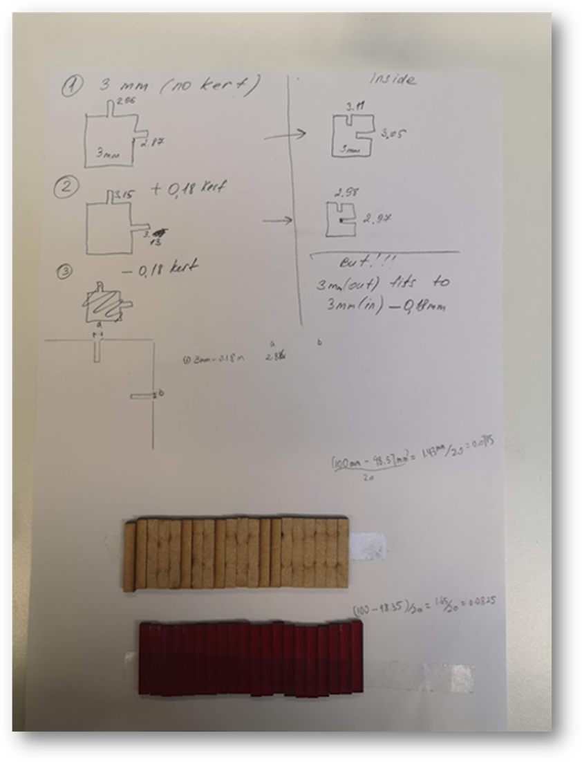
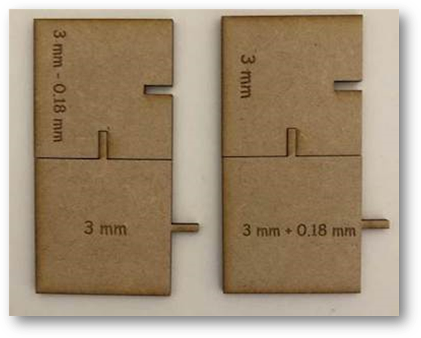
Values look fine, but still a bit low for the kerf used before in Fablab, which was 0.18 mm. Yet we didn’t give up and another test was ahead. We got 4 MDF 3mm pieces with slots and tabs:
We have two types of inside pieces (3-0.18mm/3mm) and two types of outside pieces (3mm/3+0.18mm).
- TABS NO KERF (3mm) – vertical tab = 2.96 mm, horizontal tab = 2.87.
- SLOTS NO KERF (3mm) – vertical tab = 3.11 mm, horizontal tab = 3.05.
- TABS + KERF 0.18 (3+0.18mm)– vertical tab = 3.15 mm, horizontal tab = 3.13.
- SLOTS - KERF 0.18 (3-0.18mm) – vertical tab = 2.98 mm, horizontal tab = 2.97.
According to the measurements of the actual parameters, if we try to connect 1 and 2 pieces 3 mm (NO kerf), the connection will be loose, as tabs width is smaller than 3 mm, while the actual width of slots is bigger than 3 mm.
As a result, due to the joint clearance, the [3-0.18mm & 3mm] combo and [3mm & 3+0.18] combo fit great with each other. On the other hand, [3mm & 3mm] combo was too loose, while [3-0.18mm & 3+0.18] combo cannot fit each other.
Another observation to note is that the direction of the cut may influence the size, as observed here for the difference between horizontal and vertical geometries. Image below Summarizes sketch made during group work!
In the end, to make the design work properly after cutting, it is necessary to consider the kerf, and wouldn’t be the bad idea to check some small parts for the proper adjustment before cutting the whole drawing.
Joint Clearance
The joint clearance refers to the distance between surfaces of a joint, which should be considered in the parametric design as well. For example, in order to make the parts fit well, the tab and the slot should not be designed with the exact width.
In the laser cutting cases, because the kerf partially takes the role of joint clearance, it is not so critical to include this parameter. However, in other cases, a joint clearance should be manually added to one of the inside and outside parts to make them fit well.
 !
!
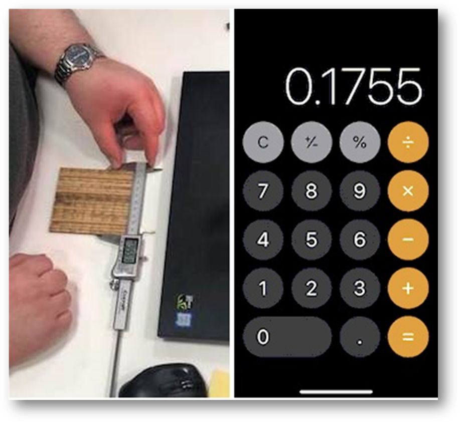
During group work, we did an experiment to test the joint clearance. We again used the ladder test, during which we measured the thickness of 20 MDF sticks and calculated the individual kerf by dividing the number by 20, which gives us the number of 0.1755.
Summary
As a conclusion, our laser cutter’s focus can be set manually with the calibrator or automatically with the computer wired to it. The power, speed, rate(frequency) can be set from 0% to 100%. The joint clearance we used was from the experiment, which is 0.18mm (0.1755mm).
Resource Files
Group Work
Individual