9. Embedded Programming
-
Individual Assignment
- Read a micro-controller data sheet
- Program your board to do something
- with as many different programming languages
- with as many different programming environments as possible
-
Group Assignment
- Compare the performance and development workflows for other architectures
Individual Assignment
Useful links
- ATtiny212/412 micro-controllers datasheet
- Arduino With Python
- Arduino IDE
- Python in VS Code
- What Is Pip?
- pyFirmata
Datasheet Reading
ATtiny212/412 micro-controllers datasheet was chosen. ATTINTY412 is a 8-bit AVR® Reduced Instruction Set Computing (RISC) architecture microcontroller.
Features of the ATtiny212/412 micro-controllers are shown below:
- AVR 8-bit CPU
- Running at up to 20MHz
- Single Cycle I/O Access
- Two-level Interrupt Controller
- Two-cycle Hardware Multiplier
- 2/4KB In-system self-programmable Flash Memor
- 64/128B EEPROM
- 128/256B SRAM
- Power-on Reset (POR)
- Brown-out Detection (BOD)
- Clock Options
- Single Pin Unified Program Debug Interface (UPDI)
- Three Sleep Modes
- 6-channel Event System
- Multiple Timers/Counters
- Master/Slave Serial Peripheral Interface (SPI)
- Master/Slave TWI with Dual Address Match
- Three Sleep Modes
- Configurable Custom Logic (CCL) with Two Programmable Lookup Tables (LUT)
- Analog Comparator (AC) with Low Propagation Delay
- 10-bit 115ksps Analog to Digital Converter (ADC)
- 8-bit Digital to Analog Converter (DAC)
- Five Selectable Internal Voltage References – Automated CRC Memory Scan
- Watchdog Timer (WDT)
- External Interrupt
- 6 Programmable I/O Lines
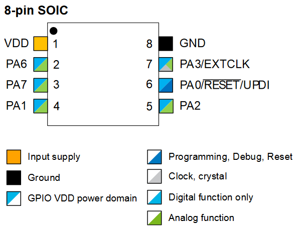
- 8-pin SOIC150
- -40°C to 105°C–
- -40°C to 125°C
- 0-5MHz @ 1.8V – 5.5V
- 0-10MHz @ 2.7V – 5.5V
- 0-20MHz @ 4.5V – 5.5V
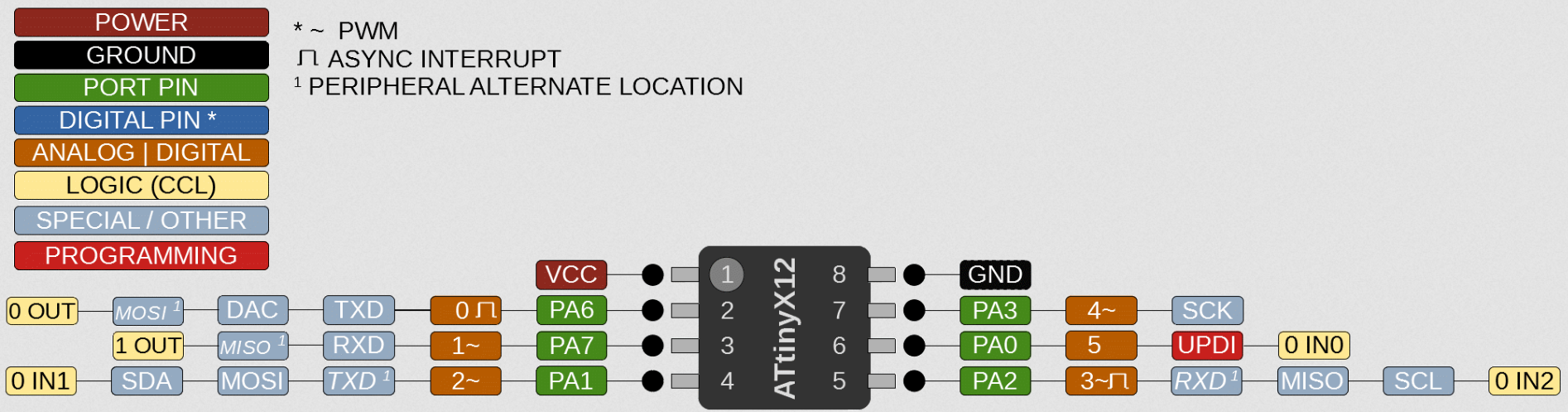
Protocol: UPDI
Programming and debugging is done using the Unified Program and Debug Interface (UPDI), which is a Universal Synchronous and Asynchronous Receiver-Transmitter (UART) based interface using the RESET pin for data reception/transmission.
Clocking of UPDI is done by an internal oscillator. (see p. 379, ATtiny212/412 micro-controllers datasheet.
Communication through the UPDI is based on standard UART serial communication.
Communication for UART:
- Receiver - RX (PA1)
- the Transmitter TX (PA2).
UPDI can access the entire I/O and data space of the device
In the designed echo-board, LED is connected to PA7, which is in ATtiny412 is pin number 3 and the BUTTON to PA6, which is pin number 2.
Below are the pin numbers of the ATtiny412
Board Programing
A electronic board (programmer) was produced (see Electronics Production). An electronic board (programmable) was also designed with the ATtiny412 micro-controller (see Electronics Design).
Note
Pin-out: 8-pin SOIC, Pin numbers and schematic can be used to define pins in code.
Schematic of the board
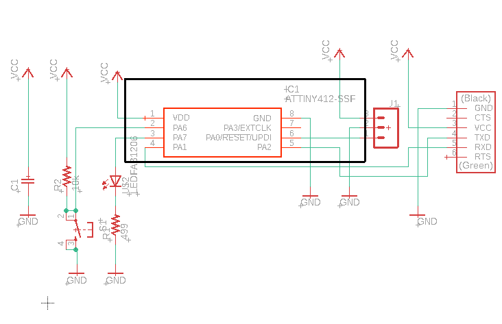
Therefore, LED pin number is 1 and the BUTTON pin is 0.
“Blink + Button” With Arduino IDE
A tutorial showing how to set up an Arduino board as the UPDI Programmer and the process of setting up the megaTinyCore on your Arduino IDE can be found here.
In short, to configure the board, more libraries are needed.
First, add the library
File > Preference > Additional Board Manager URLs
http://drazzy.com/package_drazzy.com_index.json
Then add the board:
tools > Boards > Boards Manager
Then install the megaTinyCore and megaAVR boards packages.
Programming the application board using the programmer board
Uploading the Blink Example Sketch
const int ButtonPin = 0;     // pushbutton pin
const int LedPin =  1;      // LED pin

int ButtonState = 0;         // variable for button status
int PreviousButtonState = 0;

void setup()
{
  // initialize LED pin as output:
  pinMode(LedPin, OUTPUT);
  // initialize the Pushbutton pin as input:
  pinMode(ButtonPin, INPUT);
}

void loop() {
  // read the state of the pushbutton value:
  ButtonState = digitalRead(ButtonPin);
  // check if the pushbutton is pressed. If it is, the ButtonState is HIGH:
  if (ButtonState != PreviousButtonState)
  {
    if (ButtonState == HIGH){
      digitalWrite(LedPin, HIGH);
    }
    else
    {
      digitalWrite(LedPin, LOW);
    }
  }
  PreviousButtonState = ButtonState;
}
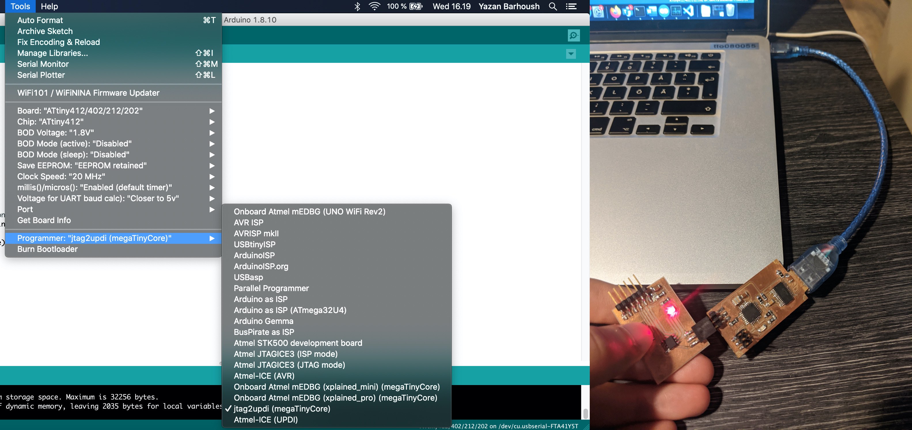
Under Tool on Arduino IDE, make sure that:
- Board: ATtiny412/402/212/202
- Programmer: jtag2updi(megaTinyCore)
Video
Board Blink when Button is pressed!
“Hello, World!” With Arduino and Python in VScode
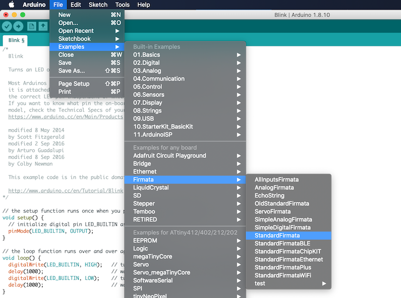
Before writing a Python program to board, the Firmata sketch is needed to be uploaded. So that, the protocol can be used to control the board.
The sketch can be found in the Arduino IDE’s built-in examples under:
File menu > Examples > Firmata > StandardFirmata
The figure below shows finding StandardFirmata sketch
To work with the Firmata protocol in Python, the pyFirmata package is needed. It can be installed with pip:
pip install pyfirmata
Below is shell showing the installation of pip (if needed) and then pyfirmata.
Note
pip was installed on this machine already, that is why all the packages found existing and all requirements are satisfied already. See Useful Links for more help.
% curl https://bootstrap.pypa.io/get-pip.py -o get-pip.py
  % Total    % Received % Xferd  Average Speed   Time    Time     Time  Current
                                 Dload  Upload   Total   Spent    Left  Speed
100 1825k  100 1825k    0     0  2740k      0 --:--:-- --:--:-- --:--:-- 2736k
% python3 get-pip.py
Collecting pip
  Using cached pip-20.1.1-py2.py3-none-any.whl (1.5 MB)
Installing collected packages: pip
  Attempting uninstall: pip
    Found existing installation: pip 20.1.1
    Uninstalling pip-20.1.1:
      Successfully uninstalled pip-20.1.1
  WARNING: The scripts pip, pip3 and pip3.7 are installed in '/Library/Frameworks/Python.framework/Versions/3.7/bin' which is not on PATH.
  Consider adding this directory to PATH or, if you prefer to suppress this warning, use --no-warn-script-location.
  NOTE: The current PATH contains path(s) starting with `~`, which may not be expanded by all applications.
Successfully installed pip-20.1.1
% export PATH=$PATH:/Library/Frameworks/Python.framework/Versions/3.7/bin
% echo $PATH
/usr/local/bin:/usr/bin:/bin:/usr/sbin:/sbin:/usr/local/share/dotnet:~/.dotnet/tools:/Library/Apple/usr/bin:/Library/Frameworks/Mono.framework/Versions/Current/Commands:/Library/Frameworks/Python.framework/Versions/3.7/bin
% pip install pyfirmata
Requirement already satisfied: pyfirmata in /Library/Frameworks/Python.framework/Versions/3.7/lib/python3.7/site-packages (1.1.0)
Requirement already satisfied: pyserial in /Library/Frameworks/Python.framework/Versions/3.7/lib/python3.7/site-packages (from pyfirmata) (3.4)
After the installation is complete, the equivalent Blink application using Python and Firmata can be run in VScode, by pressing the run button:
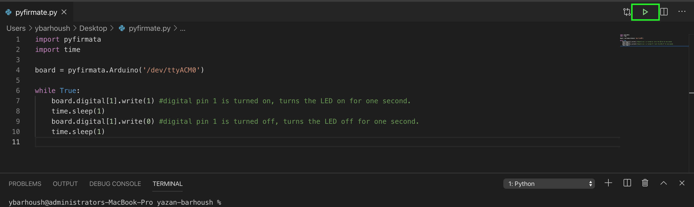
import pyfirmata
import time

board = pyfirmata.Arduino('/dev/ttyACM0')

while True:
    board.digital[1].write(1) #digital pin 1 is turned on, turns the LED on for one second.
    time.sleep(1)
    board.digital[1].write(0) #digital pin 1 is turned off, turns the LED off for one second.
    time.sleep(1)
The code can be explained as the following:
- Import pyfirmata and use it to establish a serial connection with the Arduino board.
- Configure the port in this line by passing an argument to pyfirmata.Arduino().
- board.digital is a list whose elements represent the digital pins of the Arduino.
- methods read() and write(), which will read and write the state of the pins.
Note
Use the Arduino IDE to find the port and upload the blink code.
Warning
“Hello, World!” With Arduino and Python in VScode has not been test with the board due to time limitations.
Group Work
https://fabacademy.org/2020/labs/oulu/students/tatiana-avsievich/8week.html