14. Networking and Communications
Individual Assignment
-
Individual Assignment
- Design, build, and connect wired or wireless node(s) with network or bus addresses,
-
Group Assignment
- Send a message between two projects
Network Design 01
Useful Links
Connection
The network topology is shown below. An Arduino Uno board was connected to board that was designed previously (See board from Electronic Design)
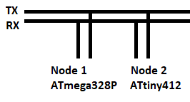
The table below shows where the pins where connected.
| Def. | ATTiny412 | Arduino Uno |
|---|---|---|
| TX | Pin 3 | Pin 4 |
| RX | Pin 4 | Pin 5 |
The figure below shows where the pins where connected.
Code
See SoftwareSerial: available() for code documentation.
Arduino Uno Code
#include <SoftwareSerial.h >
SoftwareSerial mySerial(0, 1);

const char node = '1';
const int ledPin = 13;
int incoming;

void setup()
{
  mySerial.begin(9600);
  pinMode(1, INPUT);
  pinMode(ledPin, OUTPUT);
}

void loop()
{
  if (mySerial.available() > 0)
  {
    digitalWrite(ledPin, HIGH);
    delay(300);
    digitalWrite(ledPin, LOW);
    delay(300);

    incoming = mySerial.read();

    if (incoming == node)
    {
      digitalWrite(ledPin, HIGH);
      pinMode(1, OUTPUT);
      mySerial.print("node ");
      mySerial.println(node);
      pinMode(1, INPUT);
      delay(300);
      digitalWrite(ledPin, LOW);
    }
  }
}
ATTiny412 Board Code
#include <SoftwareSerial.h>
SoftwareSerial mySerial(2,3);

const char node = '2';
const int ledPin = 1;

int incoming;
void setup()
{
  mySerial.begin(9600);
  pinMode(ledPin, OUTPUT);
  pinMode(3, INPUT);
}

void loop()
{
  if (mySerial.available() > 0)
  {
    digitalWrite(ledPin, HIGH);
    delay(300);
    digitalWrite(ledPin, LOW);
    delay(300);

    incoming = mySerial.read();

    if (incoming == node)
    {
      digitalWrite(ledPin, HIGH);
      pinMode(3, OUTPUT);
      mySerial.print("node ");
      mySerial.println(node);

      pinMode(3, INPUT);
      delay(200);
      digitalWrite(ledPin, LOW);
    }
  }
}
Note
- Tool > Board: Arduino UNO > Port: [COM #]
-
Programmer: AVRISP mkll > Upload
-
Tool > Board: ATTiny412 > Port: [COM #]
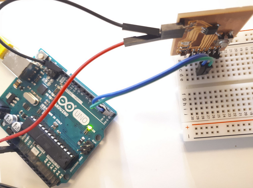
A video showing code execution, connection and setup.
Network Design 02
A 3-Node network was built:
- 2 identical boards ((See board from Electronic Design), Node 1 and Node 2.
- A PC, Node 0
The boards were serially connected (daisy-chained) PC acts as Master Node. The other two boards act as Slaves’ Nodes – each has its address All Nodes were connected in series, using an FTDI USB cable (connected to the network via serial connection).
A bread board was used as “Hub” to connect the Slave Nodes to the Master Node. Network interactions and control is accessed via a serial monitor.
Figure shows network topology
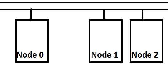
Figure shows Nodes connected.
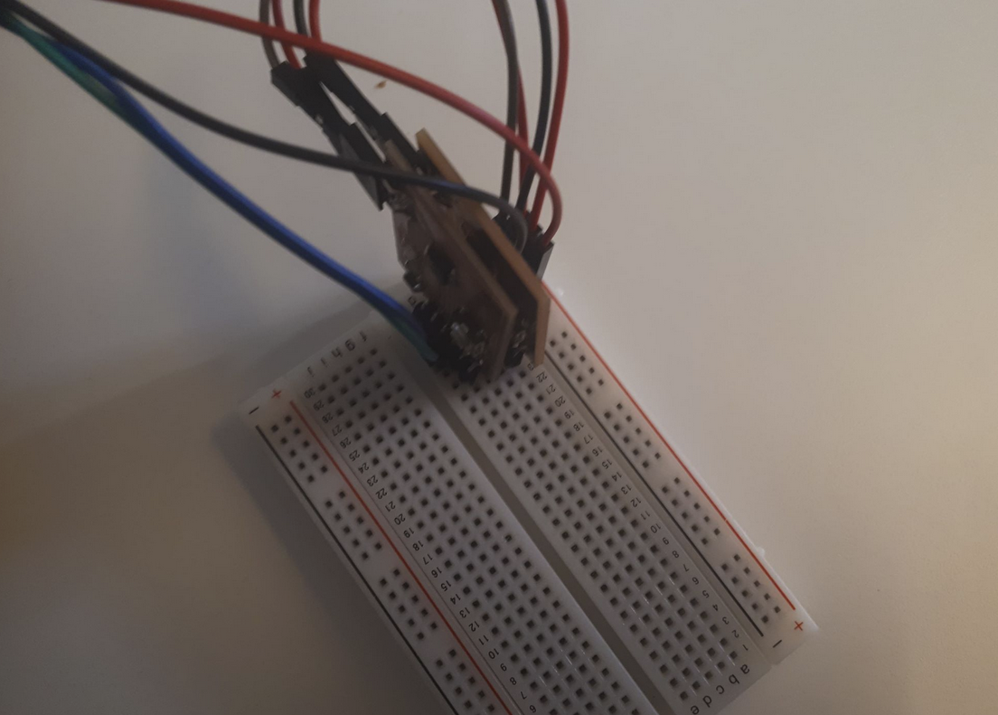
The Slaves’ Nodes each contain an ATTiny412 micro/controllers, an LED that is connected to pin PB2. LEDs are used as an output.
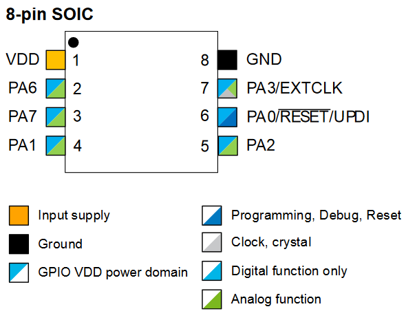
Features of the ATtiny212/412 micro-controllers are shown below:
Code for both Slave Nodes was the same except for Device ID. Data Byte 0 contains the Device ID of the Slave Node.
When data is received by the Slave Node, the Node checks if it is addressed to it (by checking the ID). If the Device ID matches, a command is executed ordering the LED to blink.
Note
This is a Master/Slave architecture. Only Master Node issues the command.
Code 02
#include <SoftwareSerial.h>
#define DEVICE_ID  '1'
#define ledPin x?

const int rx=0;
const int tx=1;
char serialData;

SoftwareSerial mySerial(rx,tx);

void setup() {
  pinMode(ledPin, OUTPUT);
  mySerial.begin(9600);
  digitalWrite(ledPin, LOW);
}

void loop() {
  if(mySerial.available()>0){
    serialData = mySerial.read();
    if (serialData == DEVICE_ID){
      while (!(mySerial.available()>0)){} //waiting for the command data
      serialData = mySerial.read();
      for (int i=0; i<(serialData-48); i++){  // ASCII to Decimal
        delay(300);
        digitalWrite(ledPin, HIGH);
        delay(300);
        digitalWrite(ledPin, LOW);
      }
    }
    mySerial.println(1);
  }
  delay(250);
}
Code Execution is shown Below. Slave Nodes’ when addressed Slave Node 2
Note
This has been completed in group work!
Group Work
https://fabacademy.org/2020/labs/oulu/students/xinhui-hu/Week14_Interface_and_Application.html#group