5. Electronics Production
-
Individual Assignment
- Make an in-circuit programmer by milling and stuffing the PCB,
- Test it
- Optionally try other PCB processes
-
Group Assignment:
- Characterize the design rules for your PCB production process
Individual Assignment
We decided to go with fablaboulu board. It is a updi programmer that utilizes Arduino IDE to program AVR microcontroller.
Milling
-
For milling, we use a Roland SRM-20 with a 0.2-0.5 mm V-milling bit.
-
A calibration file was used for calibrating the milling depth to reach the correct milling width with a V-shape milling bit.
-
When calculating the toolpaths with mods:
- 0.23 mm for traces and calibration.
- 1 mm for the outline.
Making an .rml files
To Convert from a .png files to .rml
-
Machine: Roland monofab SRM-20.
-
Go to mods.
-
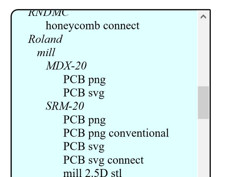
Right-Click: Programs / open server program / Roland / mill SRM-20 / PCB png.
- Import the .png file for tracing or cutout layouts for the PCB board.
Making an .rml file (Circuit tracing)
-
read png module
- select png file
- invert: machine mills the black and leaves the white.
- Check the dpi and size of the imported image.
Figure below shows importing a .png file, for tracing, to mods for the Roland monofab SRM-20.
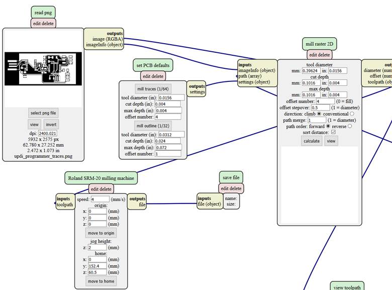
-
Roland SRM-20 milling machine module
- Set origin (x0, y0, z0) to zero.
-
PCB defaults module
-
mill traces 1/64
- 1/64 inch (0.4) diameter (especially suitable for FR1 boards) or PCB Isolation milling V tool with diameter 0.2-0.5 mm especially suitable for FR4 boards.
-
-
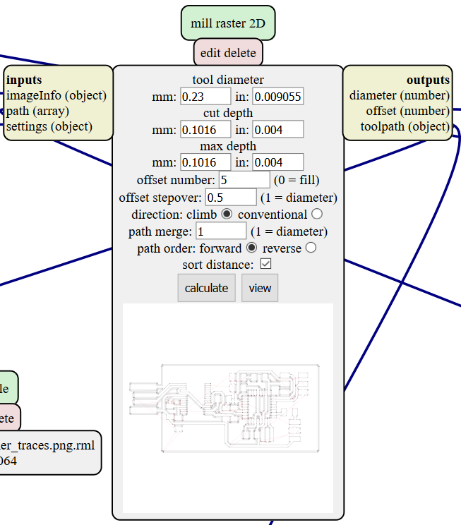
mill raster 2D module
- set tool diameter to 0.23mm.
- Set cut depth to. 0.1mm.
- set offset number to 5.
- set offset stepover to 0.5.
- Press the calculate button
- Finally, save the .rml file!
Figure below shows importing a .png file, for tracing, to mods for the Roland monofab SRM-20.
Making an .rml file (Calibration file)
-
read png module
- select png file
- invert: machine mills the black and leaves the white.
- Check the dpi and size of the imported image.
-
set PCB defaults module
- mill traces 1/64
-
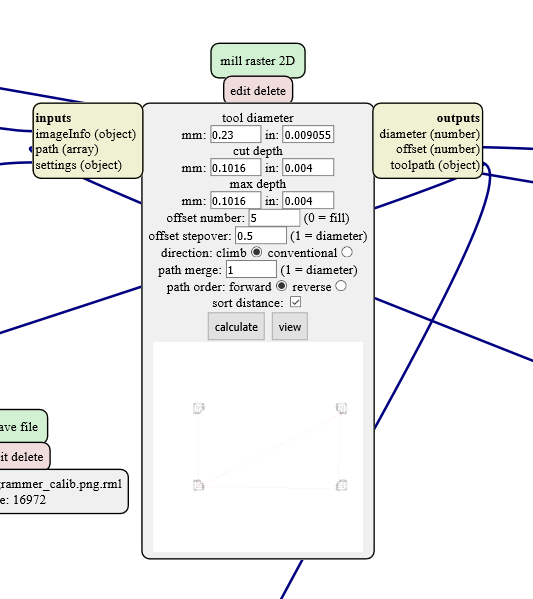
mill raster 2D module
- set tool diameter to 0.23mm.
- Set cut depth to. 0.1mm.
- set offset number to 5.
- set offset stepover to 0.5.
- Press the calculate button
- Finally, save the .rml file!
Figure below shows importing a .png file, for calibration, to mods for the Roland monofab SRM-20.
Making an .rml file (layout)
-
read png module
- select png file
- invert: machine mills the black and leaves the white.
- Check the dpi and size of the imported image.
-
set PCB defaults module
-
milling bit for cutout:
- 1/32 inch (0.79 mm) diameter or similar both with up to 1.00 mm diameter.
-
-
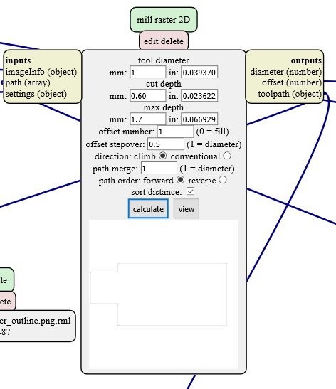
mill raster 2D module
-
set tool diameter to 1mm.
-
Set cut depth to 0.6mm.
- The cut depth was set to 0.6mm, which means the milling bit accomplishes the cutting process within three rounds, cutting 0.6mm deep in each round.
-
set offset number to 1.
- set offset stepover to 0.5.
- Press the calculate button
- Finally, save the .rml file!
-
Figure below shows importing a .png file, for layout cutout, to mods for the Roland monofab SRM-20.
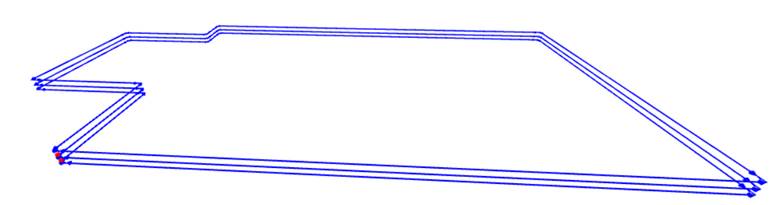
Note
When press the view button, the calculated output can be seen from different angles by dragging the mouse while holding the right click button. This is shown in figure below.
Preparing the material and setting up the milling machine
-
We used FR-1 material
“FR-1 is a hard, flat material that consists of a thin layer of copper over a non-conductive phenolic resin.”
-
We needed to make the material board smaller, it helps in having a level surface; without raised areas or indentations.
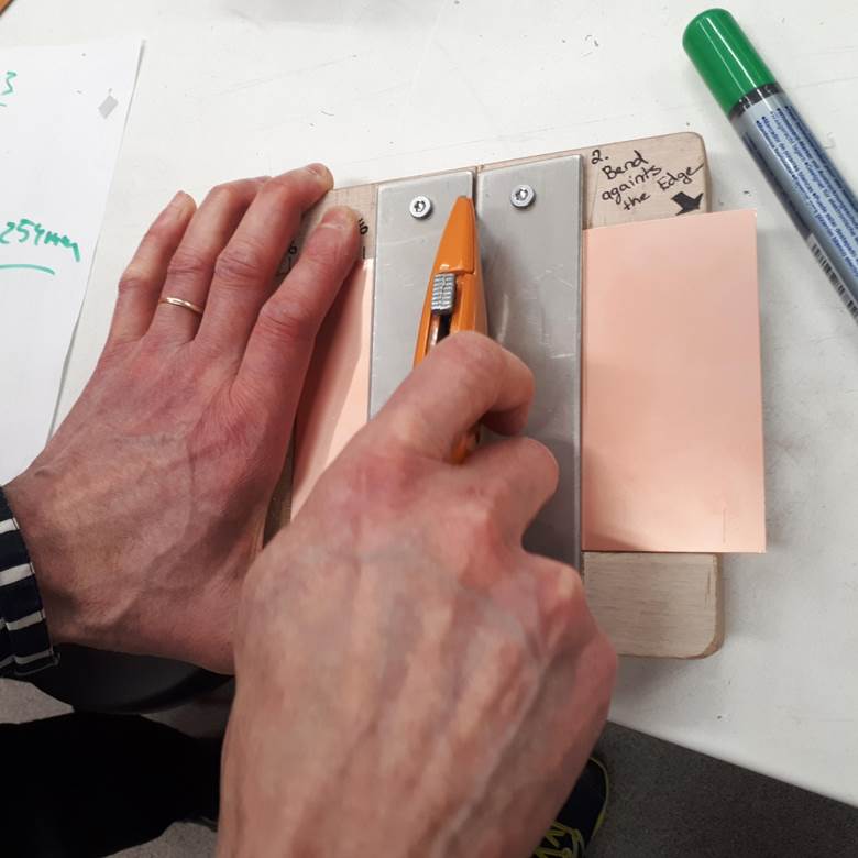
- We used double sided tape for attaching the material board onto support on the milling machine bottom plate.
-
Changing the milling bit, using a HEX key.
-
Ready for milling!
Using the milling machine
This is done using the Vpanel for SRM-20: the milling machine user interface software. See figure below.
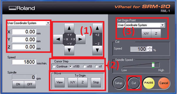
- Use X/Y buttons (1) to move the milling bit.
- Cursor Step (2) can be used for controlling the stepping.
- Set X/Y origin (3).
- Use Z buttons (1) to move the milling bit.
- Cursor Step (2) can be used for controlling the stepping.
- Set Z origin (3).
Note
Use the Hex key to loosen the mill bit and let it touch the surface. Tighten when done and Set Z origin (3).
- When ready, press Cut, Delete the old files, Add the desired file, and click on Output. This is shown in figure below.
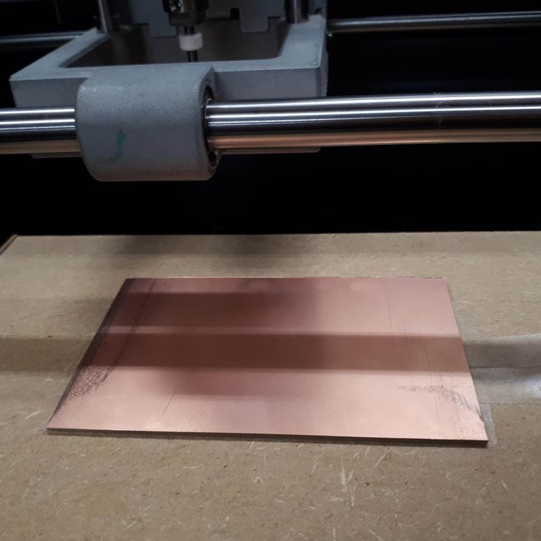
Figure below shows milling in action.
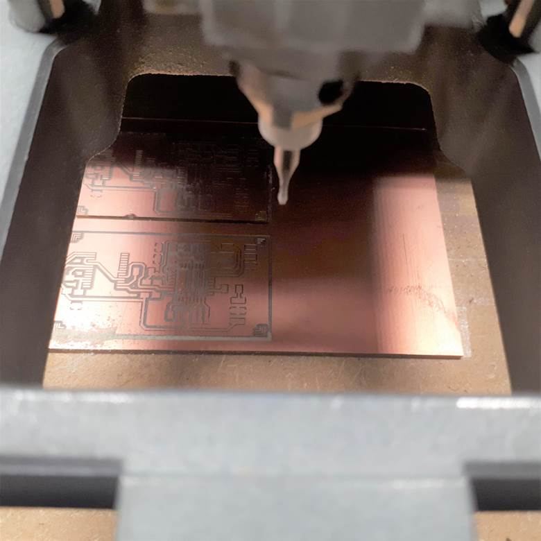
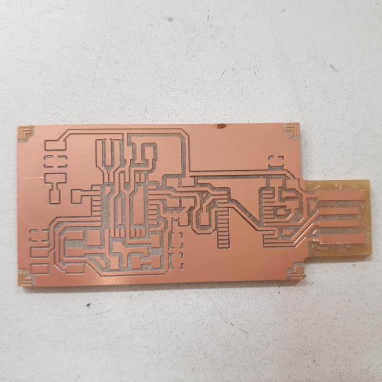
Figure below shows the final product, ready for soldering.
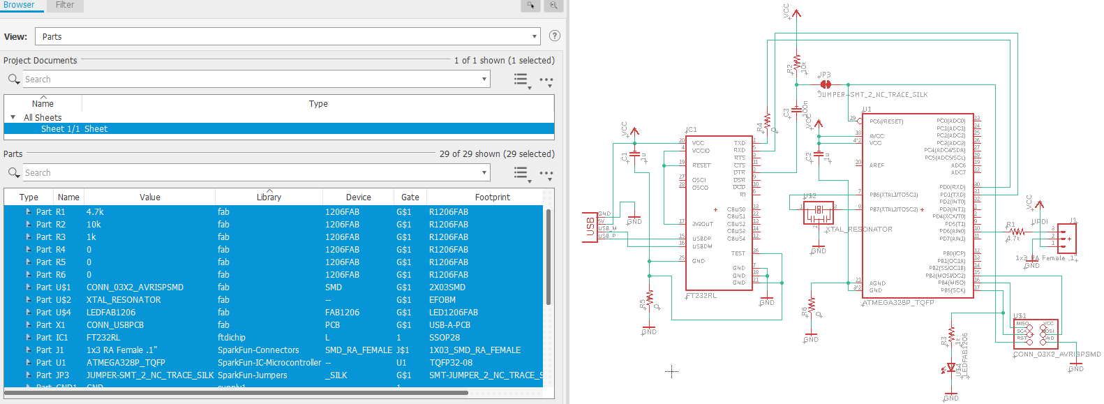
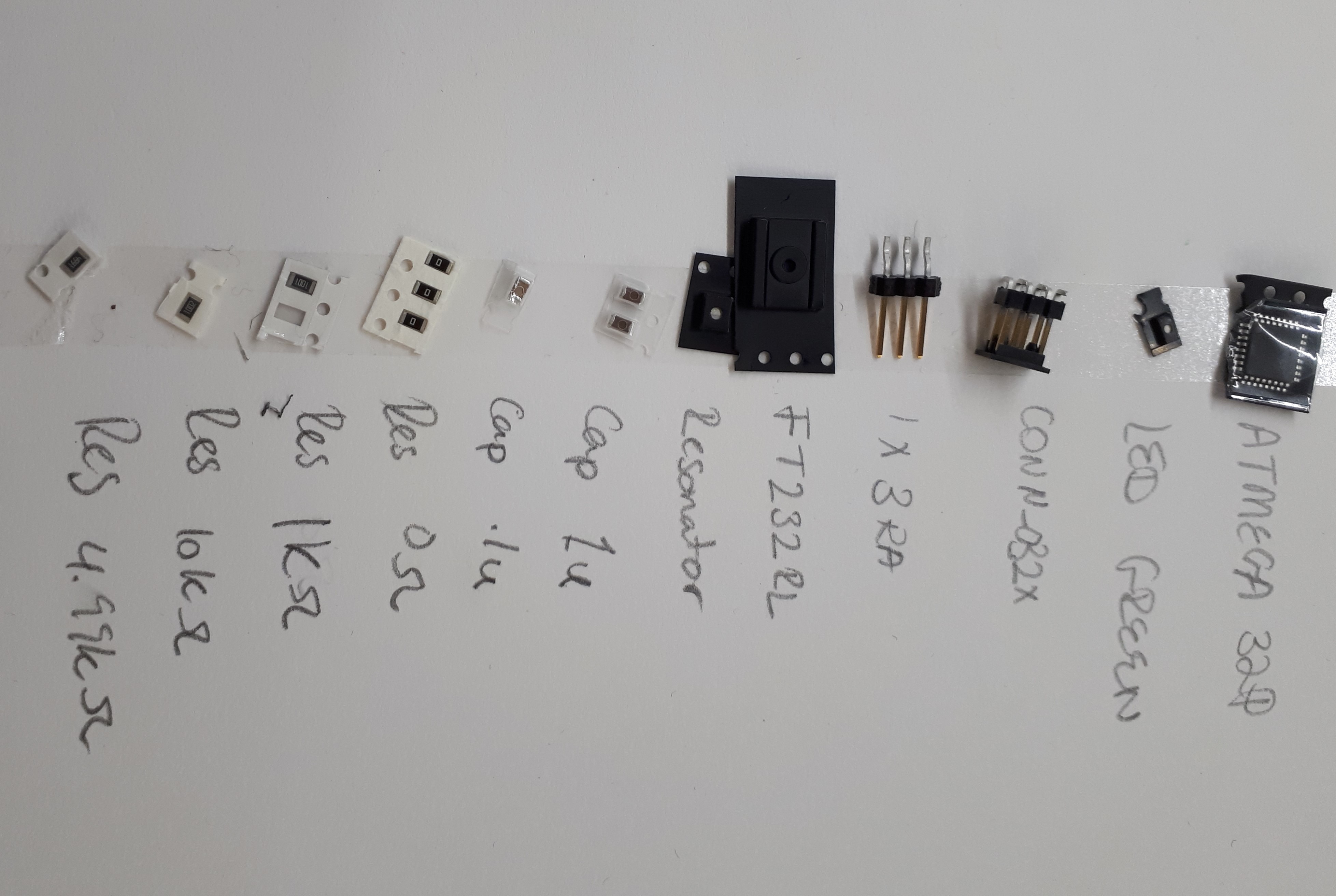
Soldering
Components
A list components can be found by viewing the board’s schematics in EAGLE PCB design software.
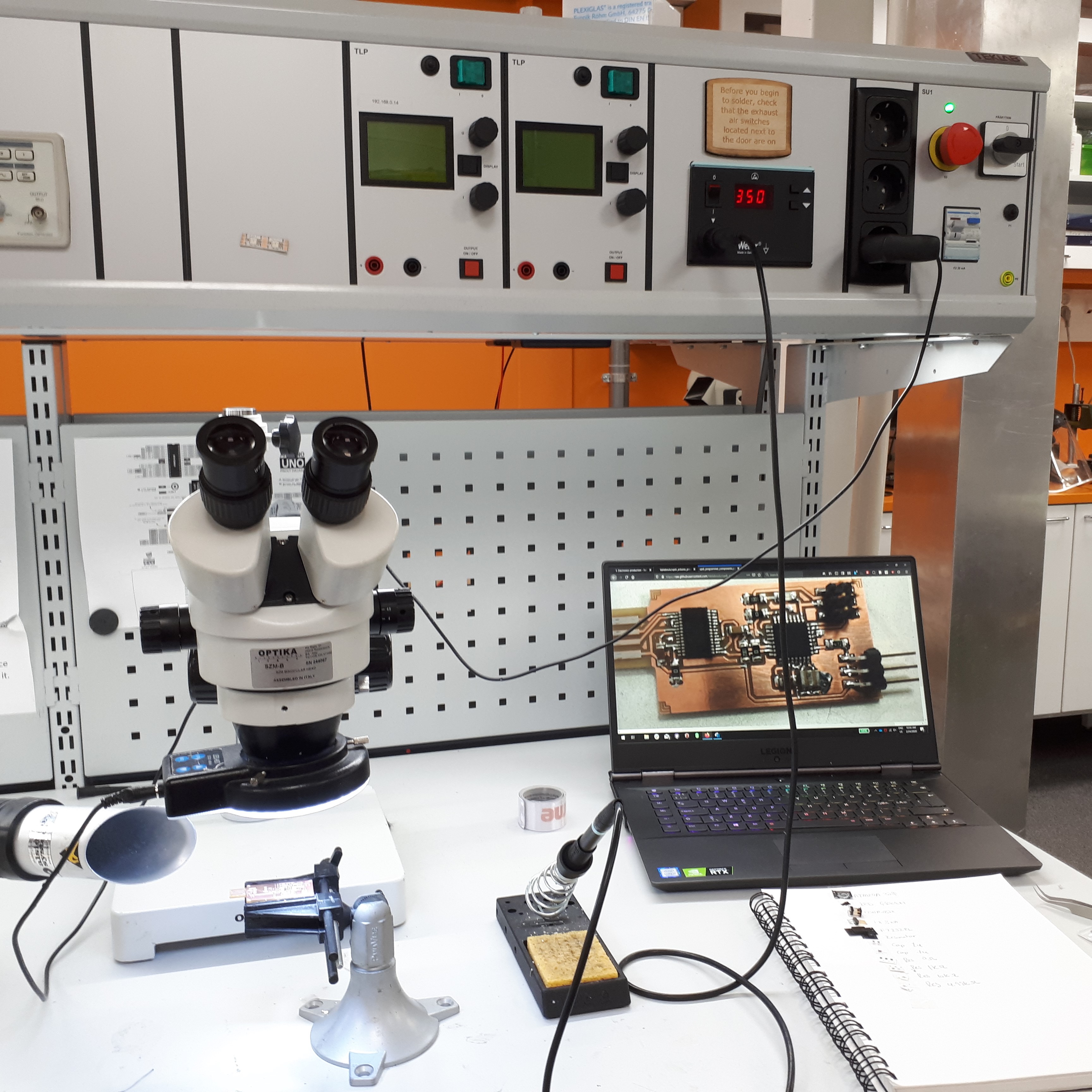
Set up
Programing
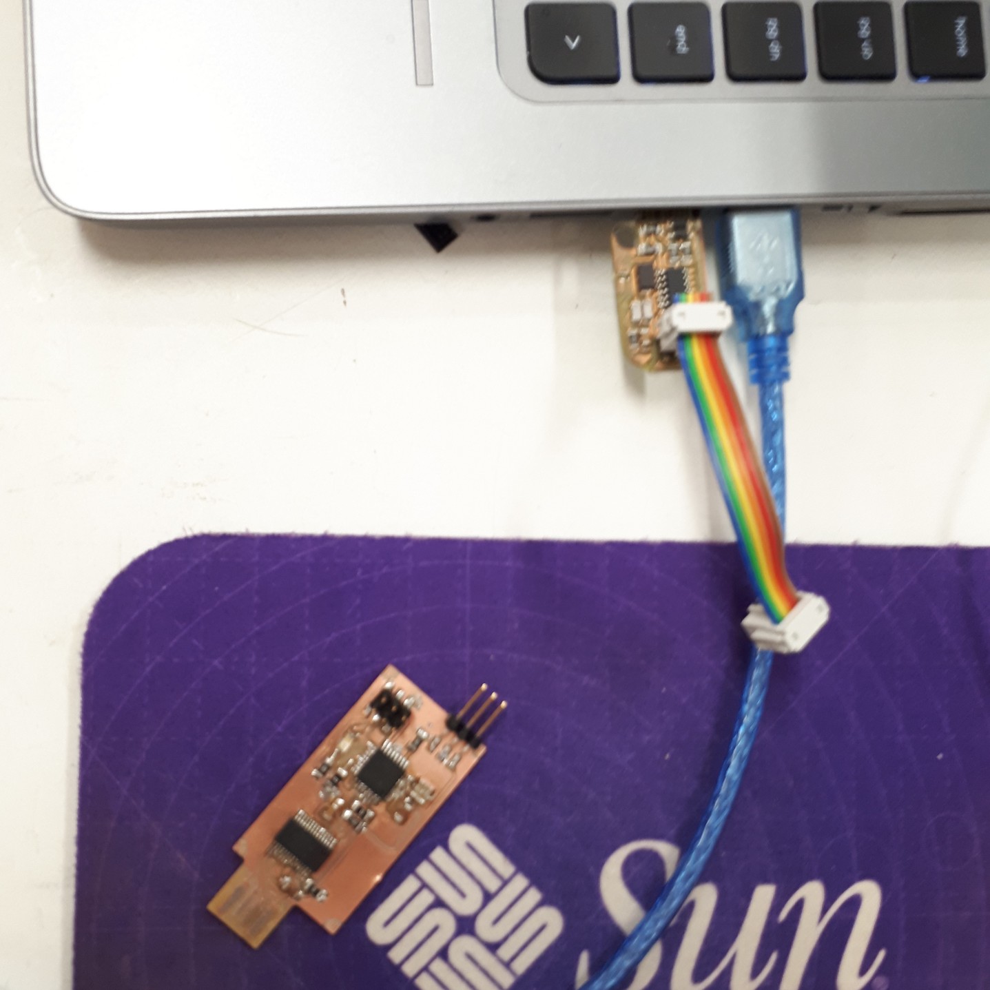
Burning the bootloader
This was done by connecting our board to another board using the ISP connectors, prepared by the instructor Antti Mäntyniemi. Setup and additional board shown in image below.
Under Tool on Arduino IDE, make sure that:
- Board: Arduino Nano
- Processor: ATmega328P (Old Bootleader)
- Port
- Programmer: USPTinyISP
After loading the bootloader, the board can be programmed as an Arduino Nano/Uno. Arduino Blink Test after burning the bootloader successfully.
Turn nano into a UPDI programmer
A tutorial showing how to set up an Arduino board as the UPDI Programmer and the process of setting up the megaTinyCore on your Arduino IDE can be found here
In short, to configure the board, more libraries are needed.
First, add the library
File > Preference > Additional Board Manager URLs
http://drazzy.com/package_drazzy.com_index.json
Then add the board:
tools > Boards > Boards Manager
Then install the megaTinyCore and megaAVR boards packages.
-
Cut circuit path between the FTDI and the ATTiny chips, so that the board does not reset to an arduino nano. This will turn it into a programmer.
-
You will notice that the blinking has stopped.
jtag2updi
UPDI sketch is needed to be uploaded to the board. Sketch can be found here. More information can also be found here.
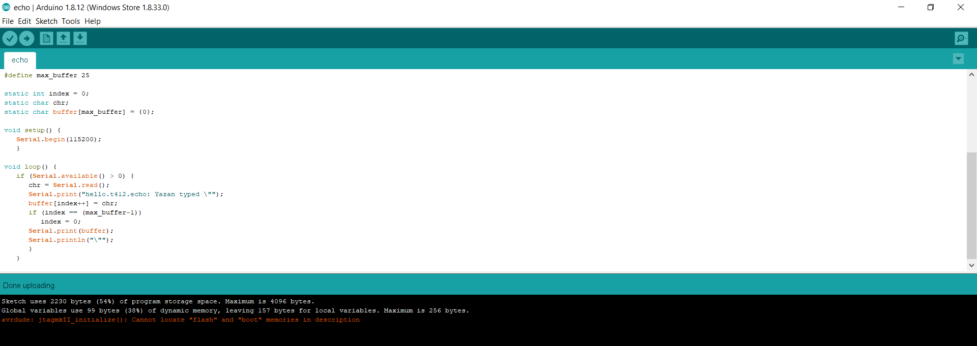
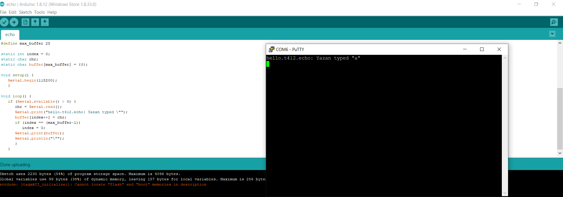
Application Board test: t412/hello.t412.echo.ino
Code can be found on FabAcedemy Website under embedded programming:
http://academy.cba.mit.edu/classes/embedded_programming/t412/hello.t412.echo.ino
Programming the application baord using the programmer board
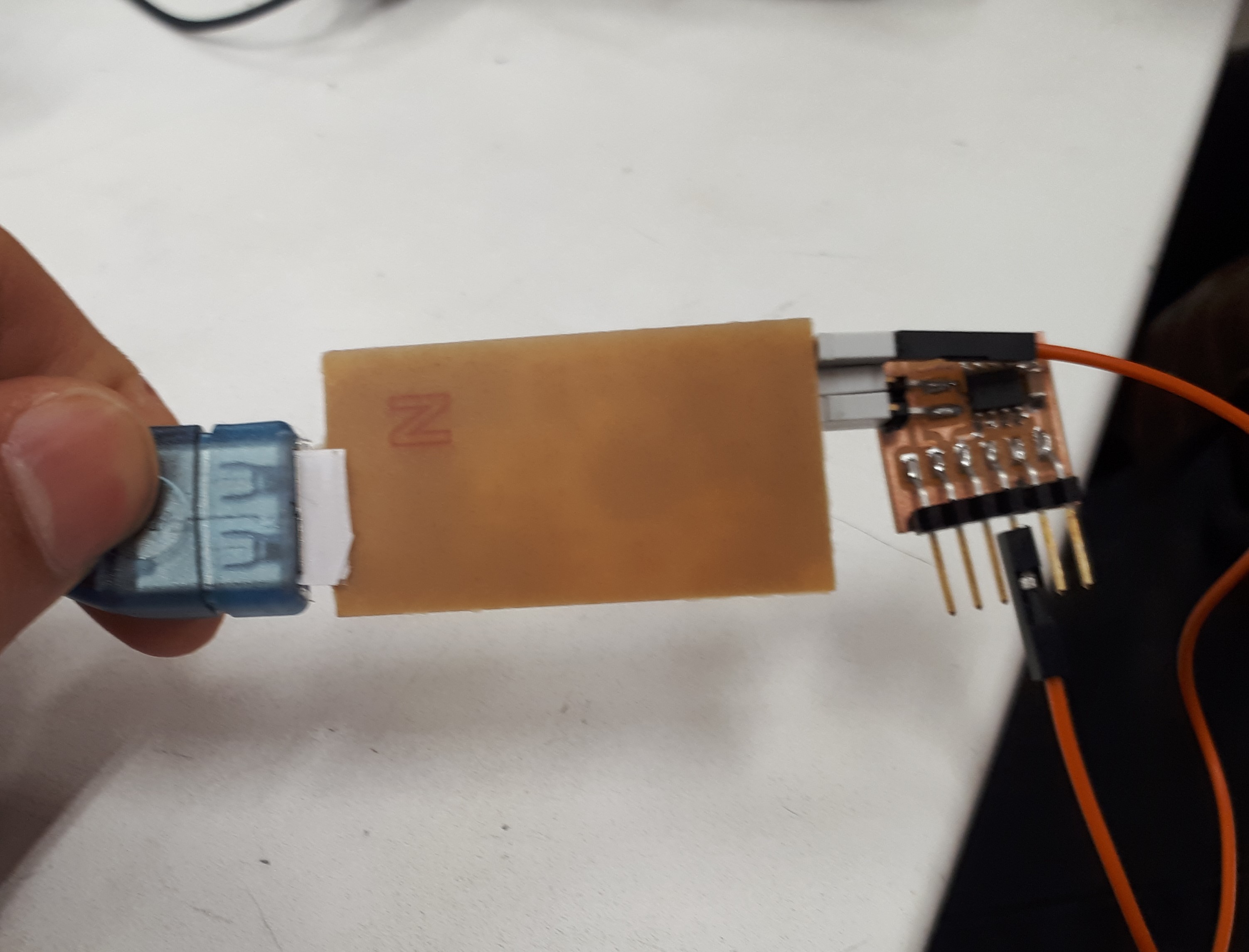
Uplopad the code
Under Tool on Arduino IDE, make sure that:
- Board: ATtiny412/402/212/202
- Programmer: jtag2updi(megaTinyCore)
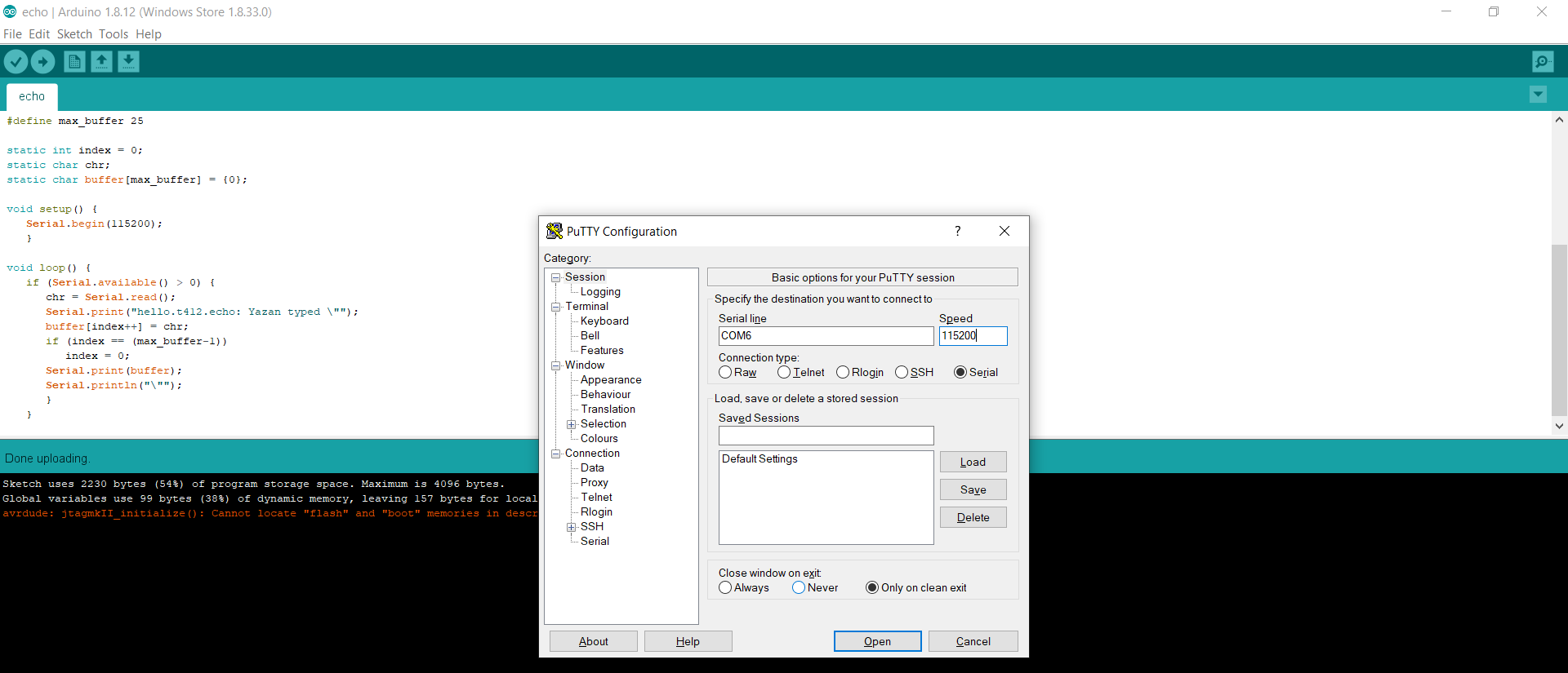
Cable
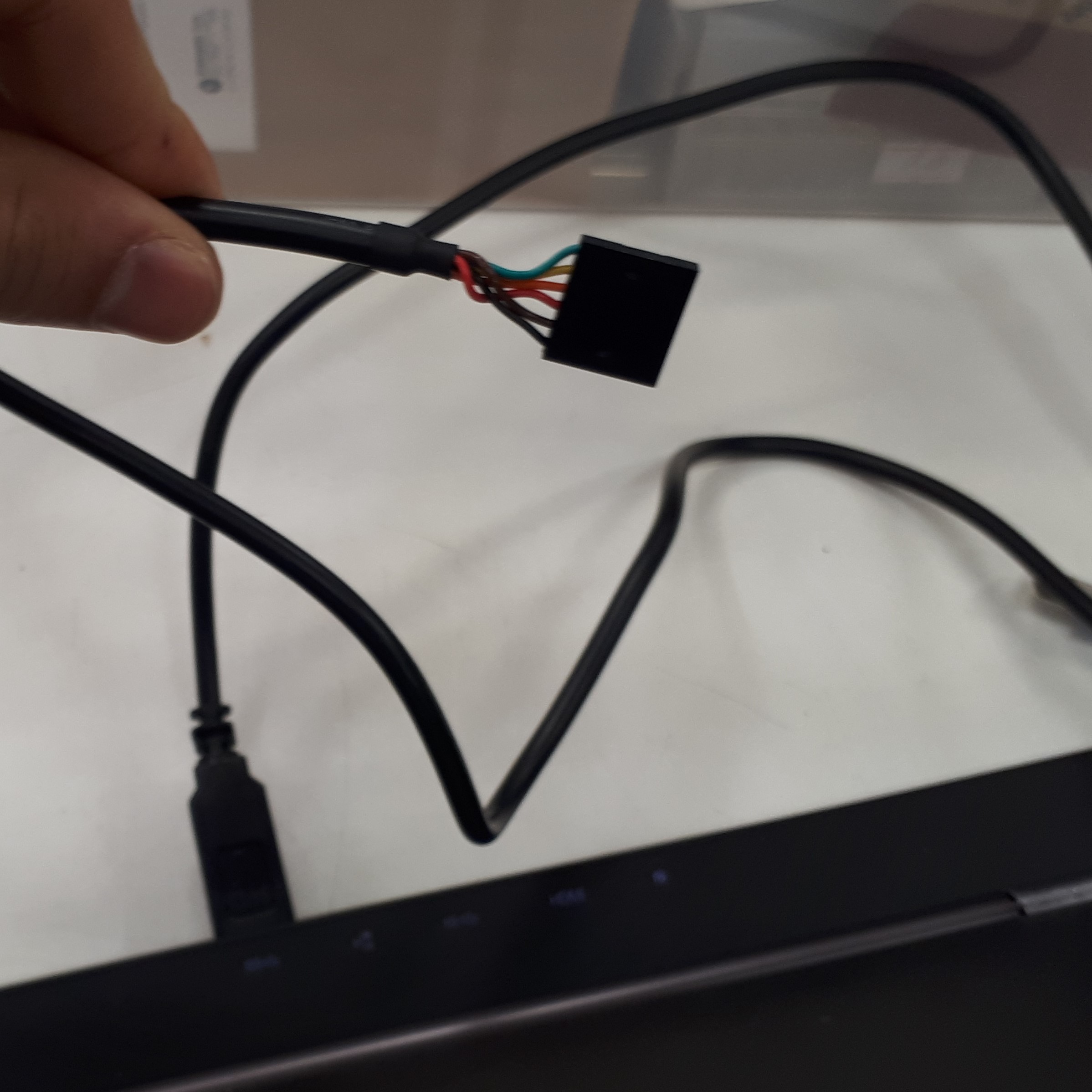
Cable being used for serial communication

PuTTy can be used for serial communication.
Group Assignment
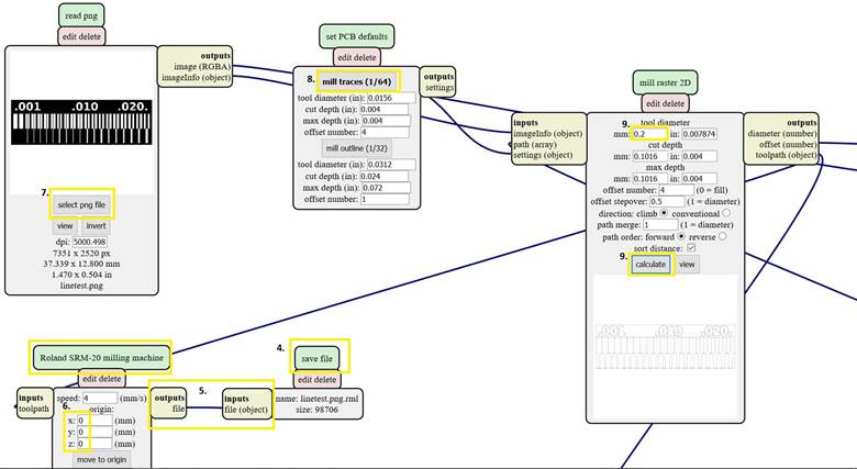
Mods operation
We generated .rml files using mods. The process was following:
- Save traces and interior .png files
- On mods:
Right click > programs > open server program > Roland/mill/SRM-20//PCB png
- Delete WebSocket device
Right click (next to Roland SRM-20 milling machine) > modules > open server module > file/save
- Combine Roland SRM-20 milling machine’s outputs file with save file’s inputs file by clicking outputs file and inputs file
- Change Roland SRM-20 milling machine’s x, y and z values to zero
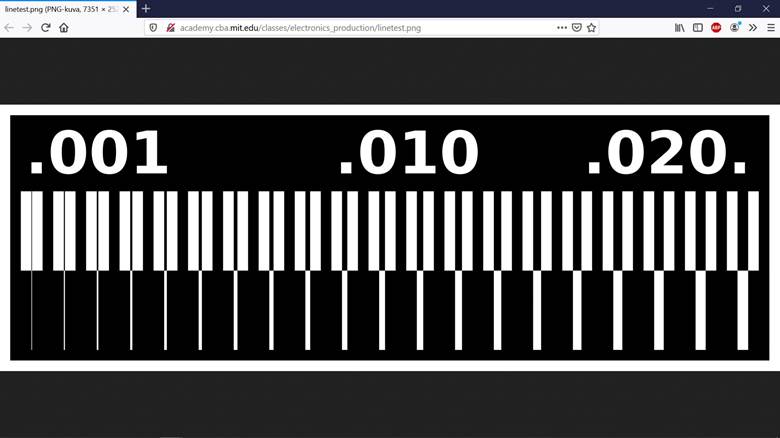
For Traces (linetest)
read png > select png file > open linetest.png
- set PCB defaults >> select mill traces
- mill raster 2D >> change tool diameter to 0.2mm >> calculate
- Save the .rml file
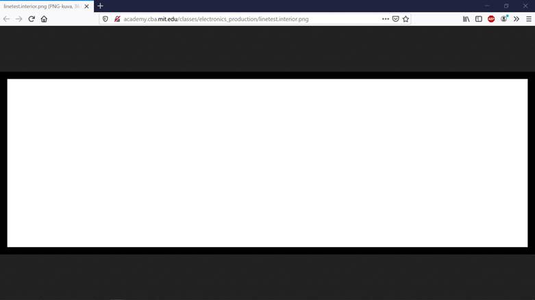
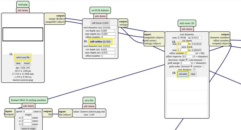
For Linetest interior
read png > select png file > open linetest.interior.png
- set PCB defaults > select mill outline
mill raster 2D > change tool cut depth to 0.6mm and max depth to 1.7 mm > calculate
- Save the .rml file
Milling Machine Operation: VPanel
We used a Roland SRM-20 milling machine to engrave the test patterns on the PCB board via VPanel software.
-
Navigation:
-
Adjust X/Y origin: The X/Y origin determines the start point on the flat PCB board. The X/Y direction buttons can be used to adjust the X and Y coordination of the milling bit. After reaching the ideal location, click Set Origin Point >> X/Y to set the current coordination as X/Y origin.
-
Adjust Z origin Z coordination determines the depth of the milling bit.
-
-
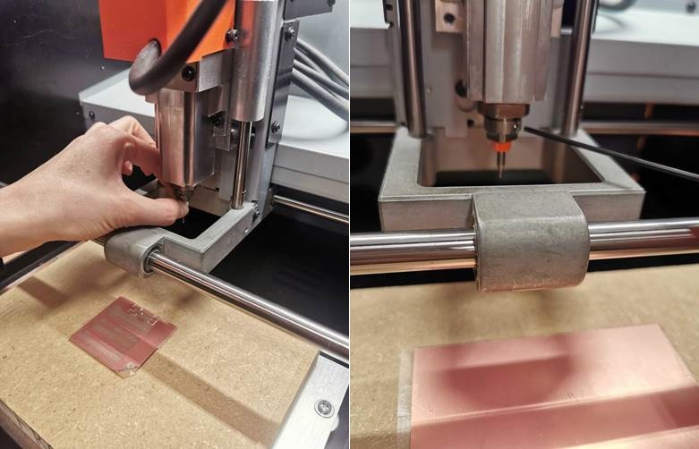
Use the Z direction button to lower the milling bit until it is close to the PCB board without touching it. Select a small cursor step when the milling bit comes close to the board.
-
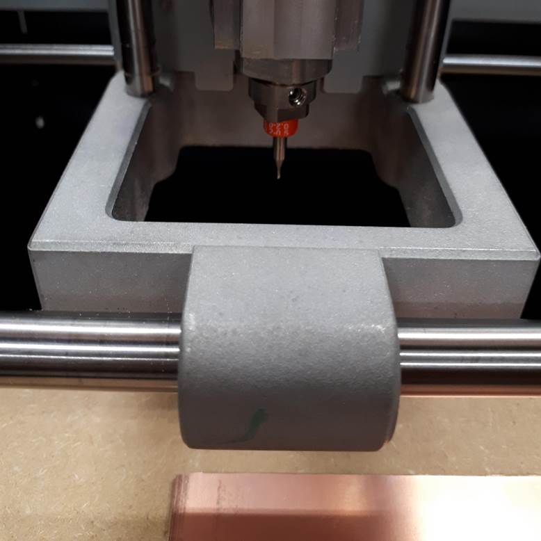
Hold the milling bit with one hand and use the hex key tool to gently release it with the other hand. Carefully let the tip of the milling bit touch the surface of the board and fasten it again.
-
Click Set Origin Point >> Z to set the current height as the Z origin.
-
Calibration For V-shape milling bit, it is necessary to calibrate how deep it cuts into the board. Rise Z for 0.30 mm and set the location as the new Origin Point of Z and test the cut depth with the rml files saved from mods.
-
Start the cutting task by Cut >> Add >> Select corresponding file >> Output. (*The cutting task will start immediately after clicking “Output”, please double check everything before that.).
-
Pause and Cancel the task if milling bit is not touching the PCB board, which is expected to happen in the early rounds of calibration.
-
In order to recalibrate, Click View >> To Origin >> Z to bring the milling bit back to its previous position. The order here is very important. Users must click “View” (which will bring the board forward) before clicking “To Origin Z”, otherwise the milling bit may be broken.
Note
Use the Z direction button to further decrease the height of the milling bit by a small amount and restart the test task. Repeat the routine until the milling bit cuts into the PCB board with appropriate depth. This depth will be set as the final origin of Z for this milling task.
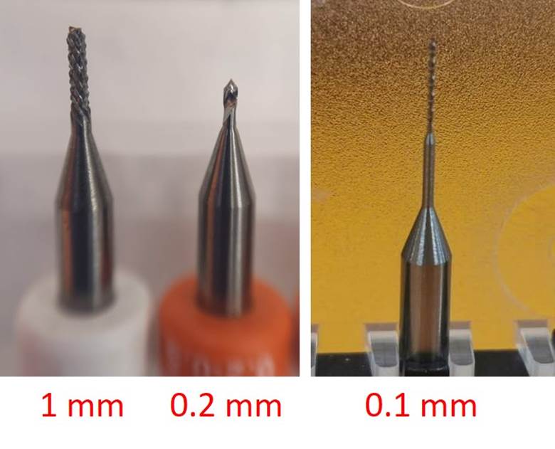
Milling bits
- Select milling bits There are many different sizes of the milling bits, for the inside milling, usually using the 0.2mm size as the figure. Also, we were cutting the outline using the 1.0mm size.
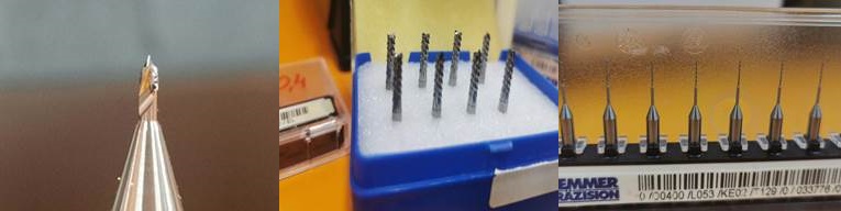
- Connect Milling bits To connect the cutter, hold Milling bits between our fingers and insert it in the place. Then use a hex wrench to tighten it.
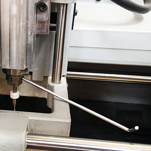
- Loosen the Milling bits When we had set up the XYZ, we need to loosen the Milling bits as shown on a figure.
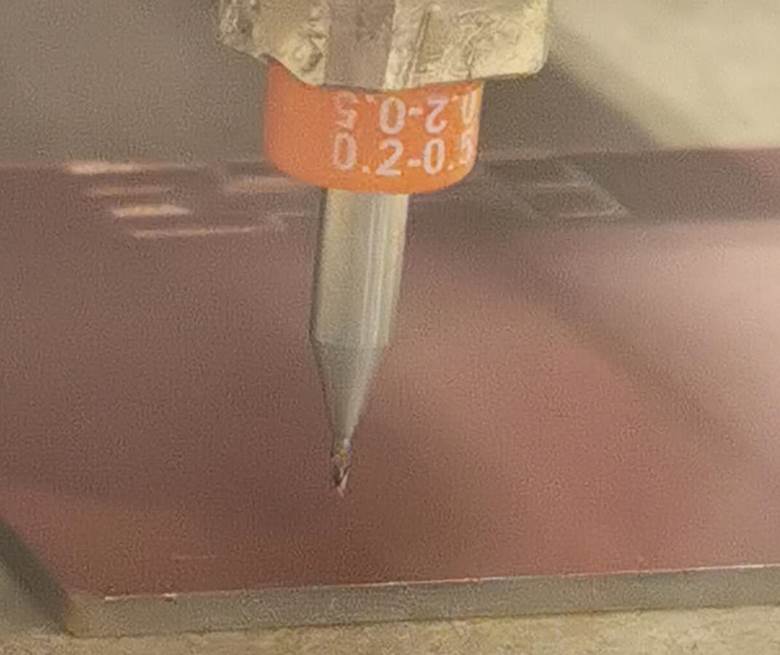
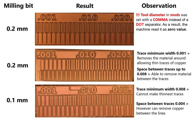
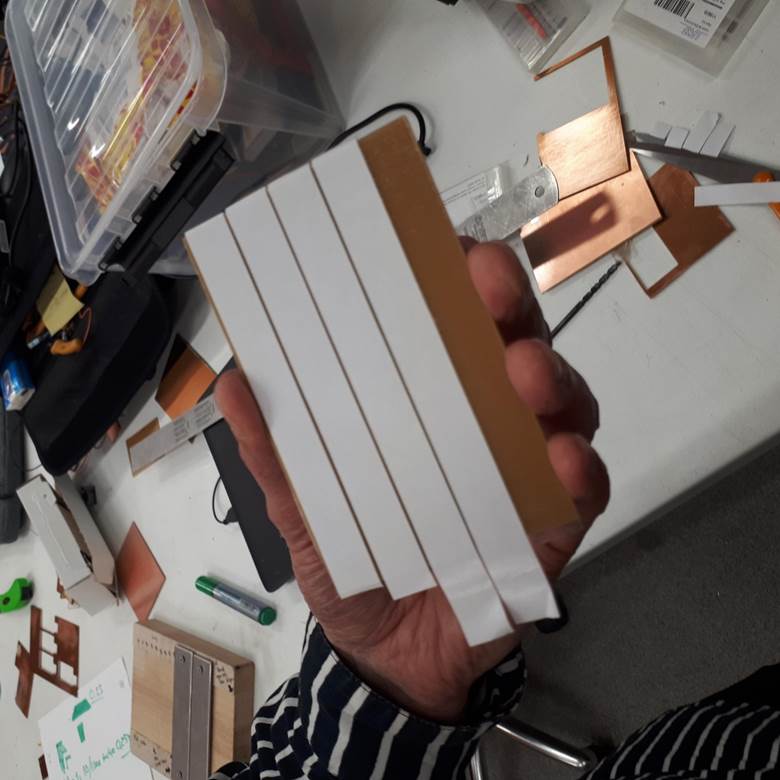
We tested three types of tool diameter (0, 0.1,0.2) and milling it as in the next figure.
Results